Note: Descriptions are shown in the official language in which they were submitted.
21 ~2756
CHIPPER KNIFE BABBITT REMOVAL TOOL
FIELD OF THE INVENTION
The present invention relates to a tool for use in the reconditioning
of chipper knives such as those used in chipping softwood for subsequent
processing.
BACKGROUND
A chipper knife used for chipping softwood is fixed to its carrier
using babbitt metal that is molten when the knife is installed and solidifies as a
block on the back of the knife to hold the knife in place. The knife must
occasionally be removed from the carrier for sharpening. To complete this
operation, it is necessary to remove the block of babbitt metal from the back ofthe knife. This is conventionally done manually, using a cold chisel and a
hammer, which is time consuming and labour intensive work.
The present invention is concerned with the provision of a tool
that will serve to remove the babbitt metal.
SUMMARY
According to the present invention there is provided a tool for
removing a block of babbitt metal from a chipper knife, said tool comprising:
a channel comprising two spaced apart rails and having an open
front side;
knife support means extending at least partially across the open
front side of the channel, between the rails for supporting the chipper knife
with the block of babbitt material in the channel and for limiting movement of
the knife along the channel;
a blade slideable along the channel for engaging the block of
babbitt metal therein, the blade being spaced rearwardly from the knife support
21 ~2756
means; and
a cylinder secured to the channel and to the blade, the cylinder
being actuable to drive the blade along the channel to impact on the block of
babbitt metal.
Preferably, the tool includes a receptacle at one end into which the
free babbitt metal will fall when removed.
In one exemplary embodiment of the invention, the tool comprises:
a vertical base;
two vertical rails mounted on the base and projecting to a front
side of the base, the rails being spaced apart to define a channel therebetween;knife support means secured to the rails and extending into the
channel at a position spaced from the base for limiting the travel of the knife
downwardly along the channel;
a blade slideable along the channel between the base and the knife
support means, and spaced from the knife support means for engagement with
the top of the block babbitt metal, the blade having a thickness less than the
thickness of the block of babbitt metal; and
a cylinder mounted on the base above the channel, the cylinder
being connected to the base and to the blade and being actuable to drive the
blade along the channel into engagement with the block of babbitt metal.
BRIEF DESCRIPTION OF THE DRAWINGS
In the accompanying drawings, which illustrate a chipper knife and
an exemplary embodiment of the present invention:
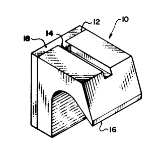
Figure 1 is an isometric view of a chipper knife;
Figure 2 is a front view of a tool according to the present
21 92756
invention;
Figure 3 is a side view of the tool of Figure 2;
Figure 4 is a detail of the tool, partially in cross-section, showing a
chipper knife in place; and
Figure 5 is a transverse cross-section of the tool along line 5-5 of
Figure 2.
DETAILED DESCRIPTION
Referring to the accompanying drawings, Figure 1 illustrates a
chipper knife 10 with a back face 12. A keyway 14 extends along the center
of the back face. At the front of the knife is a blade 16 that requires periodicsharpening. On the back of the knife is a block of babbitt metal 18 that covers
the back of the knife and fills the keyway 14. When a blade is to be
sharpened, the block of babbitt metal 18 is conventionally removed using a
cold chisel and a hammer.
Referring to Figures 2 through 5, there is illustrated a tool 20 for
removing the babbitt metal block 18 from the knife 10. The tool includes a
base 22 in the form of a channel with a web 24 and two flanges 26 projecting
to the rear of the tool. In use, the channel is arranged with the web and
flanges oriented vertically.
Mounted on the front of the base web 24 are two rails 28. These
extend part way along the web, at its opposite edges. The rails define, with
the web 24, a channel 30. Along the front face of the web, each rail has a
groove 31 in its inner face, confronting the groove in the other rail.
Adjacent at their bottom ends, the two rails carry knife supports
32 which are located in front of the channel 30 and project towards one
21 92756
another across the front of the channel 30.
A rectangular blade 34 slides along the channel 30, in the two
grooves 31. Near its upper end, on its front face, the blade carries a lug 36.
This is pinned to the piston rod 38 of a pneumatic cylinder 40 by a pin 41. The
cylinder is fastened to the base 22 by a clamp plate 42 and two bolts 43. The
end of the cylinder has two lugs 44 that are pinned to a lug 46 on the base by
a cross-pin 48.
The cylinder and rod end ports 50 and 52 respectively of the
cylinder 44 are connected to a control valve 56 by two air lines 58 and 60. A
pedal operated actuator 62 is connected to the control valve by an air line 64
for controlling the delivery of air to the cylinder.
At the bottom end of the base 22 is a container 66 with an open
top end 68 and a cover 70 that slopes downwardly to the front, over the open
top. The cover is connected to the container by two hinges 72 at opposite
sides of the base. Between the two hinges the cover 70 has a rectangular slot
74 positioned directly below the channel 30.
In use, a knife is supported in the channel by the knife supports
32, as shown most particularly in Figure 3. The babbitt metal block 18 rests
against the front face of the base web 24 and the knife supports engage in the
cavity under the blade 16. When the cylinder is actuated, it drives the blade
34 downwardly along the channel to impact on the babbitt metal block and to
drive it off the knife. The separated babbitt metal falls from the channel,
through the slot 74 into the container 66 at the bottom end of the tool.
Use of this tool has been found to provide a considerable
reduction in the amount of time and labour involved in sharpening a set of
21 92756
chipper knives.
While one embodiment of the present invention has been
described of the foregoing, it is to be understood that other embodiments are
possible within the scope of the invention and are intended to be included
herein. The invention is to be considered limited solely by the accompanying
claims.