Language selection

Search

Patent 2192830 Summary

Third-party information liability

Some of the information on this Web page has been provided by external sources. The Government of Canada is not responsible for the accuracy, reliability or currency of the information supplied by external sources. Users wishing to rely upon this information should consult directly with the source of the information. Content provided by external sources is not subject to official languages, privacy and accessibility requirements.

Claims and Abstract availability

Any discrepancies in the text and image of the Claims and Abstract are due to differing posting times. Text of the Claims and Abstract are posted:

  • At the time the application is open to public inspection;
  • At the time of issue of the patent (grant).
(12) Patent: (11) CA 2192830
(54) English Title: DISPLAY ASSEMBLY FOR POSTERS AND LIKE PRINTED MATERIAL
(54) French Title: ENSEMBLE DE PRESENTATION POUR AFFICHES ET POUR PRODUITS IMPRIMES SIMILAIRES
Status: Expired
Bibliographic Data
(51) International Patent Classification (IPC):
  • G09F 1/12 (2006.01)
(72) Inventors :
  • PENISSON, GERARD (Canada)
(73) Owners :
  • PENISSON, GERARD (Canada)
(71) Applicants :
  • PENISSON, GERARD (Canada)
(74) Agent: GOUDREAU GAGE DUBUC
(74) Associate agent:
(45) Issued: 2006-03-14
(86) PCT Filing Date: 1995-04-21
(87) Open to Public Inspection: 1995-12-21
Examination requested: 1999-03-09
Availability of licence: N/A
(25) Language of filing: English

Patent Cooperation Treaty (PCT): Yes
(86) PCT Filing Number: PCT/CA1995/000234
(87) International Publication Number: WO1995/034877
(85) National Entry: 1996-12-12

(30) Application Priority Data:
Application No. Country/Territory Date
9411899.9 United Kingdom 1994-06-14

Abstracts

English Abstract


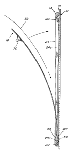
A display assembly (10) comprises a rectangular frame
(14) wherein each peripheral frame member (18, 20, 22, 24) is
formed of a flat inner portion and of a frontwardly projecting
portion. A rectangular flexible transparent sheet (16) is confined
within the rectangular frame (14) and strips of magnetic material
are provided on the flat inner portions of three frame members
(18, 22, 24) and on the back surface of three borders of the
transparent sheet. The bottom edge of the sheet is fixedly
secured to the bottom frame member (20) so that the sheet
may be flexed outwardly about the bottom edge and a display
sheet may be inserted rearwardly of the sheet and thereafter
retained in the assembly by the mutual engagement of the strips
of magnetic material.


French Abstract

Un ensemble d'affichage (10) comporte un cadre rectangulaire (14) dont chaque élément périphérique (18, 20, 22, 24) est constitué d'une partie interne plate et d'une partie saillant vers l'avant. Une feuille transparente (16) souple et rectangulaire est confinée dans le cadre rectangulaire (14), et des bandes de matériau magnétique sont prévues sur les parties internes plates de trois éléments (18, 22, 24) du cadre et au recto des trois bordures de la feuille transparente. Le bord inférieur de la feuille est monté fixe sur l'élément de cadre inférieur (20), de sorte que la feuille puisse être fléchie vers l'extérieur sur le bord inférieur, et une feuille à afficher peut être insérée à l'arrière de la feuille et retenue par l'ensemble par contact mutuel des bandes de matériau magnétique.

Claims

Note: Claims are shown in the official language in which they were submitted.


- 9 -

CLAIMS

The embodiments of the invention in which an exclusive
property or privilege is claimed are defined as follows:

1. A display assembly comprising:

a rectangular frame formed of a top member,
opposite side members and a bottom member, each of said
top and opposite side members having a face edge; a first
magnetic holding means being fixedly mounted along a
continuous length of the face edge of each one of said top
and opposite side members;

a rectangular flexible transparent sheet having
a top edge, opposite side edges and a bottom edge; said
bottom edge of the sheet being fixed to an inner surface
of said bottom frame member; a second magnetic holding
means being fixedly secured along a continuous perimeter
of a back surface of said sheet adjacent said top and
opposite side edges thereof of said sheet;

wherein, said flexible transparent sheet is in
one of a first and a second positions, said sheet being in
confinement within said frame by a mutual continuous
engagement between said first and second magnetic holding
means in said first position; said sheet being outwardly
flexed from said frame in said second position by action
of hand-gripping suction means removably adhered to an
outer face of said sheet allowing said sheet to be flexed
outwardly from said first position, thereby allowing a
display sheet to be inserted rearwardly of said sheet and
thereafter retained in said assembly when the sheet is
back in said first position.


- 10 -

2. The display assembly as defined in claim 1,
each member of said frame defining a front portion and a
recessed portion extending inwardly of said front portion;
said recessed portion displaying a generally flat inner
surface, said edges of the sheet extending inwardly of
said front portions of said frame members onto said inner
surfaces of said recessed portions, wherein said top and
opposite side edges of said sheet substantially abut inner
side walls of said front portions of said top and opposite
side members of said frame so as to borderly confine said
sheet within said frame in said first position.

3. The display assembly as defined in claim 2,
wherein said first magnetic holding means extend
lengthwise on said inner surface of said recessed portions
of said top and opposite side members of said frame, and
said second magnetic holding means extend lengthwise on
said back surface adjacent said top and opposite side
edges of said sheet.

4. The display assembly as defined in any one
of claims 1 to 3, wherein said magnetic holding means
consist of flexible strips of ferromagnetic material.

5. The display assembly as defined in any one
of claims 1 to 4, further comprising an opaque band
extending along said top, bottom and opposite side edges
of said transparent sheet thereby concealing said first
and second magnetic holding means.

6. The display assembly as defined in any one
of claims 1 to 5, comprising a strip of double-sided
adhesive material along an inner surface of said bottom


- 11 -

frame member fixedly securing a back surface of the bottom
edge of the transparent sheet to the bottom member of the
frame.

7. The display assembly as defined in claim 6,
wherein said strip of double-sided adhesive material has a
thickness corresponding to a thickness of said first and
second magnetic holding means when mutually engaged to one
another.


Description

Note: Descriptions are shown in the official language in which they were submitted.


WO 95/34877 219 2 8 3 0 -
PCT/CA95I00234
TITIaE OF THE INVENTION
Display assembly for posters and like printed
material.
FIEhD OF THE INVENTION
The present invention pertains to a display
assembly to receive posters and like printed material
where it is desirable to change the display at more or
less frequent intervals.
BACRGROOND OF THE INVENTION
Various assemblies have been used in the past
for the display of printed material such as posters,
advertisements, photographs, drawings and the like. Some
of these assemblies are constructed to be particularly
useful in situations where it is wished to change the
display at certain time intervals. They are constructed
in a manner that they may be disassembled and reassembled
to facilitate the interchange of printed material.
On the other hand, posters or like printed
material are frequently defaced, obliterated or removed
2o by vandals so that many of these display assemblies do
not provide adequate protection against vandalism or
weather elements. In some cases, they do not allow for
a convenient interchanging of the articles that they are
displaying without damaging the article.


WO 95!34877 2 l 9 2 8 3 0 PCT~CA95100234
- 2 -
Canadian patent No. 1,246,868 issued December
20, 1988 to Kane et al. describes a weather-sealed
tamper-proof display assembly designed to accept two-
dimensional articles which comprises two major components
held to each other by magnetic holding means. However,
this type of display assembly requires a specially
configured tool in the form of a blade or spatula in
order to effect a separation of the two components and a
change of display material.
OBJECTS A_ND STATEMENT OF THE INVENTIOAi
It is an object of the present invention to
provide a display assembly which overcomes the above
described problems of presently used devices.
It is also an object of the present invention
to provide a display assembly which does not make it easy
for unauthorized persons to reach the display material.
It is a further object of the present invention
to provide a display assembly wherein weather-proof
features are improved.
The present invention therefore relates to a
display assembly which comprises:
a rectangular frame formed of top, bottom and
0
opposite side members; each member defining a front


W O 95134877 PCT/CA95/00234
- 3 -
portion and a recessed portion extending inwardly of the
~ front portion; the inner portion displaying a generally
flat inner surface;
first magnetic holding means on the inner
surface of the top and opposite side members;
a rectangular flexible transparent sheet having
top, bottom and opposite side edges extending inwardly of
the front portions of the frame members onto the recessed
inner surfaces; the bottom edge of the sheet being
fixedly secured to the inner surface of the bottom frame
member; and
second magnetic holding means on a back surface
of the sheet adjacent the top and opposite side edges of
the sheet whereby, when the sheet is flexed outwardly
about the fixed bottom edge, a display sheet may be
inserted rearwardly of the sheet and thereafter retained
in the assembly by mutual engagement between the first
and second magnetic holding means.
In one preferred form of the invention, a
suction cup is used to adhere to the front face of the
transparent sheet in order to provide easy manual
disengagement of the magnetic attraction and outward
r
flexing of the transparent sheet to allow removal of the
~ display sheet and the insertion of a new one.
In another preferred form of the invention, the
borders of the transparent sheet are confined within the


wo 9s~aas~~ 2 l 9 2 8 3 0 rcr~cn9sioozaa
- 4 -
peripheral frame members so that it becomes difficult to
finger grip the transparent sheet in order to flex it
outwardly. Also, such construction improves the weather-
proof feature of the display assembly preventing weather
elements to reach the display sheet.
Other objects and further scope of
applicability of the present invention will become
apparent from the detailed description given hereinafter.
Zt should be understood, however, that this detailed
description, while indicating preferred embodiments of
the invention, is given by way of illustration only,
since various changes and modifications within the spirit
and scope of the invention will become apparent to those
skilled in the art.
RRr~'F DESCRTPTION OF THE DRAWINGS-
Figure 1 is a perspective view of a display
assembly made in accordance with the present invention
and shown mounted to a window or transparent plate;
Figure 2 is an enlarged cross-sectional view
taken along lines 2-2 of figure 1;
Figure 3 is a cross-sectional view taken along
lines 3-3 of figure 2 and showing the transparent sheet
1
being outwardly flexed; and
Figure 4 is a front elevation view with parts
broken away.


~W O 95134877 ~ ~ ~ z ~ ~ ~
PCT/CA95/00234
- 5 -
DESCRIPTION OF PREFERRED EMBODIMENTS
Referring to figure 1, there is shown a display
assembly, generally denoted l0, mounted to a window or
transparent plate 12. The display assembly 10 comprises
a rectangular frame 14 and a rectangular transparent
sheet 16. The frame 14 comprises a top member 18, a
bottom member 20 and two opposite side members 22 and 24.
These four members are formed of extrusion material and
are rigidly connected as their distal ends by means of
four corner pieces 26, 28, 30 and 32.
The frame members 18, 20, 22 and 24 are
identically shaped so that, referring to figure 2, only
top frame member 18 will be described. The frame member
i8 has a rear face 34, preferably flat, adhesively
secured to the window or transparent plate 12 by means of
adhesive or other securing material 36. The front of the
frame member 18 displays a forwardly projecting
rectangular portion 38 and a recessed planar inner
portion 40. The transparent sheet 16 has a top edge 42,
bottom edge 44 and opposite side edges 46 and 48. As
seen in figure 2, these edges substantially abut the
inner side wall 18a of the frame member 18. As can be
seen in figures 2 and 3, the top, bottom and side edges
of the transparent sheet contact the inner side walls
18a, 20a, 22a and 24a of their respective frame members.
A distance of 0.050" or less may also be foreseen between
the side edge and their corresponding side walls; such


wo 9srsas~~ 2 ~ 9 2 8 3 ~ PCT~CA95100234
- 6 -
distance must be as small as possible so that separation
of the magnetic strips cannot be easily carried out by
this separation.
Onto the front face of the recessed portion 40
of the top member 18 and that of the opposite side frame
members 22 and 24, is fixedly mounted a strip 50 of
ferro-magnetic material. Similarly, along the edges 42,
46 and 48 of the transparent sheet, is mounted on the
back face thereof a second strip of ferro-magnetic
material 52; the latter may have a thickness and a width
corresponding substantially to the strip 50.
Referring to figure 3, a double-sided adhesive
strip of material 54 extends along the bottom of the
display assembly between the inner recessed portion 40'
of the bottom frame member 20 and the back face of the
bottom edge 44 of the transparent sheet. The thickness
of the adhesive material 54 is substantially equal to the
total thickness of the two strips of magnetic material 50
and 52 on the other three sides of the assembly so that
a constant separation exists between the transparent
sheet and the frame member portion 40'. This separation
is such that it may receive one or more sheets of
material (as indicated by arrow 59) when the transparent
sheet is flexed outwardly such as shown in figure 3.


W O 95134877
PCTICA95/00234
In the embodiment illustrated in figure 4,
there are three sheets inserted between the transparent
sheet 16 and the window 12. A display sheet 60 bearing
the message to be displayed is supported by a bristol
board type material 64 or the like. A second display
sheet 62 may be inserted if it is wished to have both
sides of the assembly to display a message. Hence, when
the display assembly of the present invention is mounted
to a window or transparent plate, advertising can be seen
from both sides of the display assembly either by having
the display sheet having printed material on both faces
thereof or by having two sheets, such as 6o and 62,
displaying information on a single outer face thereof.
To conceal the strips of ferro-magnetic
material, an opaque band may be glued to the borders 42,
44, 46 and 48 of the transparent sheet.
To enable one to outwardly flex the transparent
sheet such as illustrated in figure 3, a suction cup 70
is adhered to the outer face of the transparent sheet 16.
In certain cases, this suction cup will remain adhered to
the outer surface while, in other cases, where
unauthorized removal of the display sheet is desired, the
~ suction cup will be remotely secured.
Preferably, the frame members are made of
polymeric material while the transparent sheet is a


W 0 95134877 219 2 8 3 0
_8_
flexible plastic material, such as acrylic or
polycarbonate. The strips of ferro-magnetic material on
the transparent sheet must be capable of being flexed to
follow the curvature of the transparent sheet as it is
outwardly flexed to receive a display sheet.
Although the invention has been described above
with respect with one specific form, it will be evident
to a person skilled in the art that it may be modified
and refined in various ways. For example, the frame may
be mounted on a slightly curved surface rather than the
flat surface 12 shown in the drawings. It is therefore
wished to have it understood that the present invention
should not be limited in scope, except by the terms of
the following claims.

Representative Drawing
A single figure which represents the drawing illustrating the invention.
Administrative Status

For a clearer understanding of the status of the application/patent presented on this page, the site Disclaimer , as well as the definitions for Patent , Administrative Status , Maintenance Fee  and Payment History  should be consulted.

Administrative Status

Title Date
Forecasted Issue Date 2006-03-14
(86) PCT Filing Date 1995-04-21
(87) PCT Publication Date 1995-12-21
(85) National Entry 1996-12-12
Examination Requested 1999-03-09
(45) Issued 2006-03-14
Expired 2015-04-21

Abandonment History

There is no abandonment history.

Payment History

Fee Type Anniversary Year Due Date Amount Paid Paid Date
Application Fee $0.00 1995-04-21
Maintenance Fee - Application - New Act 2 1997-04-21 $50.00 1997-04-10
Maintenance Fee - Application - New Act 3 1998-04-21 $50.00 1998-03-12
Maintenance Fee - Application - New Act 4 1999-04-21 $50.00 1999-03-04
Request for Examination $200.00 1999-03-09
Maintenance Fee - Application - New Act 5 2000-04-21 $75.00 2000-03-13
Maintenance Fee - Application - New Act 6 2001-04-23 $75.00 2001-03-26
Maintenance Fee - Application - New Act 7 2002-04-22 $75.00 2002-04-10
Maintenance Fee - Application - New Act 8 2003-04-21 $75.00 2003-03-20
Maintenance Fee - Application - New Act 9 2004-04-21 $100.00 2004-04-19
Maintenance Fee - Application - New Act 10 2005-04-21 $125.00 2005-03-21
Final Fee $150.00 2005-12-23
Maintenance Fee - Patent - New Act 11 2006-04-21 $125.00 2006-04-20
Maintenance Fee - Patent - New Act 12 2007-04-23 $125.00 2007-04-23
Maintenance Fee - Patent - New Act 13 2008-04-21 $125.00 2008-04-11
Maintenance Fee - Patent - New Act 14 2009-04-21 $125.00 2009-04-21
Maintenance Fee - Patent - New Act 15 2010-04-21 $225.00 2010-03-29
Maintenance Fee - Patent - New Act 16 2011-04-21 $225.00 2011-04-14
Maintenance Fee - Patent - New Act 17 2012-04-23 $425.00 2012-08-09
Maintenance Fee - Patent - New Act 18 2013-04-22 $425.00 2013-06-10
Back Payment of Fees $200.00 2014-07-09
Maintenance Fee - Patent - New Act 19 2014-04-22 $425.00 2014-07-09
Owners on Record

Note: Records showing the ownership history in alphabetical order.

Current Owners on Record
PENISSON, GERARD
Past Owners on Record
None
Past Owners that do not appear in the "Owners on Record" listing will appear in other documentation within the application.
Documents

To view selected files, please enter reCAPTCHA code :


To view images, click a link in the Document Description column. To download the documents, select one or more checkboxes in the first column and then click the "Download Selected in PDF format (Zip Archive)" or the "Download Selected as Single PDF" button.

List of published and non-published patent-specific documents on the CPD .

If you have any difficulty accessing content, you can call the Client Service Centre at 1-866-997-1936 or send them an e-mail at CIPO Client Service Centre.


Document
Description 
Date
(yyyy-mm-dd) 
Number of pages   Size of Image (KB) 
Cover Page 2006-02-09 2 44
Claims 2005-02-07 3 93
Cover Page 1998-06-23 1 11
Description 1995-12-21 8 180
Claims 1995-12-21 3 54
Drawings 1995-12-21 3 55
Cover Page 1997-04-22 1 11
Abstract 1995-12-21 1 41
Claims 2005-04-08 3 100
Representative Drawing 2005-11-07 1 7
Abstract 2006-03-13 1 41
Drawings 2006-03-13 3 55
Description 2006-03-13 8 180
Fees 2001-03-26 1 37
Fees 2002-04-10 1 39
Fees 1999-03-04 1 41
Fees 2006-04-20 1 44
Prosecution-Amendment 1999-03-09 1 33
PCT 1996-12-12 10 295
Assignment 1996-12-12 6 184
Fees 1998-03-12 1 44
Fees 2003-03-20 1 40
Fees 2000-03-13 1 40
Fees 2004-04-19 1 35
Prosecution-Amendment 2004-08-05 2 83
Prosecution-Amendment 2005-02-07 7 215
Prosecution-Amendment 2005-04-04 2 49
Fees 2005-03-21 1 33
Prosecution-Amendment 2005-04-08 5 158
Correspondence 2005-12-23 1 42
Fees 2007-04-23 1 44
Correspondence 2008-05-06 1 13
Correspondence 2008-06-20 1 13
Fees 2008-04-11 1 48
Fees 2008-04-18 1 30
Correspondence 2008-06-09 2 85
Fees 2008-04-18 1 33
Fees 2010-03-29 1 38
Correspondence 2010-03-29 1 39
Fees 2009-04-21 1 50
Correspondence 2010-05-26 1 14
Fees 2011-04-14 1 97
Fees 2012-08-09 1 41
Fees 2013-06-10 3 139
Fees 2014-07-09 1 77
Correspondence 2014-07-23 1 28
Correspondence 2014-08-27 2 73
Assignment 2014-09-02 1 42
Correspondence 2014-09-30 1 22