Note: Descriptions are shown in the official language in which they were submitted.
~
2192934
W0 95!35639 PC'TISE9510066.t
~gANSCElYl~ HANDLERS LOAD SHARING
~AC'KCIROUND OF THE ZVV~
1) Field of the Invention.
The present invention relates to a method of and apparatus for increasing
the efficiency of transceivers used in a cellular radio communications system
by
introducing load sharing between regional processor devices.
2) Discussion of Related Art.
Typical teiephane exchanges (such as AXE) are usually built around a
powerful central processor (CP), supported by a number of simple regional
IO processors (RP's). Conventionally, the central processor performs the
complex
tasks, while the regional processors are dedicated to simple routine tasks
(such as
scanning).
Recent applications have changed the tasks of the regional processors to
some degree. For example, the special needs in mobile communication have
forced the regional processors to perform complex tasks (e.g., advanced
locating
calculations). This has created a demand for more powerful regional
processors.
The latest generation of regional processors are quite powerful and are built
with
state-of the-art microprocessor technology. Nevertheless, various applications
are
suffering from both 'too high' as well an 'too low' regional processor load.
~11MMA1tY OF THE INVENTION
A method for significantly more effective use of regional processor
devices connected to a central processor in a cellular radio communications
system by introducing load sharing hetwern regional processor devices, thereby
redressing the problems of too high a regional processor device load and too
low
a regional processor device load.
Under the inventive method, Ioad sharing between at least two regional
processor devices in a radio communications system is achieved by the
following
CA 02192934 2004-08-12
steps. Each regional processor device reports load information, such as peak
andJor average loads, at specified time intervals. A load monitor receives
these
load information reports from the regional processor devices and determines
whether any regional processor devices have a high load at or higher than an
upper limit or a low load at or less than a lower limit. If the load monitor
determines that at least one regional processor device has a high load and at
least
one regional processor device has a low load, then the load monitor changes
over
at least one connection from the regional processor device with a high load to
the
regional processor device with a low load.
According to one aspect of the present invention, there is provided in a radio
communication base station system including regional processor devices, each
for a number of
radio unit connections, at least one regional processor serving a first area
having high
traffic demands and at least another regional processor serving a second area
having low
traffic demands, a method for load sharing between at least two regional
processor
devices, comprising the steps of reporting from each regional processor device
load
information at specific time intervals, determining, in a load monitor
receiving the load
information reports from each of the regional processor devices, whether any
regional
processor device has a high load not less than an upper limit or a low load
not greater
than a lower limit, and if at least one regional processor device serving the
second area is
determined by the load monitor to have a low load, changing over at least one
connection
from the regional processor device serving the first area to the regional
processor device
serving the second area.
According to a further aspect of the present invention, there is provided a
radio
communication base station system including regional processor devices serving
a~ second
area having low traffic demands, including means for reporting from each
regional
processor device load information at specific time intervals, load monitoring
means
receiving the load information reporting from each of the regional processor
devices for
determining whether any regional processor device has a high load not less
than an upper
limit or a low load not greater than a lower limit, and switching means for
changing over
at least one connection from the regional processor device serving the first
area to a
connection from the regional processor device serving the second area if at
least one
CA 02192934 2004-08-12
2a
regional processor device serving the second area is determined by the load
monitor to
have a low load.
The present invention achieves various advantages over the prior art such
as more or less eliminating the risk for regional processor device overload
for the
vast majority of base station controller nodes.
Also, a significant saving in terms of equipment expense and space cost is
achievable under the present invention, which should be most apparent in rural
applications.
The present invention also permits a simplified introduction of current and
future (and more powerful) regional processor devices into sites with older
regional processor devices (which might be limited in function to the
scanning).
The present invention also permits the dynamic use of regional processor
devices in time, capable of handling odd situations arising in the network.
In prior art systems, the number of transceivers to regional processor
devices is hard-wired to fit the average conditions for a 'nearly-worst-case'
regional processor device situation. Regional processor devices incur such
situations only occasionally, meaning equipment and space are not utilized to
their best potential.
With the inventive method described herein, the number of transceivers
per regional processor device vanes dynamically by time. The actual number is
based on the current traffic and operation and maintenance situations.
2192934
w0 9513639 PGTISE95/00669
_3_
RRTFF DESCRII''fION OF THE DRAWINGS
The invention will now be described in detail with reference to the
accompanying drawings in which:
Figure 1 is a functional block diagram of a cellular radio communications
system in which the present invenrion is usable;
Figure 2 is a functional block diagram of a cellular radio communications
system in which the communication loads of the various regional transceivers
is
shown; and
Figure 3 is a flow chart of the procrss steps in accordance with the
present invention.
DETAILED DESCRiP'I'fON OF THE PREFERRED EMBODIMENTS
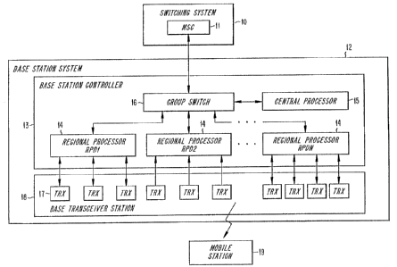
The following exemplary embodiments will be described by way of
illustration and not limitation. wth reference to Figure 1, a number of
regional
processor devices 14 (RPDI, RPD2...RPDn) are connected to the central
IS processor 15 through a group switch 16. The regional processing devices 14
are
connected to a number of transceivers (T'RX's) 17 located at the base station
sites. The connections 'between the regional processing devices 14 and the
transceivers 17 can be PCM lines, in accordance with standard GSM hardware.
For completeness, some GSM architecture surrounding the components
involved with the present invention is illustrated in Figure 1. To provide a
context for the invenfive method, it will be described with reference to the
GSM
system model CME 20 (a Pan-European digital mobile telephone system). CME
20, which is based on AXE technology, is F.ricsson's implementation of GSM.
A cellular radio communication system such as GSM may be basically
divided into two sections; a Switching System (SS) IO and, of interest to the
present invention, a Base Station System (BSS) 12. The base station system 12
provides an air interface with a plurality of mobile stations (MS's) 19. The
mobile stations 18 are the terminal equipment used by the subscriber.
2192934
w0 9ti35639 PCT1SE95/00664
-4-
The switching system IO and the base station system 12 are subdivided
into functional entities. The switching system 10 includes a Mobile Services
Switching Center (MSC) 11, which is the interface between GSM and the Public
Switched Telephone Network ~PSTN)(not shown).
The base station system 12 includes the regional processor devices 14
which provide the processing support for Lhe base station controller 13 and a
Base
Transceiver Station (BTS) I8, which is the radio equipment needed to serve one
cell. The base station transceiver I8 contains the aerial system, the radio
frequency power ampl~ers and aII the digital signal processing equipment
needed, including the transceivers i7.
The base station system 12 also includes a Base Station Controller (BSC)
13, which is the functional unit that controls and supervises the base station
transceivers i7 and the radio connections in the system. In the CME 20 System,
the base station controller I3 is implemented in a AXE 10 switch. The mobile
switching center 11 is responsible for set-up and routing of calls to and from
mobile subscribers. A llot of other functions are implemented in the mobile
switching center lI, e.g., authentication and ciphering.
Fach regional processing device 14 handles signalling and call supervision
(e.g., locating) over a 64 Kbit/s PCM time-slot for up to four (4), or in some
cases three (3), transceivers I7 under standard GSM system structure. The
number of transceivers per regional processor device can vary between one and
eight in current and envisioned implementations of GSM (while currently only
three or four are used). The maximum of four is not a hard limit.
In base station controller applications, the regional processor devices 14
are often referred to Transceiver Handlers (TRH's), thus the title of the
present
invention.
The configuration rule above (i.e., three to four transceivers per regional
processor device) is conventionally applied to all installed regional
processor
devices, with no regard to traffic (e.g., setting up, clearing and, to some
degree
2192934
WO 95135639 PCT/SE95/00664
-5-
the numbers of simultaneous calls (Erlang)) considerations. By applying such
considerations, some interesting factors become clear.
For a few regional processor devices, the risk for an overload is evident
(resulting in a risk for faulty call supervision, lost calls, etc). This goes
for
regional processor devices in metropolitan areas in particular, where all the
transceivers belong to heavy~uty channels which are likely to have traffic
peaks
coinciding in time. In such a case, occasionally one or two transceivers 17
might
be enough per transceiver handler 14.
On the other hand, for a large number of regional processing devices
IO (most likely the majority), the risk of too low a load is evident
(resulting in a
waste equipment expense and space). This is especially true in rural areas,
where
transceiver quantities are Large due to the large areas covered rather than
traffic
handling reasons. In such cases, a maximum number of twenty transceivers per
regional processor, for instance, might be appropriate.
~ For typical base station controller applications, a mixture of the cases
above is expected. That is, while same regional processor devices 14 are
overloaded at a certain time, the majority of the regional processor devices
14 are
poorly utilized. A better division of transceivers per regional processor
device
seems advisable. However, as the traffic varies in time, the conncclions
between
transceivers and regional processor devices can not be hard-wired for
optimization.
To solve these problems, a method and apparatus for load sharing
between regional processor devices is described next.
Initially, a number of transceivers are connected to each regional
2S processing device. With reference to the load situation shown in Figure 2,
assume the load of a first regional processing device RPD1 is rising, thereby
indicating potential load problems. To address the load problems, a load
monitor
is included in the central processor 15. The Load monitor 25 is best suited
for
software implementation.. This gives the best opportunities regarding
operation
and SIahStICS, while having low processing demands.
R'0 95135639 ~ _ PCTISE95/00664
The load sharing mechanism will now be described with references to the
process steps of Figure 3 (wherein the specific values are offered only by way
of
example):
(a) Each regional processor device reports the average (andlor peak)
load for an elapsed time, e.g., at i minute intervals (Step 31). For
example, a signal REP INT might be sent to a load monitor in the
central processor.
(b) The load monitor updates a load list (Step 32), determines which
transceiver has the highest load (step 33), and checks whether any
regional processor device has reported a toad above 80~ (iJPPER
LIM), for example (step 34). If no regional processor has a load
at or above the upper limit, the method returns to wait for more
Load reports (step 31).
(c) If a regional processor device is found to have a load at or above
an upper limit, the load monitor finds the regional processor device
with the lowest load (step 35), and checks whether there are any
regional processor devices with a load below 3096
(LOWER LII~, for example (step 36). If no regional processor
device is found to have a Load at or below the cower limit, then the
method returns to await the next set of load reports (step 31).
(d) If a regional processor device with a low load is found (step 3~, a
changeover of one transceiver connection from the regional
processor device with the highest load to the regional processor
device with the lowest Ioad is prepared ('f1 from RPDl to RPD2,
for exampie)(step 3~.
To make such a transfer as smooth as possible, the
following measures are taken: (i) transfer of recent
generations of reported measurement data (for transceiver
connection TRX Tl) from a first regional processor device
RPD1 to a second regional processor device RPD2, and
w0 95!35639 2 l 9 2 9 3 4 PCT~95J006bd
_7_
(2) loading of relevant cell data (for TRX TI) from the
central procrssor to the second regional processor device
RPD2. T'he measurement data is reported every 0.48
seconds, for example, and may include data on signal
strength of a received signal, signal quality (e.g., bit error
rate) of received signal, transmitting power used, signal
strength of up to six neighboring cells, information
regarding whether discontinuous transmissionlreception is in
use, etc.
(e) When the second regional processor device 12PD2 is prepared to
take over the connection T1 from the first regional processor
device RPDI, a change-over is executed (through the group
switch)(step 38).
(fj Steps (a) to (d) above (steps 33-38 in 1 figure 3) are repeated to
transfer a transceiver from ~ regional processor device with the
second highest load to a regional processor device with the second
lowest load, etc.
The change-over of transceiver connections from one regional processor
device 14 to another can be compared to when a redundant regional processor
device is connected at a regional processor device failure (which is a
capability of
current base station controllers). In this case, the disturbance an ttaffic is
estimated to be quite low. However, for the case described herein, the traffic
disturbance will be even less (perhaps virtually zero). The reason is that the
target regional processor device will be prepared by data transfers prior to
the
changeover.
The present invention has been described by way of example with respect
to a GSM system. It should be noted that the inventive concept may be
2192934
w0 95!35639 PC?'15E95/00664
-&
implemented and/or adapted to other systems. Also, variations from the
hardware and software disclosed herein are to be expected without departing
from
the scope and content of the invention, as measured by the claims appended
hereto.