Note: Descriptions are shown in the official language in which they were submitted.
7 ~ 93568
Vertical Bag Forming, Filling and Sealinq Machine
The present invention is directed to a vertical bag
forming, filling and sealing machine comprising a feed
system for a wrapping material forming the flexible tube
bags, a filling tube around which the wrapping material is
fed for the formation of a flexible tube and which serves
for filling of the material to be packed, a longitudinal
seam welding device and a cross seam welding device for the
formation of a lower and an upper cross weld seam at a
flexible tube bag.
Such machines are known. They operate in such a manner that
the wrapping material coming as flat web from a roll is
transported around the filling tube by means of the feed 25 system. During this transport the wrapping material is
formed as flexible tube whereafter the longitudinal seam is
welded. Hereafter, a lower cross weld seam is generated,
and the form bag is filled with the material to be packed
by means of the filling tube. Finally, the upper cross weld
seam is formed and the complete filled bag is separated
from the flexible tube.
With the known vertical bag forming, filling and sealing
machines one proceeds in such a manner that a cross seam
welding device simultaneously generates the lower cross
2 ~ 93568
-
weld seam of the flexible tube fed around the filling tube
and the upper cross weld seam of the filled bag which is
located thereunder.
The filling tube can have a round or rectangular shape. The
term "welding" which is used here is to comprise not only
the welding but also the sealing of the wrapping material
with a continuous seam and an interrupted seam.
Commercially available and customary foils are used as
wrapping materials, for instance polypropylene,
polyethylene, aluminum combinations, paper and other multi-
layer foils, which can be manufactured in various bag
formats. In addition to the welding devices corresponding
folding devices, air pushers or other members, for instance
knives, can be provided.
The known vertical bag forming, filling and sealing
machines operating in this manner have the disadvantage
that herewith the upper cross weld seams can be arranged
only with a relative large distance from the surface of the
filling material so that the flexible tube bags are formed
in a roof-like manner in their upper portion. The reason
for this is the fact that, when generating the upper cross
weld seam, the foil freely hanging at the filling tube is
applied with stresses by the inward movement of the weld
jaws. In other words, additional foil material has to be
fed from below by the inward movement of the weld jaws in
order to be able to put together the two foil sides over
the filling material. Normally, when putting together the
foil sides only angles with a value of up to 45 can be
obtained, i.e. smooth close sitting of the foils to the
filling material is not achieved. A relative large air
space rather remains over the filling material.
Indeed, it is also known to provide corresponding air
., 3 27 93568
pushers (air removers) which remove the undesired air.
However, even with these measures one did not reach sitting
close of the foil to the filling material in the upper
portion of the flexible tube bag. Accordingly,
disadvantages had to be accepted that the packed filling
material was able to dislocate within the flexible tube bag
whereby stacking problems etc. were generated.
The invention is based on the problem to provide a vertical
bag forming, filling and sealing machine of the kind
indicated above with which the upper cross weld seams at
the flexible tube bags can be provided as close as possible
to the surface of the filling material. In other words,
with such a machine flexible tube bags are to be
manufactured which have an air space over the surface of
the filling material which is as small as possible.
According to the invention this problem is solved with a
bag forming, filling and sealing machine of the above-cited
kind in such a manner that
a. the cross seam welding device is divided into two
separate units independent from one another of which
one generates the lower and one generates the upper
cross weld seam of a flexible tube bag;
b. the machine includes a lifting device for the filled
flexible tube bag not yet provided with the upper
cross weld seam;
c. the unit for the generation of the upper cross weld
seam is movable up and down; and
d. the lifting device and the unit for the generation of
the upper cross weld seam are driven and/or controlled
2 1 q35 68
-
in such a manner that the unit and the filled flexible
tube bag are lifted relative to the unit for the
generation of the lower cross weld seam and the
filling tube for the generation of the upper cross
weld seam.
Accordingly, the inventive solution is based on the
principle to lift the filled flexible tube bag not yet
provided with the upper cross weld seam together with the
unit for the generation of the upper cross weld seam
relative to the filling tube and the unit for the
generation of the lower cross weld seam in order to relax
the wrapping material forming the flexible tube bag and to
arrange more wrapping material in the range of the upper
cross weld seam so that the wrapping material can be moved
radially inwardly substantially stress-free by the unit for
the generation of the upper cross weld seam (weld or seal
jaws). Since enough material is present in this range one
succeeds in folding down the wrapping material close to the
surface of the filling material so that nearly no air space
remains over the surface of the filling material.
Accordingly, the upper cross weld seam can be arranged with
an especially small distance from the surface of the
filling material.
In order to realize the above-cited two movements of the
lifting device and of the unit for the generation of the
upper cross weld seam both members can have the same drive
means or different drive means. The velocities with which
both members are moved can be the same or different. In
this connection a number of special cases exist which are
described in the following.
In the simplest case the lifting device and the unit for
the generation of the upper cross weld seam are driven
~ 93568
and/or controlled in such a manner that both are lifted for
the same distance. Accordingly, in this case no relative
movement between the unit for the generation of the upper
cross weld seam and the surface of the filling material in
vertical direction occurs. However, this means that with
this embodiment the unit for the generation of the upper
cross weld seam has to be located relative close to the
surface of the filling material in order to achieve a
folding with a close fit in this range with a cross weld
seam arranged close to the surface of the filling material.
Accordingly, this embodiment is substantially suitable only
for machines with which a level of the filling material
being nearly always the same can be assured which is the
case with filling materials with a relatively stable shape
and/or with very exactly operating machines. Of course, in
this case the unit for the generation of the upper cross
weld seam approaches the flexible tube bag laterally and
puts the wrapping material over the surface of the filling
material from a lateral direction. If the levels of the
filling material are different problems can arise.
According to another embodiment of the invention which
should be the normal case for practice the lifting device
and the unit for the generation of the upper cross weld
seam are driven and/or controlled in such a manner that the
unit is lifted only over a part of the length of stroke of
the lifting device. In other words, according to this
embodiment during the lifting movement of the filled
flexible tube bag a relative movement between the surface
of the filling material and the unit for the generation of
the upper cross weld seam occurs in vertical direction. In
this case the velocity of the lifting movement carried out
by the lifting device is greater than that of the unit for
the generation of the upper cross weld seam since the
lifting device travels over a greater distance. Of course,
1~ ~ 3 5 6 ~
according to this embodiment the unit for the generation of
the upper cross weld seam has to be spaced from the surface
of the filling material in the lower position of the
lifting device and the unit so that in the upper end
position the unit for the generation of the upper cross
weld seam sits close to the filling surface. Accordingly,
with this embodiment the unit for the generation of the
upper cross weld seam lays against the surface of the
filling material from above since it also moves radially
inwardly during the lifting movement. Accordingly, the
wrapping material can be folded inwardly absolutely stress-
free in a nearly ideal manner.
Of course, whatever combinations of the two embodiments
described above are possible.
One solution is especially preferred according to which the
lifting device is lifted for a distance which corresponds
to the width of the flexible tube bag. This solution can be
used for both cases described above. In the first case also
the unit for the generation of the upper cross weld seam is
lifted through a distance which corresponds to the width of
the flexible tube bag. In the second case the unit for the
generation of the upper cross weld seam is preferably
lifted through a distance which corresponds to half of the
width of the flexible tube bag. It was already mentioned
that the unit for the generation of the upper cross weld
seam is preferably driven and/or controlled in such a
manner that it moves radially inwardly during the upward
movement. At the end of the upward movement of the lifting
device and of the unit for the generation of the upper
cross weld seam the unit for the generation of the upper
cross weld seam has also reached its end point of inward
movement so that the folding process of the wrapping
material is terminated and the cross weld seam can be
1 ~
-
7 ~ 93568
generated. In other words, then the two weld jaws or seal
jaws of the unit for the generation of the upper cross weld
seam have reached their radially innermost point and can
weld or seal together the two sides of the wrapping
material.
The unit for the generation of the upper cross weld seam
can be formed as true welding device or sealing device and
can include weld jaws or seal jaws for the generation of a
continuous weld seam or seal seam or for the generation of
an interrupted seam. Preferably, the unit is but provided
with a suitable folding device which can include one or
more folding members, for instance side folder. Such
folding members are known. By this, a correct folding in
the range of the upper cross weld seam is guaranteed.
Of course, for instance also two cross weld seams can be
located one upon the other in order to form a carrying
handle. In this case an aperture or a slot is produced in
the range between the two cross weld seams by means of a
suitable cutting means. It is always essential that the
wrapping material is folded in adaption to the filling
level in order to reach a packing as much as possible free
of air. As mentioned above, the air space over the filling
material is to be minimized in order to obtain a product
which is stable as much as possible which is accompanied by
a better packing density and a better ability of stacking.
According to an improvement of the invention the unit for
the generation of the upper cross weld seam is adjustable
relative to the lifting device with regard to the heigth.
This embodiment can respond to variations of the filling
level in a flexible manner, i. e. the unit for the
generation of the upper cross weld seam can be adapted to
the respective filling level, for instance in response to a
-- 21 93568
signal supplied by a sensor detecting the filling level, in
order to obtain a folding sitting close to the surface of
the filling material.
For the solution of the problem to provide an air space
over the surface of the filling material which is as small
as possible another embodiment of an inventive bag forming,
filling and sealing machine is characterized by the
features that
a. a folding device for the wrapping material is provided
at the upper end portion of the flexible tube bag
below the cross seam welding device;
b. the machine has a lifting device for the filled
flexible tube bag not yet provided with the upper
cross weld seam;
c. the folding device is movable up and down; and
d. the lifting device and the folding device are driven
and/or controlled in such a manner that the folding
device and the filled flexible tube bag are lifted
relative to the unit for the generation of the cross
weld seams and the filling tube for folding the
wrapping material.
This embodiment is substantially designed as the above-
described embodiment. Deviating from this embodiment is
substantially only the feature that an upwardly and
downwardly movable folding device is provided instead of
the upwardly and downwardly movable unit for generating the
upper cross weld seam. According to this embodiment the
unit for generating the upper cross weld seam can be formed
together with the unit for generating the lower cross weld
`-- 2 1 93568
seam, i.e. in a stationary manner in vertical direction.
Only the folding device is lifted together with the filled
flexible tube bag so that the wrapping material can be
folded on the surface of the filling material in a stress-
free manner in the upper range of the flexible tube bag.
Then, the real upper cross weld seam is generated by the
folding device, i.e. the flexible tube bag has a somewhat
longer upper end portion than with the above-described
embodiment. However, by the folding step the air is pressed
out of this portion so that, in spite of the upper cross
weld seam located at a higher position, a package is
achieved which is relatively stable with regard to its
shape.
Moreover, all the variants of the above-described
embodiment come also true for the present embodiment. As
mentioned above, the device designated with the first
embodiment as unit for generating the upper cross weld seam
carries out a true folding process while the upper cross
weld seam can be conventionally generated by a device which
forms not only the lower but also the upper cross weld
seam. Furthermore, according to this embodiment several
upper cross weld seams can be generated, too. In any case,
the folding device provides for a close sitting of the
wrapping material to the surface of the filling material
and thus causes the desired pressing-out of air.
Preferably, the folding device itself can include two
folding jaws and can be formed in a corresponding manner as
the above-described welding unit. However, also other
embodiments of folding devices can be used. It is only
essential that the folding device is lifted in connection
with the filled flexible tube bag.
In the following the invention is described by means of
` ~
2i 9356~
-
examples in connection with the attached drawing in detail.
Of the drawing
figure 1 shows a diagrammatic perspective representation
of a part of a vertical bag forming, filling
and sealing machine, wherein the lifting device
and the unit for generating the upper cross
weld seam are shown in a first lowered position;
figure 2 shows a corresponding representation as figure 1
according to which, however, the lifting device
and the unit for generating the upper cross weld
seam are shown in a second lifted position;
figure 3 shows a vertical section through a part of the
vertical bag forming, filling and sealing
machine of the figures 1 and 2, wherein the left
half of the figure shows the lowered and the
right half of the figure shows the lifted
condition of the lifting device and the unit for
generating the upper cross weld seam;
figure 4 shows a corresponding representation as
figure 3, however, wherein another embodiment of
the invention is shown;
figure 5 shows a horizontal section through the unit for
generating the lower cross weld seam; and
figure 6 shows a horizontal section through the unit for
the generation of the upper cross weld seam.
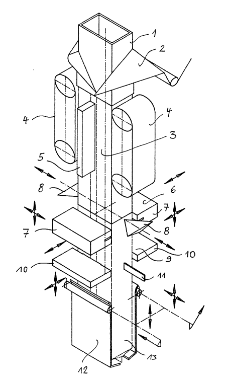
Figure 1 shows the essential components of a vertical bag
forming, filling and sealing machine which are of interest
for the present invention. A suitable wrapping material 2,
1~ 2~93568
consisting for instance of polyethylene, is laid around a
rectangular filling tube 1 by means of a feed system (not
shown) so that a flexible tube 3 is formed. Suitable
conveying means 4, which are shown as endless belts, move
the flexible tube intermittently in the figure from above
to below. A longitudinal seam welding device 5 welds
together the edges of the wrapping material.
A unit 6 for generating a lower cross weld seam (bottom
seam) is slightly spaced from the lower end of the filling
tube 1. This unit is associated with two side folders 8.
The unit 6 for generating the lower cross weld seam has two
weld jaws 7 which press the two sides of the formed
flexible tube 3 against one another by a radially inwardly
directed movement and weld the same. The side folders 8
have moved inwardly together with the weld jaws 7 so that a
proper rim results at the lower end of the flexible tube
bag.
Figure 2 shows the weld jaws 7 in their condition moved
together and the side folders 8 in their condition moved
inwardly.
After the generation of the lower cross weld seam the
filling material is filled into the flexible tube 3 which
is still open above. The filling device with a suitable
weighing device is not shown and does not form a part of
the present invention.
The upper cross weld seam of the flexible tube bag located
thereunder is generated simultaneously with the generation
of the lower cross weld seam. This upper cross weld seam
forms the upper end of the finished flexible tube bag which
is then separated from the flexible tube by means of a
suitable cutting device. As shown in figure 1, a unit 9 for
12
21 9356&
generating the upper cross weld seam (head seam) is located
below the unit 6 for generating the lower cross weld seam.
The unit 9 has also two radially inwardly and outwardly
movable weld jaws 10. This unit 9 is also associated with a
side folder 11.
The flexible tube bag already provided with a cross weld
seam at its lower end and filled with filling material 13
rests in a lifting device 12. For the generation of the
upper cross weld seam the flexible tube bag with the
filling material 13 and the unit 9 for generating the upper
cross weld seam are lifted so that the position shown in
figure 3 is reached. During the lifting movement the two
weld jaws 10 of the unit 9 for generating the upper cross
weld seam move radially inwardly so that the wrapping
material is folded radially inwardly. When terminating the
lifting movement the welding process is carried out. The
side folder 11 (only shown from one side) has been moved
inwardly in a corresponding manner. By the fact that not
only the flexible tube bag with filling material but also
the unit 9 for carrying out the welding process are lifted
a stress-free folding of the wrapping material in the upper
range of the flexible tube portion and a stress-free
welding are possible so that one succeeds in bringing the
wrapping material as close as possible to the surface of
the filling material. Accordingly, packages can be made
which are very stable with respect to their shape.
After the generation of the upper cross weld seam the
finished flexible tube bag is separated from the flexible
tube. The flexible tube bag falls on a suitable transport
belt by opening of the lifting device.
Figure 3 shows the operation of the lifting device 12 and
-13 21 9356~
-
of the unit 9 for generating the upper cross weld seam in
detail with a first embodiment. On the left side of the
figure the lifting device 12 and the unit are shown in the
lowermost position while they are shown in the uppermost
position on the right side of the figure. For carrying out
the folding and welding process the lifting device 12 lifts
the flexible tube bag provided with the filling material 13
for the distance B which corresponds to the width of the
flexible tube bag. Simultanously the unit 9 for generating
the upper cross weld seam is lifted for the distance B,
i.e. the right and left weld jaws 10 in the figure are
lifted. During the lifting movement of the unit 9 the two
weld jaws 10 move radially inwardly and reach the innermost
end position shown in the right half of the figure in which
the welding process is carried out. In this position which
corresponds to the uppermost position the weld jaws 10 are
slightly below the weld jaws 7 of the unit 6 for generating
the lower cross weld seam. In the lower most position shown
in the left half of figure 3 the weld jaws 10 are only
slightly above the surface of the filling material 13 so
that the folding process of the wrapping material is
substantially carried out by a true lateral movement of the
weld jaws 10. Since not only the lifting device but also
the unit 9 move for the distance B a single drive means 14
for both parts can be used. Finally, figure 3 shows the
lifting device 12 in a swang out condition.
The embodiment shown in figure 4 substantially corresponds
to that of figure 3 with the only difference that the
lifting device 12 and the unit 9 for generating the upper
cross weld seam move for different distances and thus with
different velocities. According to this embodiment the
lifting device 12 moves for the distance B, as with the
embodiment of figure 3, while the unit 9 moves only for the
distance B/2. In the lowermost position of the lifting
14` ~1 93568
device 12 and the unit 9 shown in figure 4 the unit 9 is
spaced from the surface of the filling material by a
distance of B/2. As shown in the right half of figure 4,
this distance has been nearly consumed in the uppermost
position of the unit 9 and of the lifting device 12. Also
in this case the two weld jaws 10 of the unit 9 move
radially inwardly during the lifting movement until they
reach the end position shown in the right half of figure 4.
One recognizes that in this embodiment the weld or fold
jaws lay from above onto the surface of the filling
material and do not carry out an exclusive lateral movement
as with the embodiment of figure 3. Accordingly, the
wrapping material can be adapted to the surface of the
filling material with close fit in a completely stress-free
manner.
Figure 5 shows a cross-section through the machine in the
range of the unit for generating the lower cross weld seam.
The two weld jaws 7 are shown in the closed position in the
upper half of the figure while they are shown in the open
position in the lower half. A drive means 15 provides for
the corresponding transverse movement of the weld jaws 7.
Furthermore, one recognizes triangularly shaped side
folders 8 which are moved inwardly in the figure from above
and from below in order to fold the wrapping material in a
suitable manner.
Figure 6 shows a cross-section of the machine in the range
of the unit 9 for generating the upper cross weld seam.
Also in this case the two weld jaws 10 are shown in the
closed condition in the upper range of the figure while
they are shown in the open condition in the lower range.
Furthermore, one recognizes the suspending flexible tube 3
which is folded radially inwardly by the weld jaws 10 from
both sides. A corresponding drive means 16 provides for the
1~ 2~ 93568
-
inward and outward movement of the weld jaws 10. The side
folder 11 consisting of two members is also shown.
The above-described example is also true for an embodiment
of the invention according to which a folding device is
provided instead of the liftable unit for generating the
upper cross weld seam. In this case, the member 9 is formed
by the folding device, and the member 6 is formed by a unit
for generating the lower and the upper cross weld seam.
Moreover, the same structure and the same operation are
present.
With the above-described embodiments shown in figures 1 to
6 it was emanated from the fact that the unit 6 generates
only the lower cross weld seam (bottom seam) of a flexible
tube bag which is not yet filled. However, it is clear that
this unit 6, in addition to this lower seam (bottom seam)
can also generate in a standardized manner an upper seam
(head seam) of the flexible tube bag thereunder. For this,
the unit 6 has preferably two double jaws including two
superposed weld jaws, respectively. In addition to the
upper cross weld seam produced with the unit 9 in an
inventive manner another cross weld seam positioned
thereabove is generated. Thereafter, a separation between
the two cross weld seams generated by the double jaws 7 is
carried out.
On principle, the unit 6 can only generate the lower cross
weld seam (bottom seam) of a flexible tube bag not yet
filled or this lower cross weld seam and an additional
upper cross weld seam (head seam) of a filled flexible tube
bag located thereunder. This is independent of the upper
cross weld seam generated by the unit 9 or independent of a
folding unit provided instead of this unit.
I6
21 93568
Furthermore, with the inventive machine the portion of the
flexible tube bag remaining above the upper cross weld seam
can be shortened arbitrarily by means of knives
additionally provided.