Note: Descriptions are shown in the official language in which they were submitted.
-- 21 93580
-- 1 --
Title: HANGER FOR LIFT TRUCK FORK
FIELD OF THE INVENTION
This invention relates generally to forks for material
handling trucks and more particular to devices to enable changes in the
5 lateral location of the fork with respect to the carriage of the material
handling truck.
BACKGROUND OF THE INVENTION
Fork lift trucks typically have a mast. A carriage is attached to
the mast. The material handling vehicle has powered means for elevating
10 the carriage along the mast. In order to carry loads, a generally L-shaped
fork is attached to the carriage. In many instances two such forks are
attached to the carriage and loads are carried by inserting the forks into a
pallet or other convenient device on which the goods to be handled are
positioned. In other instances, the goods themselves can be directly
15 contacted by one or more forks. When carrying articles which are
relatively long and tubular such as rolled carpets a single fork may be used
to carry the load.
With the variety of configuration and spacing of loads to be
carried on fork lift trucks, it is common to provide a means for the
20 adjustment of the location of the forks with respect to the carriage. If the
desired load is to be picked up with two forks then the spacing between the
forks may need to be adjusted to accommodate the particular pallet or
other configuration of the load to be carried. Where a single fork is to be
used such as in dealing with carpet rolls then one of the forks may be
25 removed from the vehicle and the single fork would then typically be
moved to the centre of the vehicle to evenly distribute the load on the
vehicle wheels.
Typically the carriage which travels vertically up and down
the mast comprises upper and lower mounting bars. When installing
30 forks on a carriage having upper and lower mounting bars, the forks are
normally provided with a pair of hook shaped hangers. The hangers
21 93580
extend toward the mast, that is, away from the load supported on the blade
of the fork. The hanagers will usually extend vertically with thje upper
hanger extending downwardly over the upper mounting bar and the
lower hanger extending upwardly over the lower mounting bar.
Typically, the upper mounting bar will be provided with a
series of locating elements. These may be in the form of holes or slots in
the upper mounting bar. Some type of interengaging structure such as a
pin is provided to engage with the slots or holes in the upper mounting
bar. Conventionally, the pin assemblies which engage with the holes in
the upper mounting bar of the carriage, require additional parts to be
welded to the hanger or make use of some type of relatively
unsophisticated lever action which can be damaged in use.
It is apparent therefore that there is a need for a simplified
device which provides positive locking action to maintain the fork in its
desired lateral location. It is also desired that the device may work directly
with the hanger rather than being separately formed and welded to the
hanger.
SUMMARY OF THE INVENTION
An upper hanger for mounting a lift truck fork to an
elevatible lift truck carriage of the type having upper and lower mounting
bars is provided. The fork comprises a blade and a shank. The fork has an
upper hanger. The upper hanger has a a first surface for contacting the
upper mounting bar of the carriage. The hanger comprises a pin for
moving in a generally vertical direction between a first position in which
the pin projects from the hanger to engage the upper mounting bar and a
second position in which the pin is recessed within the hanger so that the
pin does not engage the mounting bar. The hanger comprises guide
means to guide the pin for longitudinal movement between the first and
second positions as well as biassing means to urge the pin to the first
position. The hanger also comprises a second surface which is remote
from the first surface with the pin extending through the second surface.
The second surface is located at an angle to the direction of longitudinal
2 ~ 93580
movement of the pin. The pin includes a boss. The boss has first retaining
means while the hanger has second retaining means. The first retaining
means and the second retaining means interengage for releasably retaining
the pin in the second position.
5 DESCRIPTION OF THE DRAWINGS
Preferred embodiments of the invention are described below
with reference to the attached drawings, in which:
Figure 1 is a schematic side view of a fork in accordance with
a preferred embodiment of the invention illustrating the attachment
10 between the fork and the mounting bars of a carriage;
Figure 2 is a perspective view of the upper mounting bar of
the carriage as illustrated in Figure 1;
Figure 3 is a perspective view of the upper hanger of the fork
of Figure 1;
15Figure 4A is a vertical sectional view of the hanger of Figure 3
with the pin in a first position;
Figure 4B is a view the same as Figure 4A but with the pin in
a second position;
Figure 4C is a view similar to Figure 4B, but showing an
20alternate embodiment;
Figure 5A is a view of a pin of the hanger of Figure 4A.
Figure 5B is a view similar to the view of Figure 5A but
showing an alternative structure for the pin;
Figure 5C is a view similar to Figure 5A showing a further
25alternative structure for the pin shown in Figure 5A;
Figure 6A illustrates the boss of the hanger shown in Figure
4A;
Figure 6B shows an alternative structure for the boss as
illustrated in Figure 6A;
30Figure 6C illustrates a further alternative structure for the
boss as shown in Figure 6A;
Figure 6D illustrates a clamp for use with the boss of Figure
21 93580
-4 -
6C;
Figure 6E shows an aternate structure to the boss as shown in
Figure 6A;
Figure 6F illustrates a further alternative of the boss as shown
5 in Figure 6A, and
Figure 7 is a rear view of the hanger of Figure 3.
The fork 10 illustrated generally in Figure 1 comprises a
substantially vertical shank 12 and a substantially horizontal blade 14.
Attached to the shank 12 there is an upper hanger 16 and a lower hanger
1018. The hangers 16 and 18 may be attached to the shank 12 such as by
welding. The welds are shown at 20 in Figure 1.
The hangers 16 and 18 comprise portions which extend from
the back of the shank that is away from the blade and toward the carriage
of the material handling vehicle typically a lift truck vehicle.
15The hanger 16 comprises a hook 22 which extends
downwardly to engage an upper mounting bar 30 of the lift truck vehicle.
The lower hanger 18 also comprises a hook 24 which engages a lower
mounting bar 32 of the lift truck vehicle. The two mounting bars 30 and
32 are attached to the carriage of the lift truck vehicle. The remainder of
20 the carriage and the mast to which the carriage is affixed are not shown as
these do not form part of the current invention. The structure of the
carriage, its supporting mast and the means for elevating the carriage may
all follow typical designs.
Figure 2 illustrates the upper mounting bar 30 of the material
25 handling vehicle carriage. The upper mounting bar comprises a
substantially horizontal surface 34, a surface 36 extending at a slight angle
to surface 34 and a surface 38 which extends substantially horizontally. The
two surfaces 36 and 38 together with the forward facing surface 40 of the
mounting bar define a rib 42 extending along the top edge of the mounting
30 bar 30. The rib 42 is provided with a plurality of slots 44. The slots 44 act as
positioning stops to provide a plurality of fixed locations for the location of
forks along the mounting bar.
21 93580
- 5 -
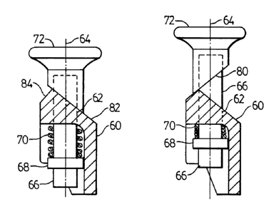
Figure 3 illustrates the upper hanger 16 prior to welding the
upper hanger 16 to the shank 12 of the fork 10. The hook 22 defines a first
surface 50A and 50B. The surface 50A and 50B contacts the surfaces 34 and
36 of the mounting bar 30 shown in Figure 2. The angle between surfaces
50A and 50B is the same as the angle between surfaces 34 and 36 of the
mounting bar 30. The upper hanger 16 comprises a body 60. The body 60
defines a bore 62 which extends generally vertically through the body 60.
The bore defines an axis 64 for guided longitudinal movement of a pin 66
shown in Figure 4A and 4B. The pin 66 is movable from a first position
shown in Figure 4A to a second position shown in Figure 4B. The pin
comprises a land 68. A spring 70 acts between the land 68 and the body 60
of the hanger 16 to bias the pin to the first position shown in Figure 4A.
To move the pin to the second position as shown in Figure 4B, the spring
must be compressed as shown in Figure 4B.
The pin advantageously includes a boss 72. The pin may be
threaded at its upper end as shown in Figure 5A at 76. The boss 72 may
also have an internal thread 78 as shown in Figure 6A so that the pin 66
may be threaded into the boss 72.
The pin 66 as illustrated in Figure 5A is most advantageously
round in cross-sectional configuration. Thus, the pin may be rotated about
the axis 64 as desired. However, the pin may also have other
configurations such as square, rectangular and the like. Where the pin is
round, the boss may be attached to the pin so that the boss rotates relative
to the pin or so that the boss does not independently rotate relative to the
pin. As will be explained subsequently, where the pin is not round, it is
advantageous to affix the boss to the pin to permit relative rotation
between the pin and the boss. To assist assembly of the pin and spring, the
boss is a separate piece. Where other assembly structure is available the
boss may be a part of the pin.
Alternate forms of pin, boss configuration are shown in other
figures. Figure 5B illustrates a pin 166 that may be used in association with
a boss 172 illustrated in Figure 6B. Rather than using threads to connect
-
6 21 93580
the boss to the pin, a pin may be passed horizontally through the wall 168
illustrated in Figure 5B. Aligned apertures 170 may be provided in the boss
172 and a pin may then be force fit into the aligned aperture to connect the
boss 172 to the pin 168.
Pin 266 illustrated in Figure 5C involves a groove 268 at the
upper portion thereof. The pin 266 may be used in association with the
boss 272 illustrated in Figure 6C. The boss 272 has a groove 270 which in
use is aligned with the groove 266. A U-shaped clamp 274 illustrated in
Figure 6D may be used to connect the boss 272 and the pin 268. A
connection of this type would then permit relative rotation between the
boss 272 and the pin 266. Pin 266 may therefore be circular in its cross-
sectional configuration or rectangular or indeed any other shape of
convenience.
Alternate forms of bosses 372 and 472 are illustrated in Figure
6E and 6F respectively. The boss 372 does not have a circular top but rather
a side handle extending from one portion of the boss. The boss 472
comprises a twist knob configuration at its upper portion. The connection
between the bosses 372 and 472 and their respective pins may use any of
the connections previously discussed in association with Figures 6A, 6B,
6C and 5A, 5B and 5C.
As illustrated in Figures 3, 4A and 4B, the boss 72 comprises a
surface 80. The surface 80 is an essentially planar surface formed by
passing a plane at an angle to the axis 64.
The housing 60 of the upper hanger comprises a second
surface 82. The pin 66 extends beyond the surface 82 when the pin is in
both the first position and the second position. When the pin is in the first
position as shown in Figure 4A, the pin 66 projects from the hanger 16 so
that it may engage with one of the slots 44. With the pin 66 engaging with
the slot 44 then horizontal relative movement between the hanger and
the mounting bar 30 is not possible. Thus, with the pin in the first
position the fork 10 cannot be moved laterally relative to the hanger 30.
When the pin is in the second position as shown in Figure
7 21 93580
4B, the pin is recessed within the body 60 of the hanger 16. With the pin
in the recessed position then the hanger and the fork to which the hanger
is welded may be moved horizontally relative to the mounting bar 30 for
positioning as desired. When the fork is in the desired position the pin is
5 allowed to move to the first position.
In order to facilitate maintaining the pin in the second
position the boss 72 interacts with the body 60 of the hanger to maintain
the pin 66 in the second position when the parts are aligned in a particular
configuration.
10As seen in Figure 3, the hanger 60 comprises an auxiliary
surface 84. The interreaction between the surface 80 of the boss 72 and the
surfaces 62 and 84 of the hanger can be appreciated from review of Figures
4A and 4B.
When the pin is in the first position as shown in Figure 4A
15the surface 80 of the boss 72 lies in contact with the surface 82 of the hanger
body 60. Thus the surface 80 provides a contact surface for contacting the
surface 82. This limits downward movement of the pin 66 under the
urging of the spring 70 as shown in Figure 4A.
When it is desired to move the pin to the position shown in
20 Figure 4B, the boss 72 is grasped by hand. The boss is pulled upwardly by
hand while rotating the boss through 180~. As shown in Figure 4, surface
80 of the boss 72 extends from the upper left, downwardly to the lower
right. When turned 180~ as shown in Figure 4B, the surface 80 extends
from the upper right to the lower left. When in that orientation the
25 surface 80 may then engage with the surface 84. Once the surface 80 of the
boss 72 interengages with the surface 84, any downwardly movement of
the pin 66 under urging of the spring 70 as shown in Figure 4B, is
eliminated. Thus, with the boss turned as shown in Figure 4B, the pin is
retained in the second position. In this manner the contact surface 80
30 comprises the first retaining means while the auxiliary surface 84
comprises a second retaining means. The first and second retaining means
interengage to maintain the pin in the second position despite the urging
8 2~ 93580
of the spring 70. As shown in Figure 4B, when the fork has been moved to
the desired position, the boss is rotated through 180~ to the orientation
shown in Figure 4A. The spring will then urge the pin to the first position
as shown in Figure 4A thus preventing any further horizontal movement
5 of the fork relative to the mounting bar 30.
As shown the surfaces 82 and 84 of the body 16 may intersect
with the axis 64 at the same acute angle. This means that surface 80 will
then bear on the surface 84 through whatever area is provided by surface
84 and that portion of surface 80. However, as an alternative, surface 84
10 need not extend at the same acute angle to the longitudinal axis 64. If the
surface 84 intersects the axis of longitudinal movement 64 at right angles,
for example, pin 66 will still be retained in its second position. This is
illustrated in Figure 4C. Surface 84A is substantially horizontal. For co-
operation with surface 84A, boss 72 may advantageously be provided with
15 horizontal surface 80A.
Desirably, the upper hanger 60 should be in a configuration so
that it may be forged. Forging of the block of material is considerably
cheaper than machining a cast block. Forged material will also have the
strength typically required in lift fork components. All of the surfaces
20 explained above may be comprised in a forging operation. The bore 62
may be formed during the forging operation. The techniques of forging
such parts are well known to those familiar with this art.
It is intended that the foregoing description be interpreted as
illustrative rather than in a restrictive sense. Accordingly, variations to the
25 structures described herein may be apparent to persons skilled in the art of
lift truck forks in adapting the present invention to specific applications. It
is intended that this specification intend to cover any such variations
insofar as they are within the spirit and scope of the following claims.