Note: Descriptions are shown in the official language in which they were submitted.
2 1 ~3670
1~0 95/35441 PCT/~IJ95/00367
AUXILIARY INJECTOR
TECHNlCal FIFI n
This invention relates to fuel injection systems for internal combustion
engines.
5 BACKI~ROUN~ ART
Fuel injection systems for intemal combustion engines can be adapted to
supply liquid fuels to the inlet manifold for each cylinder of the engine. This
system is known as multi-point liquid fuel injsction. By suitable control of theoperation of the injectors accurate amounts of liquid fuel can be supplied
1 O directly to each cylinder dependi"g upon engine conditions and demand
~,hdrd~,ttsri:,lics fom/dpolistltivi) and combustion in the cylinder.
There is a problem in that for liquid fuel injection to be accurate the fuel in the
injectors adjacent the injection point must be liquid at all times. The
e"v;~"",t",l around each cylinder, however, can at times during engine
15 operation be very hot and such a temperature in this region is not conducive
to injection of a liquid fuel which has a low boiling point.
One particular time in which serious problerns can occur is when an engin
has been tumed off for some time after running and the fuel rails, body of the
inlet manifold and the injector or injectors have heated consid6,dbly to the
20 stage that the liquid fuel in the injectors and even in the fuel rails has
vaporised so that the rails are full of gassous fuel rather than liquid fuel. This
condition may be known as heat soak conditions. When it is desired to restart
such an engins, the injectors which are designed to supply pressurised liquid
will not supply sufficient fuel in the form of a gas and such an engine cannot
2!; easily be started. Operation of a fuel pump to circulate fresh fuel through the
fuel rails and injectors is necessary for some con~iderdl,le time, perhaps 15 or30 seconds, before sufficient fresh fuel has been pumped into the fuel rail and
injectors to cool them and to supply liquid fuel to the injectors to enable
starting of the engine.
30 Another problem can exist where an engine is operated on a dual fuel system.
That is, the engine has perhaps both a LPG and a petrol supply and is desired
to change from one fuel to the other. Where the change is from petrol to LPG
the much higher pressure LPG easily replaces the petrol but when the change
_ _ , . . , _ . , _ _ _ . .
219367~1 RECÉIVED52/74~R~96;
is from LPG at a higher pressure to petrol at a lower pressure there is a
collsideldble time, perhaps in the order of two minutes, where the pressure is
still too high to admit petrol but the LPG pressure is not 1 l Iclil Itdil ~ed because of
lack of flow of LPG and hence is not high enough to prevent vdl,orisalion of
5 the fuel and again ~qas rather than liquid is supplied through the injectors.
It is the object of this invention to provide an arrangement by which an engine
can be started in what may be termed heat soak conditions and also to
provide dlldllyelllelll:~ where power can be illaillldil,ed during changeover
from one fuel to another in a dual fuel system.
10 DISCLOSUF(F OF THE INVFNTION
In one form therefore the invention is said to reside in an auxiliary injector
andll!Jelllenl in a dual fuel supply system for an internal combustion engins,
the dual fuel supply system col~ll.rising a main fuel supply system to supply atleast one of the fuels using a main liquid fuel injector or injectors into at least
15 an inlet manifold adjacent each engine cylinder of the engine, and an
auxiliary fuel supply system, wherein the inlet manifold includes a throttle
body and the inlet manifold is divided do~ a,ll of the throttle body to
supply air to each of the cylinders of the internal combustion engine, the
auxiliary fuel supply system including at least one injector for one of the fuels
20 mounted in or adjacent the throttle body upstream or d~ a, 1 l of a throttle
valve in the throttle body and adapted to supply fuel at times when the main
injector or injectors cannot supply sufficient fuel.
Hence it will be seen by this invention that there is provided an auxiliary fuelinjector located in the main inlet air stream at a point some distance from the
25 engine block, where temperatures are not so harsh, as an altemative fuel
supply system.
- Because of its positioning adjacent the throttle the auxiliary injector may be called a throttle body injector.
In one preferred e" II,odi~ , ,I the main fuel supply system may be a multi-
30 point fuel injection alldllgelllt:lll and there may be individual injectors for each
cylinder operating on petrol, LNG, CNG or LPG. Alternatively the fuel supply
system may be a single injector system operating on petrol, LNG, CNG or
LPG.
AMENDED SHEEl
IPEAIAU
PCT/AU 9 5 / 0 0 3 6
219367~ RECEIVED 2 7 MAR 19'
~ 2/1
The fuel for both the main fuel supply system and the auxiliary injector of thisinvention may be a single fuel vehicle which may be LPG, natural gas or
petrol or some other fuel.
~MENDED SHEET
IPEA/AU
WO 95/35441 2 ~ 9 3 6 70 PCT/AlJ9~;/00367
A' "..'i~cly the invention may be applied to a dual fuel vehicle such as one
which is operahng on petrol and LPG or any other two fuels. In the dual fuel
system the auxiliary injector may be supplied with petrol or LPG.
The auxiliary injector when it is operated on LPG or natural gas may be either
5 a liquid fuel injector or a gaseous fuel injector.
If the auxiliary injector is operated on LPG or LNG as a gaseous fuel injector
the source of gas may be a vaporiser / regulator a,ldngemellL supplied with
liquid fuel from the fuel tank.
AILt~ toly the gaseous fuel may be obtained directly from the vapour space
10 in the top of the LPG or CNG fuel tank. Such a gas will be at the vapour
pressure of the fuel in the tank and this pressure will be sufficient to enable
supply as a gas to the injector and may need throffling back before supply to
the auxiliary injector. It may be necessary to use a pressure regulator on the
vapour supply line to the auxiliary injector.
15 When injechng through the auxiliary injector in either the liquid or gaseous
state the quanbty can be dtlLt:lll ,i"ed by ~ '~ " ,i" ~ of the pressure or
pressure and Ltllllp61 Ire and the use of suitable look - up tables in an
electronic controller for the engine.
As discussed above the auxiliary injector is used in a first circumstance when
~0 the temperahure or pressure or both in individual injectors is such that it is
likely that fuel has vaporised in the injectors. That is, there are some fomm ofheat soak condihons which are being caused by a hot engine.
The other circumstance in which the auxiliary injector may be used is in a dual
fuel engine when changing over from a higher pressure fuel to a lower
25 pressure fuel.
The auxiliary injector alldng~ ''L for liquid fuel may use one or two injectors
and these injectors may be angled to the direction of elul 1~ ~ of the inlet
manifold to direct fuel towards the throffle when mounted before the throffle
and directed at a baffle plate when mounted after the throttle to in each case
30 provide good mixing and vapol;f ~ of the fuel.
In one particular t:lllbudi"~llL there may be both LPG and petrol supplied to
the auxiliary injector with suitable valving to ensure only one of the fuels canbe supplied at a time so that if the dual fuel engine has no petrol at all then it
_ . .. . .
WO 95/35441 2 t 93 6 7 0 PCT/AU95100367
can still be operated on LPG even in heat soak conditions.
Where an auxiliary injector a"dnger"c3"1 according to this invention is to be
installed into a vehicle at time of manufacture a suitable construction of the
throffle body may be provided to include a mounting alldllye~ lll for the one
5 or more auxiliary injectors and a suitable fuel suppiy from the fuel supply line
for the englne.
Where the auxlllary injector is to be installed into a motor vehicle at the time of
change over from a single fuel injection engine to a dual fuel injection engine
there may be provided an adaptor ring which is fiffed Into the throffle inlet pipe
10 from the air cleaner and the injector may be mounted into the adaptor ring.
Once again a suitable supply can be provided from either the petrol supply
line or the LPG supply line.
Suitable electronic control means may be provided in the vehicles electronic
control unit to provide for actuation of the auxiliary injector at required times.
15 The invention therefore provides an auxiliary fuel supply which can be an
injector located on a throffle body adaptor upstream or l.'~ ... I~ll~dlll of the
throffle body of an intemal combustion engine. The injector may be a
standard petrol injector with relatively high flow c- "'ig IrAtiorl to cover as high
loads and engine speeds as possible. Its housing may be designed so that
20 the spray of the injector is directed towards the throffle valve. This will assist in
Vd,Uoli:iill9 petrol which is important to achieve relatively good fuel distribution
into each cylinder.
When heat soak conditions of the engine are detected the vehicle's electronic
control unit will energise the throffle body injector or auxiliary injector
25 operating on petrol by rAIc~ 9 the necessary fuel requirements and
consiclelilly the amount of fuel for a single injector only. If necessary, two
throffle body injcectors or auxiliary injectors can be used to cover a wider
operating range. This dllcdllgelll~lll will assist in providing fuel to the engine
and starting it running. At the same time as operating the auxiliary injector,
30 LPG or petrol fuel pumps can be operated to recirculate fuel to cool the
injectors and fuel rails of the main injection system but the actual Injectors are
not energised during this period.
When the electronlc control unit receives a signal that indicates that there is
no more vd~J~JIiadtion due to cooling of the recirculation fluid or a
PCI'/AU 9~ / h o~ fi 7
2~q367a RECEIVED 2 ~ 6
~ s
pr~dul~" "ined time has elapsed the thronle body injector can be stopped and
multi-point petrol LNG, or LPG operation can be used.
During the period that the auxiliary injector may be running which may be up
two minutes there may be some loss of power due to the limited fuel delivery
5 through one injector. Two injectors may be used, however, to overcome any
power loss during that period.
The thronle body injector may only be used when a heat soak condition is
detected or in a dual fuel engine upon change over from a higher pressure
fuel to a lower pressure fuel. When an engine is cold or there is no heat soak
10 conditions cranking and running will be as normal with the main or multi-point
injectors.
The'auxiliary injector may also be used to assist the changeover from a high
pressure fuel such as LPG to a lower pressure fuel such as petrol. During
changeover the auxiliary injector is running on petrol simultaneously with the
15 multi-point injectors to bleed the vapour of LPG into the inlet manifold. Theelectronic control unit may adjust the fuel injecffon in the thronle body injector
or auxiliary injector and the multi-point LPG injectors by r"u"itu~ i"g the
feedback from the exhaust oxygen sensor. Care is taken so that the purging
- of LPG is done as quickly as possible by reducing the amount of fuel from the
20 thronle body injector and achieving a relatively fast changeover. During the
changeover period the pressure in the fuei rail is monitored continuously so
when the pressure drops close to the petrol pressure it will switch to petrol
multi-point injection and the throttle body injector will be switched off.
Hence in an " -" ~/o form the invention may be said to reside in a method
25 of operating a fuel supply system for an internal combustion engine
co",p,i~i"y a main fuel supply system and an auxiliary fuel supply system
including the steps of d~ ,."i"i"g times when the main fuel supply system is
unlikely to be or is not delivering sufficient fuel for efficient operation of the
engine and injecting fuel into an inlet manifold of the engine at a point remote30 from the engine by the use of the auxiliary fuel supply system which includes an auxiliary injector as discussed above.
This then generally describes the invention, but to assist with ul Idel :,ldn~lil ,g
the invention reference will now be made to the accompanying drawings
which show preferred embodiments of the invention.
~MENDED SHEET
IPE~AU
2 1 9 3 67 û R E C E 1~ E~D 2~ ~lA3R ~996
5/l
BRIEF DESCRIPTION OF THE DRAWINGS
~MENDED SHEET
IPEA/AU
WO 95135441 2 7 9 3 6 7 0 PCT/AU9~/01)367
In the drawings;
FIG 1 shows a schematic view of a fuel injection a"d"ye",~r,l
according to this invention using a single fuel,
FIG 2 shows a dual fuel injection ar,d"yt~",t:"l including an auxiliary
5 injector of the present invention,
FIG 3 shows a single fuel injection alldllyeu)t1lll including an
auxiliary injector of the present invention,
FIG 4 shows an ~ , dual fuel injection dllmlgellltslll including
an auxiliary injector of the present invention,
FIG 5 shows a single fuel injection a"d"y~",~"~ including an
auxiliary injector of the present invention utilising a mixer - vaporiser, and
FIG 6 shows a single fuel injection a"d"ge"~e"l including an
auxiliary injector of the present invention utilising vapour direct from the fuel
tank.
15 BEST MODE FOPi CARRYING OUT THF INVENTION
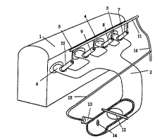
Now looking more closely at the drawings and in particular FIG 1 it will be
seen that an engine 1 shown s..l ,~" 'Iy has an inlet manifold 2 which is
divided into individual inlet ducts 3, 4, 5 and 6, one for each cylinder. Fuel
injectors 7, 8, 9 and 10 supply fuel from a fuel rail 11 into each injector. The20 fuel may be petrol or LPG. Electrical wiring (not shown) from an electronic
controller (not shown) is provided to actuate the injectors as required. Also
not shown is a return iine from the injectors and rail to the fuel tank.
The inlet manifold 2 includes a throttle valve 12 and upstream of the throffle
valve 12 there is an auxiliary injector 13 which is supplied with fuel by line 15
25 from a supply line 16 which provides fuel to the fuel rail 11. The auxiliary
injector 13 has a nozle 14 directed into the inlet manifold 2 upstream of the
throttle valve 12. The auxiliary injector 13 is also actuated by the electronic
controller.
It will be noted that the position of the auxiliary injector 13 upstream of the
30 throttle valve 12 is sc""~ hdl remote from the engine 1 and therefore is not so
subject to the very high heating conditions which can occur on the individual
~1~0 9S/35441 2 1 9 3 6 7 0 PCI/AU95/N367
inlets 3, 4, 5 and 6. For this reason even if fuel has vaporised in the injectors
7, 8, 9 and 10 and even in the rail 11 liquid fuel can still be provided throughthe auxiliary injector 13 to enable starting of the engine in hot condibons.
Once the engine has been started using the auxiliary injector then sufficient
- 5 fuel can be circulated through the injectors 7, 8, 9 and 10 to cool them or the
injectors can be operated to purge gas from them and supply liquid fuel. Once
the main multi-point injectors are operating correctly then the auxiliary injector
is stopped.
FIG 2 shows a schemabc dlldll9elllt~11t of a dual fuel engine operating on LPG
1 0 and petrol and using an auxiliary injector according to this invenbon. Theengine 20 has a inlet manifold 21 which is divided into four individual
manifolds 22 each of which supply air to a cylinder in this case a four cylinderengine. Injectors 23 supply fuel as requiredl to each individual inlet duct so
that it can get into individual cylinders. During normal operabon on either LPG
1 ~ or petrol excess fuel is recirculated through an inlet fuel rail 27, the injectors
23 and an outlet fuel rail 33 to maintain cooling of the injectors 23. In the case
of LPG, LPG pump 24 pumps fuel from the tank 25 through LPG feed line 26
into the inlet fuel rail 27 and through each of the injectors with the excess fuel
passing through the outlet fuel rail 33 and the pressure regulator 29 and back
through LPG return line 28 to the LPG tank. Similarly with petrol operation,
petrol pump 30 pumps fuel through petrol feed line 31 from the tank 35 to the
inlet fuel rail 27 and through the injectors 23 and out through the outlet fuel rail
33 and through the petrol reburn line 34 to the petrol tank 3~. A petrol
pressure regulator 39 in the retum line 34 controls the pressure in the petrol
circuit.
A petrol feed line 36 from the main petrol feed line 31 supplies an auxiliary
injector 37 in the inlet manifold 21 upsbream of the throttle valve 38. A branchline 32 from the petrol feed line 36 to the petrol retum line 34 upstream of theregulator 39 controls the pressure in the auxiliary injector feed line.
Fig 3 shows an alldll~ lllulll of a single fuel engine operating on a high
boiling point fuel such as petrol.
In this drawing the same reference numerals are used as in Fig 2 for the
common cu",~,one"ts.
The high boiling fuel such as petrol is stored in a tank 40 and is supplied to
WO95/35441 2 1 q3~70 PCT/AU95100367
the inlet fuel rail 42 by means of fuel supply line 41. After flowing through
each of the injectors excess fuel passes out through outlet rail 43 and outlet
fuel line 44 back to the tank 40. A petrol pressure regulator 49 in the retum
line 44 controls the pressure in the petrol circuit.
5 A petrol feed line 46 from the main petrol feed line 41 supplies an auxiliary
injector 48 which is d ... ,at,t~d", of the throttle 38 in the inlet manifold 21. A
branch line 47 from the petrol feed line 46 to the petrol return line 44 upstream
of the regulator 49 controls the pressure in the auxiliary injector feed line.
At times where there are heat soak conditions in the engine and the injectors
1 0 23 cannot supply sufficient fuel through the inlet pipes 22 to the engine then
the auxiliary injector 48 may be used to supply sufficient fuel.
A baffle 49 may be provided to efficiently disperse the injected fuel from the
injector 48.
Fig 4 shows a dual fuel engine in which the auxiliary injector 50 is a flow
15 through type injector supplied on fuel line 51 from fuel supply line 52 with
excess fuel passing through fue! retunn line 53 to main fuel retum line 54 and
pressure regulator 56 into the fuel tank 55.
In this e",l,odi" ,c:"l the injector 50 is upstream of the throttle 38 in the inlet
manifold 21.
20 Fig 5 shows an e",l,o-li",~"l of LPG or LNG fuelled vehicle which uses a
\,dl,o,ise,i~yulator 60 to vaporise liquid fuel supplied by line 61 from main
fuel line 62 and then to supply gas through line 64 to gas injector 65.
The gas injector 65 is d~J.nlatl~dlll from the throttle 38 in the inlet manifold 21.
Fig 6 shows an t:"lbo-li",~"~ of a LPG or LNG fuelled engine in which the
25 auxiliary injector 70 is a gas type injector and is supplied by fuel from the gas
line 71 which extends directly from the vapour space 72 above the fuel in the
fuel tank 25.
As there is gas in the vapour space i2 of the tank 25 in equilibrium with the
liquid in the tank there would be sufficient gas pressure to supply gas to the
30 injector 70. Optionally there may be a pressure regulator 74 in the gas supply
line 71.
WO 95135441 2 1 9 3 6 7 ~ PCT/AU95/00367
It will be seen that by this invention there is provided an alldllg~ l whereby
use of the an auxiliary injector in the throttle body of an internal combustion
engine gives easier hot start and fuel changeover conditions.
Throughout this -r ~' ~" " I and the claims that follow unless the context
requires otherwise, the words 'comprise' and 'include' and variations such as
'cc""~ ,i"y' and 'including' will be ulldel~tu.)d to imply the inclusion of a
stated integer or group of integers but not the exclusion of any other integer or
group of integers.
, ,, .. . ;