Language selection

Search

Patent 2193785 Summary

Third-party information liability

Some of the information on this Web page has been provided by external sources. The Government of Canada is not responsible for the accuracy, reliability or currency of the information supplied by external sources. Users wishing to rely upon this information should consult directly with the source of the information. Content provided by external sources is not subject to official languages, privacy and accessibility requirements.

Claims and Abstract availability

Any discrepancies in the text and image of the Claims and Abstract are due to differing posting times. Text of the Claims and Abstract are posted:

  • At the time the application is open to public inspection;
  • At the time of issue of the patent (grant).
(12) Patent Application: (11) CA 2193785
(54) English Title: MOLDED ELECTRODE AND METHOD OF MANUFACTURE
(54) French Title: ELECTRODE MOULEE ET METHODE DE FABRICATION
Status: Dead
Bibliographic Data
(51) International Patent Classification (IPC):
  • A61B 5/0408 (2006.01)
  • A61B 5/0416 (2006.01)
(72) Inventors :
  • GUSAKOV, IGNATY (United States of America)
(73) Owners :
  • GRAPHIC CONTROLS CORPORATION (United States of America)
(71) Applicants :
  • GRAPHIC CONTROLS CORPORATION (United States of America)
(74) Agent: FETHERSTONHAUGH & CO.
(74) Associate agent:
(45) Issued:
(22) Filed Date: 1996-12-23
(41) Open to Public Inspection: 1997-07-25
Availability of licence: N/A
(25) Language of filing: English

Patent Cooperation Treaty (PCT): No

(30) Application Priority Data:
Application No. Country/Territory Date
08/590,093 United States of America 1996-01-24

Abstracts

English Abstract


A conductive medical electrode formed from a moldable, conductive material
such as carbon-filled plastic. In one embodiment, the electrode is an integral,
conductive electrode including a stud adapted to detachably couple the electrode to a
lead wire and a body integral with the stud. The body has a face disposed opposite the
stud, for contacting a patient, which has a grooved pattern formed therein. The
grooved pattern increases the surface area of the electrode in contact with a
conductive adhesive and increases the conductivity between the patient and the
electrode. A second embodiment features a two-piece, conductive electrode including
an electrically conductive stud and an electrically conductive substrate having an
opening formed therein and attached to the stud. The opening formed in the body
creates a cavity which aids in retaining the conductive adhesive. The substrate has a
face disposed opposite the stud, adapted to contact a patient, which has a grooved
pattern formed therein. In a third embodiment, the conductive electrode includes a
lead wire which is ultrasonically welded to the electrode body. Also provided is a
method of manufacturing the integral, conductive electrode.


French Abstract

lectrode médicale conductrice formée dans un matériau conducteur moulable comme du plastic chargé de carbone. Dans une version, il s'agit d'une électrode monopièce, conductrice comprenant un ergot adapté pour coupler de manière amovible l'électrode à un fil de connexion, et un corps intégré à l'ergot. Le corps a une face qui se trouve à l'opposé de l'ergot, destinée à être en contact avec le patient, et qui comporte un motif à rainures. Celui-ci augmente la surface de l'électrode en contact avec un adhésif conducteur et augmente la conductivité entre le patient et l'électrode. Dans une deuxième version, il s'agit d'une électrode conductrice à deux pièces, soit un ergot conducteur et un substrat conducteur ayant une ouverture et fixé à l'ergot. L'ouverture ménagée dans le corps crée une cavité qui contribue à retenir l'adhésif conducteur. Le substrat comprend une face à l'opposé de l'ergot, destinée à être en contact avec le patient, qui comprend un motif à rainures. Dans une troisième version, il s'agit d'une électrode conductrice comprenant un fil de connexion qui est soudé par ultrasons au corps de l'électrode. L'invention vise aussi une méthode de fabrication de l'électrode conductrice monopièce.

Claims

Note: Claims are shown in the official language in which they were submitted.


- 8 -

What is Claimed:

1. An integral, conductive electrode comprising:
a stud adapted to detachably couple the electrode to a lead wire; and
a body integral with said stud, said body having a face disposed
opposite said stud adapted to contact a patient, said face having a grooved pattern
formed therein.
2. The integral, conductive electrode of claim 1, wherein said stud and
said body are made from conductive plastic.
3. The integral, conductive electrode of claim 2, wherein said
conductive plastic is carbon-filled plastic.
4. The integral, conductive electrode of claim 3, wherein said
carbon-filled plastic is radiolucent.
5. The integral, conductive electrode of claim 3, wherein said plastic is
selected from the group consisting of polyurethane, polyethylene, and
acrylonitrile-butadiene-styrene.
6. The integral, conductive electrode of claim 1, wherein said body
includes a flat, thin, pliable region adapted to conform to the contours of the patient.
7. The integral, conductive electrode of claim 1, wherein said stud has a
first radius and said body has a second radius significantly greater than the first radius.
8. The integral, conductive electrode of claim 1, wherein said electrode
is devoid of any silver/silver chloride coating.
9. The integral, conductive electrode of claim 1, further comprising a
conductive, pressure-sensitive adhesive coated on said face.
10. The integral, conductive electrode of claim 1, further comprising a
conductive gel coated on said face.
11. The integral, conductive electrode of claim 10, wherein said gel is
adhesive.
12. The integral, conductive electrode of claim 1, wherein said stud
includes a hollow providing material relief.
13. A two-piece, conductive electrode comprising:

- 9 -

an electrically conductive stud adapted to detachably couple the
electrode to a lead wire; and
an electrically conductive body having an opening formed therein and
attached to said stud, said stud overlapping said opening formed in said body, said
body having a face disposed opposite said stud adapted to contact a patient, said face
having a grooved pattern formed therein.
14. The two-piece, conductive electrode of claim 13, wherein said stud
and said body are made from conductive plastic.
15. The two-piece, conductive electrode of claim 14, wherein said
conductive plastic is carbon-filled plastic.
16. The two-piece, conductive electrode of claim 15, wherein said
carbon-filled plastic is radiolucent.
17. The two-piece, conductive electrode of claim 15, wherein said
plastic is selected from the group consisting of polyurethane, polyethylene, andacrylonitrile-butadiene-styrene.
18. The two-piece, conductive electrode of claim 13, wherein said body
includes a flat, thin, pliable region adapted to conform to the contours of the patient.
19. The two-piece, conductive electrode of claim 13, wherein said stud
has a first dimension and said body has a second dimension significantly greater than
the first dimension.
20. The two-piece, conductive electrode of claim 13, wherein said
electrode is devoid of any silver/silver chloride coating.
21. The two-piece, conductive electrode of claim 13, further
comprising a conductive, pressure-sensitive adhesive on said face.
22. The two-piece, conductive electrode of claim 13, further
comprising a conductive gel on said face.
23. The two-piece, conductive electrode of claim 22, wherein said gel
is adhesive.
24. The two-piece, conductive electrode of claim 13, wherein said stud
includes a hollow providing material relief.
25. A conductive electrode comprising:

- 10-

an electrically conductive body having a face adapted to contact a
patient, said face having a grooved pattern formed therein; and
a lead wire welded to said body.
26. The conductive electrode of claim 25, wherein said body is made
from conductive plastic.
27. The conductive electrode of claim 26, wherein said conductive
plastic is carbon-filled plastic.
28. The conductive electrode of claim 27, wherein said carbon-filled
plastic is radiolucent.
29. The conductive electrode of claim 27, wherein said plastic is
selected from the group consisting of polyurethane, polyethylene, and
acrylonitrile-butadiene-styrene.
30. The conductive electrode of claim 25, wherein said body includes a
thin, pliable region adapted to conform to the contours of a patient.
31. The conductive electrode of claim 25, wherein said electrode is
devoid of any silver/silver chloride coating.
32. The conductive electrode of claim 25, further comprising a
conductive, pressure-sensitive adhesive coated on said face.
33. The conductive electrode of claim 25, further comprising a
conductive gel coated on said face.
34. The conductive electrode of claim 33, wherein said gel is adhesive.
35. A method of manufacturing an integral, conductive electrode, the
method comprising:
providing a mold including a stud cavity and a body cavity, the body
cavity having a face corresponding to a portion of the electrode adapted to contact a
patient, said face having a grooved pattern formed therein;
injecting liquefied, conductive plastic into said mold; and
allowing the liquefied, conductive plastic to solidify.
36. An electrode comprising:
a contact portion adapted to couple the electrode to a lead wire; and

- 11 -

a body adjacent to said contact portion, said body having a face
disposed opposite said contact portion and adapted to contact a patient, said face
having a grooved pattern formed therein.
Description

Note: Descriptions are shown in the official language in which they were submitted.


GCC-2330 - 2 - 2 1 9 3 7 8 5


BACKGROUND OF THE ~VENTION

Field of the Invention

The present invention relates to medical electrodes that are used with a
conductive adhesive and, in particular, to medical electrodes having a grooved pattern
on a patient-contacting face that increases the surface area of the electrode in contact
with the conductive adhesive.

Description of the Related Art

Medical electrcdes are oftP~ used ~o monitor hear~ aceiviey of a patiene such
as in electrocardiograph (ECG) applications. ECG electrode applications often
require use of electrodes that are radiolucent to allow for continuous monitoring of
15 the patient while x-ray or nuclear m~gn~tic resonance (NMR) im~ging is
performed. Current radiolucent electrodes, like the Graphic Controls 2525 electrode
and the ConMed ClearTrace electrode, have components that are made from carbon-
filled plastics such as polyurethane, polyethylene, or acrylonitrile-butadiene-styrene
(ABS) copolyrner. Metals are ~limin~te~ because they will show-up on x-rays,
2 0 whereas carbon does not show up at norrnal x-ray dose levels.

Generally, an ECG electrode is made with a substrate material upon which
other components are mounted. These other components include a stud and an eyelet
that attaches the electrode to a wire coupled to an external monitor. Carbon-filled
2 5 studs and eyelets cost more than the non-radiolucent metal varieties, are more difficult
to assembly, often crack after joining by compression, experience a higher scrap rate
due to production rejects, and are not as conductive as metal versions. To enhance
conductivity, a silver/silver chloride coating is applied to the eyelet that is in contact

-


GCC-2330 3 2 ~ 9 3 7 8 5

with a conductive, adhesive gel that attaches the electrode to the patient. The
silver/silver chloride coating enhances conductivity as well as other properties such as
defibrillation recovery and DC offset, but increases costs due to the cost of the raw
material and the cost of applying the silver/silver chloride coating to the electrode.


SIJMM~Y OF THE INVENTION

The present invention is a conductive medical electrode that can replace both
10 conventional radiolucent electrodes and non-radiolucent electrodes. Unlike
conventional electrodes that are assembled with various parts using automated
m~ehinery extensively, assembly of the electrode involves a small number of steps.
The major part of the electrode that replaces the substrate, stud, and eyelet inconventional electrodes is made in one piece by a molding process. The electrode may
15 be formed from a moldable, conductive material such as carbon-filled plastic.

A first embodiment of the invention is an integral, conductive electrode
in~ lin~ a stud adapted to deta~h~bly couple the electrode to a lead wire and a body
integral with the stud. The body has a face disposed opposite the stud, for contacting
2 0 a patient, which has a grooved pattern formed therein. The grooved pattern increases
the surface area of the electrode in contact with the conductive adhesive and increases
the conductivity between the patient and the electrode.

A second embodiment of the invention is a two-piece, conductive electrode
2 5 including an electrically conductive stud adapted to det~.h~hly couple the electrode to
a lead wire and an electrically conductive substrate having an opening formed therein
and attached to the stud. The opening formed in the substrate creates a cavity which
aids in r~ g a conductive adhesive. The substrate has a face disposed opposite the
stud, for cont~cting a patient, which has a grooved pattern formed therein.


GCC-2330 4 21 93785

In a third embodiment of the invention, the conductive electrode comprises an
electrically conductive body having a face, for contacting a patient, which has a
grooved pattern formed therein. A lead wire is ultrasonically welded to the electrode
body.


BRIEF DESCRIPTION OF THE DRAWINGS

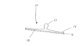
Fig. 1 is a side view of an exemplary electrode in accordance with a first
embodiment of the invention;

Fig. 2 is top view of the electrode shown in Fig. l;

Figs. 3A through 3F illustrate grooved patterns that may be formed on the
bottom of the electrode shown in Fig. 1;
Fig. 4 is a side view of an exemplary electrode in accordance with a second
embodiment of the invention;

Fig. 5 is a top view of the electrode shown in Fig. 4;
Fig. 6 is a side view of a variation of the electrode stud shown in Figs 1 and 4;
and

Fig. 7 is a side view of an exemplary electrode in accordance with a third
2 5 embodiment of the invention.

DETAILED DESCRIPTION OF THE INVENTION

3 0 Fig. 1 shows the conductive electrode 10 according to a first embodiment of
the invention. The electrode 10 includes a stud 12 integral with a body 14. The stud
12 and the body 14 are integrally formed in a molding process using conductive

GCC-2330 -5- 21 93785

plastic. A lead wire with a conventional snap ~tt~chment (not shown) may be
connected to the stud 12. The portion ofthe body 14 away from the stud 12 is thin
and pliable, allowing the electrode 10 to conform to the contours of a patient. The flat
face 18 ofthe electrode 10 is coated with a conductive adhesive 16. The conductive
adhesive 16 may be a pressure-sensitive adhesive or a conductive, adhesive gel. The
conductive adhesive 16 ~tt~ches the electrode 10 to the patient and conducts electrical
signals to and from the patient.

Fig. 2 is a top view ofthe electrode shown in Fig. 1. The electrode body 14
has a large area so that the conductivity of the electrode 10 is significantly greater than
that available with eyelets alone. The dimension of the electrode body 14 is
significantly greater than the dimension of stud 12. In an exemplary~e6mbodimen~t, st~} l /5/
12 has a diameter of 3.92 millimeters and body 14 has a diameter of ~ millimeters.
This feature ~limin~t~s, in part, the need for a silver/silver chloride coating on the
electrode 10. The electrode body 14 may be a variety of shapes such as oval,
. - rect~n~ r~ square, or triangular as well as circular.

As shown in Figs. 3A and 3B, to further enhance conductivity, the flat face 18
of the body 14 contains a grooved pattern 30 to increase the surface area of the flat
2 0 face 18 in contact with the conductive adhesive 16 (shown in Fig. 1). Fig. 3A
illustrates a concentric pattern of grooves 30 which may be V-shaped as shown in Fig.
3B or curved as shown in Fig. 3C. Fig. 3D illustrates a checkerboard pattern of
grooves 30 which also may be V-shaped or curved as shown in Figs. 3E and 3F,
respectively. For ease of illustration, Figs 3A-3F show a limited number of spaced
grooves 30 formed on the flat face 18. It is understood that a large number of grooves
30 may be formed in the flat face 18 and that ~(ljaC~nt grooves 30 may be in close
proxi~ y to each other. It is also understood that a variety of groove patterns and
groove profiles may be used to increase the surface area of the flat face 18 in contact
with the conductive adhesive 16.
The electrode 10 shown in Fig. 1 may be made from carbon-filled plastics such
as polyurethane, polyethylene, or acrylonitrile-butadiene-styrene (ABS) copolymer.

GCC-2330 -6- ~1 q3785

The carbon-filled plastic may be radiolucent or non-radiolucent. A variety of molding
processes may be used to m~nllf~rtllre the electrode 10, inclll~ling injection molding,
casting-type molding, thermal forming, and compression molding. For example, in
injection molding the carbon-filled plastic is heated to a fluid state and forced under
pressure through a runner system into a closed mold. The electrode 10 is removedonce the carbon-filled plastic has cooled and solidified. The mold includes ridges that
form a grooved pattern, such as those shown in Figs. 3A through 3F. In this way, the
entire electrode 10 is formed in a single molding step which reduces costs. In
addition, the reduction in the number of parts forming the electrode 10 reduces the
1 0 scrap rate during m~nllfacture.

Fig. 4 illustrates a second embodiment of the present invention. Electrode 20
includes a stud 22 integral with a base 26. The stud 22 and the base 26 are made from
a conductive plastic and formed through a molding process such as injection molding.
1 5 Of course, other molding techniques may be used as discussed above. The base 26 is
- - he~t seaied to a suosira~e 24 which is also made from a conductive piastic. Substrate
24 is similar to the body 14 (shown in Fig. 1) and includes a thin, pliable region away
from the base 26 which allows the electrode 20 to conform to the contours of a
patient. The outer dimension of the substrate 24 is larger than the outer dimension of
2 0 the stud 22 to provide a large surface area in contact with the patient. Substrate 24
has a hole 25 formed therein. The base 26 completely overlaps the hole 25 and forms
a cavity which assists in ret~ining the conductive adhesive 16. The face 28 ofthe
substrate 24 incl~des a grooved pattern, such as those shown in Figs. 3A through 3F.

2 5 Fig. 5 illustrates a top view of the electrode 20 shown in Fig. 4. The substrate
24 may be any shape and is shown in Fig. 5 as rect~n~ r. This allows the shape of
the substrate 24 to be altered without rh~n~in~ the mold for the stud 22 and the base
26. To customize the electrode 20, only a new substrate 24 needs to be formed and
heat sealed to base 26. Thus, the m~nllf~ctllrer can customize the electrode 20 to a
user's needs without incurring large costs.

21 ~3785
GCC-2330 7

Fig. 6 illustrates a variation of the stud 12 shown in Fig. 1 or the stud 22
shown in Fig. 4. The stud 12 or the stud 22 includes a hollow region 62 that provides
for material relie Of course, this variation requires a more complex mold to
m~nllf~cture.


Fig. 7 illustrates a third embodiment of the present invention. The electrode 70includes a weld area 72 integral with a body 74. The weld area 72 and body 74 are
made from conductive plastic and are formed through a molding process such as
injection molding. Of course, other molding techniques may be used as discussed
above. Body 74 is similar to body 14 (shown in Fig. 1) and in~ des a thin, pliable
region away from weld area 72 which allows the electrode 70 to conform to the
contours of a patient. The face 78 of the body 74 includes a grooved pattern, such as
those shown in Figs. 3A through 3F. The weld area 72 receives a lead wire 76 which
is made of copper or carbon strands. The lead wire 76 is ultrasonically welded to weld
area 72. A conductive adhesive 16 is applied to the bottom of the face 78 to attach
the electrode 70 to the patient's skin and condlict electri~al signals to and from the
patient.

It will be understood by one skilled in the art that many variations of the
2 0 embodiments described herein are contemplated. Although the invention has been
described in terms of exemplary embo~im~nts, it is contemplated that it may be
practiced as outlined above with modifications within the spirit and scope of the
appended claims.

Representative Drawing
A single figure which represents the drawing illustrating the invention.
Administrative Status

For a clearer understanding of the status of the application/patent presented on this page, the site Disclaimer , as well as the definitions for Patent , Administrative Status , Maintenance Fee  and Payment History  should be consulted.

Administrative Status

Title Date
Forecasted Issue Date Unavailable
(22) Filed 1996-12-23
(41) Open to Public Inspection 1997-07-25
Dead Application 2000-12-27

Abandonment History

Abandonment Date Reason Reinstatement Date
1999-12-23 FAILURE TO PAY APPLICATION MAINTENANCE FEE

Payment History

Fee Type Anniversary Year Due Date Amount Paid Paid Date
Application Fee $0.00 1996-12-23
Registration of a document - section 124 $100.00 1997-05-23
Maintenance Fee - Application - New Act 2 1998-12-23 $100.00 1998-12-17
Owners on Record

Note: Records showing the ownership history in alphabetical order.

Current Owners on Record
GRAPHIC CONTROLS CORPORATION
Past Owners on Record
GUSAKOV, IGNATY
Past Owners that do not appear in the "Owners on Record" listing will appear in other documentation within the application.
Documents

To view selected files, please enter reCAPTCHA code :


To view images, click a link in the Document Description column. To download the documents, select one or more checkboxes in the first column and then click the "Download Selected in PDF format (Zip Archive)" or the "Download Selected as Single PDF" button.

List of published and non-published patent-specific documents on the CPD .

If you have any difficulty accessing content, you can call the Client Service Centre at 1-866-997-1936 or send them an e-mail at CIPO Client Service Centre.


Document
Description 
Date
(yyyy-mm-dd) 
Number of pages   Size of Image (KB) 
Cover Page 1998-08-07 1 59
Representative Drawing 1997-08-13 1 2
Office Letter 1997-02-04 2 80
PCT Correspondence 1997-04-24 6 116
PCT Correspondence 1997-05-23 1 39
Cover Page 1997-08-13 1 59
Cover Page 1997-04-23 1 15
Abstract 1997-04-23 1 29
Description 1997-04-23 6 250
Claims 1997-04-23 4 129
Drawings 1997-04-23 7 51