Note: Descriptions are shown in the official language in which they were submitted.
21 93790
.
PROJECTING IMAGES
The invention relates to projecting images.
Referring to Figure 1, light projectors are used,
for example, to display images on large surfaces, such as
movie or television screens. In a front projection
system 20, an image beam 24 is projected from an image
source 21 onto the "front" side of a reflection-type
10 angle transforming screen, which then reflects the light
toward a viewer 27 positioned in front of the screen. In
a rear projection system, the image beam is projected
onto the "rear" side of a transmission-type angle
transforming screen 26 and transmitted toward a viewer 29
15 located in front of the screen.
Due to the physical properties of light, the size
of the image beam 24 when it reaches the screen 26
depends upon the magnification rate of the image source
21 and the distance between the screen 26 and the image
20 source 22. To efficiently utilize the screen 26, the
image beam 24 should just fill the entire height S and
width (not shown) of the screen 26. In Figure 1, the
image beam 24 fills the screen 26 when the source 22 is
at an appropriate distance D from the screen 26, i.e.,
2! 93790
when the center of the image beam 24 follows an optical
path 28 of length D. The optical path length D depends
upon the screen height S and the magnification rate of
the image source. Any non-transparent object placed in
5 the path of the image beam 24 typically will obstruct the
image beam 24 and form a shadow on the screen 26.
Referring to Figure 2, designers have reduced the
size of the typical image projection system 30 by
"folding" the optical path of the projected image beam to
o reduce the apparent projection length L of the system 30.
The "folded" system 30 includes one or more mirrors 34,
36 placed at strategic points along the optical path to
redirect the projected image and to form multiple optical
subpaths Dl, D2, D3. The overall system configuration in
15 this optical system 30 is more rectilinear than the
conical system configuration of Figure 1.
In the folded image projection system 30,
assuming that the image source 40 and the screen 32 are
similar to those in Figure 1, the image 38 fills the
20 screen 32 entirely when the mirrors 34, 36 are positioned
such that the combined length of the optical subpaths Dl,
D2, and D3 equals the optical path length D in Figure 1,
even though the apparent projection length L is less than
- D.
An "extra-folded" projection display system
includes a selectively reflective material (e.g., a
linear reflecting polarizer) placed immediately behind
the system's imaging screen. The display system includes
30 an image projector that projects an image beam containing
light of a predetermined linear polarization toward the
imaging screen. The linear reflecting polarizer reflects
the light in the image beam away from the screen. The
reflected image beam then encounters a l/4-wavelength
35 achromatic retarder which converts the linear
polarization to circular polarization. The image beam
2 1 93790
next hits a mirror that reflects the light back through
the 1/4-wavelength achromatic retarder, which converts
the circular polarization back to linear polarization,
with the polarization director rotated 90~ from the
5 original polarization director. The linear reflecting
polarizer then allows the light to pass through to the
image screen.
Embodiments of the invention may include the
following features. The system may include a powered
0 optical element to further increase the "folding" of the
image beam, change the magnification rate, provide
distortion correction, or optimize packaging. The image
beam may be folded even further by allowing it to reflect
from the mirror twice and to pass through the achromatic
5 retarder four times. The mirror may be positioned
between the image source and the imaging screen.
Advantages of the invention may include one or
more of the following. An optical element placed
immediately behind the screen in a projection imaging
20 system may act as a "mirror" that increases the amount of
folding that the light undergoes and therefore may reduce
the apparent projection length, or depth, of the system
to a greater extent than previously possible. The image
source may be placed behind all optical elements in the
25 display system, further reducing the size of the system.
Other advantages and features will become
apparent from the following description and from the
claims.
Figure 1 is a side view of a prior art projection
display system.
Figure 2 is a side view of a prior art folded
projection display system.
Figures 3, 4, and 5 are side views of an "extra-
35 folded" projection display system.
Figures 6A and 6B are "patchwork" polarizers that
21 93;790
.
may be used in the system of Figures 3, 4, and 5.
Figures 7A, 7B, and 7C are specialized achromatic
retarders that may be used in the system of Figures 3, 4,
and 5.
Figures 8, 9, and 10 are side views of
alternative "extra-folded" projection video systems.
Figures llA and llB are side and front views of a
configuration of multiple projection video systems of
Figure 8.
o Figures 12A and 12B are side and front views of a
configuration of multiple projection video systems of
Figure 9.
Figures 13, 14A, and 14B are side views of
alternative "extra-folded" projection video systems with
powered optical devices.
Figure 15 is a computer system having an "extra-
folded" projection video display.
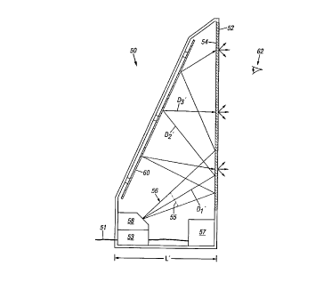
Referring to Figure 3, an "extra-folded"
20 projection video system 50, such as a projection
television, includes a diffusive screen 52 having a
surface 54 that is covered by a selectively reflective or
transmissive material. The selectively reflective or
transmissive surface 54 allows the screen 52 to act at
25 times as a mirror and at times as a transmissive imaging
screen. As a result, an image 55 contained in an image
beam 56 projected by an image projector 58 reflects from
the rear surface 54 of the screen the first time it
encounters the surface 54. The image beam 56 then
30 travels toward a mirror 60 located behind the screen 52,
which in turn reflects the light 56 back toward the
screen 52. When the image 55 in the image beam 56
encounters the rear surface 54 of the screen 52 the
second time, the image 55 passes through the screen 52
35 toward the viewer 62.
In this manner, the screen 52 essentially acts as
2 1 931790
a "mirror" placed directly between the viewer 62 and the
rear mirror 60. The screen 52 reflects the image beam 56
away from the viewer but does not block the image beam 56
or significantly deteriorate the quality of the image 55
5 seen by the viewer. Because a "mirror" is placed at a
position along the optical path that previously had to be
free from such objects, the image beam 56 projected from
the image source 58 is "extra-folded", i.e., folded more
often and over a much smaller linear distance L' than is
lo possible with existing systems.
The projection system 50 receives an electronic
signal through an input cable 51 and provides it to a
signal splitter 53. The signal splitter 53 divides the
electronic signal into a video signal and an audio signal
5 and provides these signals to the image source 58 and a
sound system 57, respectively. The image source 58
converts the video signal into light and projects the
light as an image beam 56. The image source 58 may be
any type of image projection engine, such as a liquid
20 crystal display ("LCD") projector. The electronic signal
may be any type of signal containing video information,
such as a television signal received by an antenna or
over cable lines or a computer video signal received
through a computer video cable. The audio signal and the
25 sound system 57 are optional.
Referring also to Figure 4, the screen 52 is able
to act as a mirror at some times and as an imaging screen
at other times because its rear surface 54 is covered by
a linear reflecting polarizing material, such as
30 Minnesota Mining & Manufacturing Company's double
brightness enhancement film (DBEF) material. The linear
reflecting polarizing material forms a polarizer 64 that
transmits substantially all light linearly polarized in
one direction (the "direction of transmission") and
35 reflects substantially all light linearly polarized in a
direction orthogonal to the direction of transmission.
21 93790
.
For example, if the linear reflecting polarizer 64 is
oriented to transmit p-polarized light, it reflects
substantially all s-polarized light because s-polarized
light is orthogonal to the polarizer's direction of
s greatest transmissive efficiency. Conversely, when p-
polarized light encounters the polarizer 64,
substantially all of the light passes through the
polarizer 64 and the diffusive screen 52 toward the
viewer because the p-polarized light is aligned in the
o direction of the polarizer's greatest transmission
efficiency.
The linear reflecting polarizer should have a
transmission efficiency of at least 99%, so that less
than 1% of s-polarized light escapes the projection
5 system and all but 1% of p-polarized light is projected
to the viewer. A linear absorption polarizer 68 may be
used to further filter improperly polarized light from
the image beam. Both the reflecting polarizer 64 and the
absorption polarizer 68 may be attached to the screen 52
(e.g., by an index matching glue) or may be suspended in
the display system (e.g., by a one or more frames
connected to the system's housing).
Referring also to Figure 5, the polarization of
the light traveling between the image source 58 and the
25 imaging screen 52 is altered by a 1/4-wavelength
achromatic retarder 70 positioned between the imaging
screen 52 and the rear mirror 60. The retarder 70 may be
attached to the front surface of the mirror 60 or
suspended in the system by other means.
The 1/4-wavelength achromatic retarder 70
comprises a material that delays one linear component of
a light wave passing through it by 1/4-wavelength. Such
a material is produced by Nitto Denko Corporation of
Japan under the name WB-1/4, and similar materials are
35 available from other sources. Therefore, the retarder 70
transforms linearly polarized light into circularly
21 93790
polarized light and transforms circularly polarized light
into linearly polarized light. Furthermore, light that
twice passes through the retarder 70 has the same linear
component delayed twice, or by 1/2-wavelength. So
5 linearly polarized light passing through the retarder 70
two times emerges with a polarization orthogonal to that
at which it began.
For example, s-polarized light 72 travelling
along optical sub-path D2' is transformed into circularly
lo polarized light 74 when it passes through the achromatic
retarder 70. After reflecting from the second mirror 60,
the circularly polarized light 74 becomes p-polarized
light 76 when it passes through the retarder 70 again.
The p-polarized light 76 then travels along optical sub-
5 path D3' and eventually passes through the linearreflecting polarizer 64 and onto the diffusive imaging
screen 52.
Referring also to Figures 6A and 6B, the "extra-
folded" projection system can include a "patchwork"
20 polarizer 90 or 92 that compensates for trapezoidal
distortions occurring when the image is reflected in the
system. The linear reflecting polarizing material 64 may
be slightly sensitive as to the incoming angle of the
light. That is, the polarization of the reflected light
2s may not be perfectly s-polarized but may be slightly
circular. The patchwork polarizer 90 or 92 compensates
for this potential condition. The patchwork polarizer 90
or 92 may be located anywhere between the image source 58
and the last reflective element in the system.
The "patchwork" polarizer 90 of Figure 6A may be
placed within the image source 58 (Figure 3), such as on
the surface of the lens that typically forms the last
stage of an LCD projector. The substantially circular
polarizer 90 is a linear absorption polarizer having
35 several regions 90a-9Of with different transmissive
properties. Each pair of adjacent regions is divided by
21 93790
, ~_
a linear boundary 91a-9le extending through the polarizer
90. The polarizer 92 of Figure 6B may be placed on one
of the reflective surfaces in the display system and
preferably is incorporated into the DBEF material of the
5 linear reflecting polarizer 64 (Figure 4) on the system's
display screen 52. The transmissive properties, size,
and shape of each region in the patchwork polarizer 90 or
92 are determined by the structure of the display system
and, in particular, by the trapezoidal distortions
lo imparted by the system.
Referring to Figures 7A, 7B, and 7C, the
achromatic retarder 70 can be constructed to accommodate
the varying angles of incidence at which light from the
image source 58 impinges upon the retarder 70. If the
5 image source is located below the page and toward the
reader, light from the image source will hit the page at
higher angles of incidence on the lower half of the page
and at lower angles of incidence on the upper half of the
page. Likewise, if the image source is positioned below
20 the center of the page, light from the source will hit
the page at higher angles of incidence on the center of
the page and at lower angles of incidence on the left and
right edges of the page. Because the retarder's effect
on a particular light ray may depend upon the angle of
25 incidence at which the light ray strikes the retarder,
the retarder 70 can consist of several regions having
different retardation properties.
As shown in Figure 7A, the retarder 70 may be
divided into two regions 69a, 69b having two different
30 retardation values ~1 and ~2. Region 69a accommodates
light passing through the retarder 70 at lower angles of
incidence, and region 69b accommodates light passing
through at the higher angles of incidence. Referring to
Figure 7B, the retarder instead may be divided into a
35 linear grid having, e.g., two retardation values ~1 and
~2 along a vertical axis ~ and three retardation values
2 1 93790
2~ and ~3 along a horizontal axis ~. The retarder 70
then is divided into six sections 71a-71b, the
retardation value for each of which is determined by the
corresponding vertical value ~1 or ~2 and the
5 corresponding horizontal value ~ 2~ or ~3.
Alternatively, as shown in Figure 7C, the retarder 70 may
be divided into several substantially circular or
elliptical regions 73a-73h intersecting at the center
point 75 of the retarder's bottom edge 77. The innermost
o region 73a accommodates light passing through the
retarder 70 at the highest angles of incidence and the
outermost region 73h accommodates light passing through
the retarder 70 at the lowest angles of incidence. A
retarder manufacturer (e.g., Nitto Denko Corporation of
5 Japan) can create an appropriate retarder given the
structure and dimensions of the projection display
system.
Referring to Figures 8 and 9, the "extra-folded"
projection display system 50 may be constructed with
20 various spacial configurations. In the system of Figure
8, the image source 58 projects an image beam directly
onto the linear reflecting polarizer 64, which first
reflects the image beam toward the achromatic retarder 70
and then allows the reflected image beam to pass to the
2s imaging screen 52. In the system of Figure 9, the image
source 58 is located behind the mirror 60. The image
source 58 projects an image beam downward onto a smaller
mirror 100 that in turn reflects the image beam toward
the linear reflecting polarizer 64. The linear
30 reflecting polarizer 64 then reflects the image beam
toward the achromatic retarder 70 and the rear mirror 60,
and then allows the reflected p-polarized light to pass
to the display surface 52.
Referring to Figure 10, the "extra folded"
35 projection display system 50 may be folded even further
by allowing the image beam to reflect (or "bounce") from
21 93790
.
the rear mirror 60 twice, instead of the single bounce
shown in Figure 3. In this embodiment, the image source
58 projects p-polarized light directly toward the rear
mirror 60. After reflecting from the mirror 60 and
5 passing through the achromatic retarder twice, the light
in the image beam 56 has s-polarization. The s-polarized
light then reflects from the linear reflecting polarizer
on the screen 52 back toward the rear mirror 60. Another
reflection from the mirror 60 and two additional passes
lo through the achromatic retarder direct the image beam,
which again contains p-polarized light, back toward the
screen 52, where the light passes through the linear
reflecting polarizer to form images on the imaging screen
52.
Figure llA is a side view of an arrangement of
multiple units of the projection display system 50 of
Figure 8. Each unit 250a, 250b includes an outer housing
200. The housing 200 mounts the screen 52, the mirror
60, and the image projector 58 in the proper positions.
20 The bottom front surface 202 of the housing 200 is
recessed below the screen 52 to allow stacking, as shown
in Figure llA, so that the screens 52 of the units 250a,
250b are substantially coplanar. A support 204 mounted
on the back surface of the lower unit 250b holds the
25 upper unit 250a in place. Referring to Figure llB, the
front view of the arrangement is shown. As can be seen,
the screen 52 is approximately the width of the unit
250a, so that there is very little border. As a result,
a plurality of units 250a-250d can be arranged in an
30 array or "tiled" configuration with very little gap
between individual units.
Figure 12A is a side view of an arrangement of
multiple units of the projection display system 50 of
Figure 9. Each unit 260a, 260b includes an outer housing
35 210. In this instance, the outer housing is
substantially a rectangular parallelepiped, unlike the
2 1 93790
.
11
recessed and angled shape of housing 200 in Figure llA.
However, the imaging screen 52 goes to substantially the
edge of the housing 210 on all four sides, without a
recessed surface 202 as in housing 200 (Figures llA and
5 llB). Figure 12B is the front view of the arrangement of
Figure 12A. The design of Figure 9 thus has trade offs
with the design of Figure 8 relating to depth and base
dimensions, with the final use affecting the choice of
designs.
lo Referring to Figure 13, in another alternative
embodiment, the image source 58 is placed behind the rear
mirror 60 near the top of the projection system. In this
arrangement, the image source 58 projects the image beam
upward onto a small mirror 102 at the top of the
5 projection system. The small mirror 102 in turn reflects
the image beam downward and onto a larger mirror 104
located at the bottom of the projection system. To
prevent the image beam from diverging too rapidly between
the image source 58 and the lower mirror 104, the image
20 source 58 projects the image beam with only slight
divergence (or magnification). As a result, the lower
mirror 104 is a "powered" optical device that magnifies
the image beam as it reflects the beam toward the linear
reflecting polarizer 64. The lower mirror 104 magnifies
25 the image beam enough to fill the entire surface of the
imaging screen after reflecting once from the linear
reflecting polarizer 64 and once from the rear mirror 60.
The upper mirror 102 also may be a "powered" optical
device, as shown in Figure 14A. Alternatively, the upper
30 mirror may be a "negatively powered" optical device that
causes the image beam to converge until it reaches the
lower mirror 104, as shown in Figure 14B.
Referring to Figure 15, an "extra-folded" image
projection system may be incorporated into a computer
35 display 106 small enough for use with a desktop computer
108. Like conventional CRT or LCD panel displays, the
2 1 93i790
12
projection display subsystem 106 may be driven by a
conventional CPU 112 and video controller 113 that
provide video data to the projection display subsystem
106 through a standard video cable 114. Because the
5 screen 116 is used as a "mirror" to "fold" the video
image into a very small area, the projection display
subsystem 106 combines the benefits of flat screen
technology and projection video yet requires only a small
area on the desktop.
0 Other embodiments are within the scope of the
following claims. For example, the video projection
system may be incorporated into many types of video
display systems, such as small and large screen
televisions, laptop and desktop computers, overhead
15 projectors, movie theaters, and holographic imaging
systems.