Note: Descriptions are shown in the official language in which they were submitted.
21 ~~ 4-0~ 1 1
English translation of the application text as originally filed
AN APPARATUS AND PROCESS FOR PRODUCING A CORRUGATED WEB AND AN
ABSORBENT ARTICLE COMPRISING A CORRUGATED WEB
Description
The invention relates to an apparatus and process for
continuously producing a web from a thin sheet material which
is corrugated at least in partial sections thereof and elastic
at least in transverse direction. Moreover, the invention
relates to an absorbent product comprising a corrugated web.
From examined German patent application DE 2011802 B2 laid open
for public inspection an apparatus is known which deals with
the corrugation of a paper web. Due to the material properties
of the paper to be processed, the shape of the guide bed of the
known apparatus must be geometrically very complex and
physically curved, which requires a high expenditure in
production engineering and is thus disadvantageous.
From German patent DE 2945395 C2 a forming plate for a folding
device of a cording machine is known consisting of a base plate
and a plurality of folding ribs on the surface thereof , which
ribs comprise parallel extending portions projecting beyond one
edge of the base plate and portions extending radially or fan-
shaped on the base plate. The folding ribs are separate blades
which are releasably attached to the base plate and disposed in
grooves formed in the base plate, each of which exhibits in a
partial section a recess into which holding brackets engage
which project from the lower edge of the blades. The known
device does not enable a stabilization of corrugations. The
corrugations formed are much rather pressed flat and fixed by
sewing in a tube shape on the initial web.
P'tTEX'I"~P?,TEV i'.o5S9PC:~e DOC
CA 02194011 2005-02-28
2
A further device for forming longitudinal folds in a
continuous web is described in German patent DE 3611134 C2.
In this device, a very elastic paper which can be made
almost plastically deformable by moistening, e.g., for
cigarette filters, is slowly drawn into carrugations from
the center outwards between a large number of nested combing
rollers. The embodiment shown of this very complex machine
is only intended for forming corrugations in sections.
Corrugations cannot be produced over the whole web due to
the constant alternate web curvature.
Finally, German patent DE 2827495 C2 describes a device for
transporting and combining a web of material in which the
main aspect of the invention is the transportation of the
web and simultaneous funnel-shaped tapering using a flow of
air. It is not possible to obtain an exact corrugation of
the folds with the known device.
The present invention is thus based on the object of
providing an apparatus and a process for producing a
corrugated web and an absorbent article which avoids the
drawbacks of the prior art.
The apparatus of the invention comprises a guide bed into
which fan-shaped grooves are cut, the depth of said grooves
increasing preferably linearly to produce a corrugated
cross-section of the desired dimension, into which holding-
down devices dip from the opposite side according to the
available
3
219()11
height. The corrugated webs produced by means of the apparatus
of the invention may have the same corrugation height over the
~antire web width or different corrugation heights i.f the guide
',red is configured accordingly. It is self-evident to the person
;skilled in the art that the guide bed may also comprise one
groove only if the desired corrugated we:b shall exhibit
corresponding properties. In this case, only one holding-down
device is required as well. The holding-down devices are
preferably rod-shaped and preferably freely shiftable
perpendicular to the guide bed at the end facing the inlet end
of the guide bed as well. as at the end facing the outlet end of
i:he guide bed. The holding-down devices can be supported at
both ends or may have one free unguided or unsupported end_ It
_~s advantageous for the holding-down devices to be of certain
elasticity. Spring steel is a suitable material for the
holding-down devices. The holding-down devices may be guided in
at least one guide face extending perpendicular to the guide
k>ed. If, in addition, the holding-down devices press the web
against the guide bed through force-exerting means with a
predetermined load, this will permit a certain adjusting effect
f=or the continuos web which compensates for differences in
tension in the material due to the formation of the folds not
always being geometrically accurate. The predetermined force
exerted on the holding-down devices can also be applied by a
biasing of the holding-down devices. This renders additional
force-exerting elements superfluous. Besides a round cross-
section of the holding'-down devices, which is particularly
preferred, the holding-down devices may also have a triangular,
rectangular, semicircular or trapzoidal cross-section.
Lt is of particular advantage for the free ends of the holding-
a.own devices to be bent substantially parallel to each other or
provided with corresponding shoulders which are received in
bores of at least one guide element positioned at the end face.
Furthermore, with respect to the direction of movement of the
f' ~'tLJCT'P.4TEVT ti589PC 11S~' DOC
4
219401 1
web, it is advantageous for all holding-down devices to be
received forward and rearward, respectively, of the surface
portion of the guide bed which comprises the grooves.
F>referably, the holding-down devices are of round cross-
~section. The diameter may be, for example, from 0.:1 to 5 mm,
preferably 1 to 3 mm, in particular 2 mm. The distance between
the grooves may be, for example, from 1 to 5 10 mm, preferably
2. to 4 mm.
~'he force-exerting means may, for example be a pressure plate
which acts between the ends of the holding-down devices on
same. The pressure plate, may additionally be provided with at
least one spring member. Weights, compressed air, vacuum or
magnets may also be used to exert a force. If magnets are used,
permanent magnets as well as electromagnets are suitable which
should be provided on the side of the guide bed opposite to the
web to be formed. It is self-evident to the person skilled in
the art that, when use is made of a magnet, the holding-down
devices or an element acting on the holding-down devices, e.g.,
a contacting pressure plate, should exhibit ferromagnetic
properties.
The corrugated webs of thin material produced by means of the
apparatus of the invention or the process of the invention must
be fixed after leaving the guide bed in order for the
corrugations to remain permanently. One possibility to fix the
corrugated web is to join it with a web material (backing web)
or several web materials (backing webs). i~.nother fixation
possibility is to plastically deform the corrugated web
permanently between stamping rollers. Furthermore, it is
possible to fix the corrugation of the corrugated web in that a
hardening agent is sprayed on. If a backing web is used to
stabilize the corrugated web, the webs are preferably joined by
a bonding agent, such as an adhesive. The joining, however, can
also be effected by thermal treatment or ultra~~onic welding.
PvTL:7CTP;T.':i ti~S9PCIl~;'DOC
5
2194011
~~ccording to a further embodiment, the guide-bed is provided,
seen in cross-section, with different corrugation heights, the
maximum corrugation height being usually formed in the center,
the corrugation height decreasing towards the edges of the
guide bed.
Furthermore, it is advantageous for the guide bed to be
provided, seen transversely of the direction of movement of the
material web, such that not all grooves start at the same
height . It is particularly preferred for the grooves to start
in the central portion of the guide bed, with grooves starting
further downstream being arranged in the peripheral portions.
Furthermore, it is desirable in certain embodiments for the
guide bed to be so arranged as to be not provided with grooves
over the entire width such that no grooves area provided in the
central portion and/or the peripheral portions of the guide
bed.
Finally, the apparatus of the invention may comprise a device
with meshing rollers for stamping the produced corrugated web,
said device with meshing rollers being provided downstream of
the guide bed.
The corrugated web produced with the process of the invention
and the apparatus of the invention can advantageously be used
as component of an absorbent article for absorbing body fluids,
such as a diaper, sanitary napkin or incontinence pads. Such an
absorbent article usually comprises a liquid-impermeable cover
sheet disposed away from the body in use, a liquid-permeable
cover sheet disposed towards the body in use and an absorbent
body disposed between said liquid-permeable and said liquid-
iwpermeable cover sheet. The absorbent article of the invention
is distinguished in that the liquid-permeable cover sheet
P ',TE?CT °:~Tc'.~'T6p89PC1 W DOC
X194(:)11
<~nd/or the absorbent body comprises at least in partial
:sections thereof corrug<~tions ( "pleatings") . 'To this end, webs
<~an be used which have been laid in folds by means of the
~~rocess of the invention or the apparatus c>f the invention.
'The webs produced according to the invention are advantageous
as compared to corrugated webs conventionally produced by means
of stamping rollers in that they are of superior wearing
<~omfort and improved absorbing capacity, because t:he treated
material is practically not compacted in the forming process.
'Che invention is described in more detail below with reference
t=o the attached drawings, wherein:
Fig. 1 is a perspective, partly cut-open view of a machine
for producing a corrugated web from highly elastic
material which is bonded to a backing web;
Fig. 2 is a perspective plan view of the corrugated web
which also represents the shape of the guide bed in
a preferred embodiment;
Fig. 3 is a perspective view of an alternative corrugation
configuration starting in the centre;
Fig. 4 is a perspective plan view of a web or guide bed
with partial corrugations only;
Fig. S is a cross-section through three sections of the
guide bed at. the beginning, in the centre and at
the end with a schematic representation of the
drawn-in web;
Fig. 6 shows different theoretically possible shapes of
the corrugated web with different draw-in factors;
P \TE?C~PATFW'o5S9PCI W UOC
~~ 940 ~
F'ig. 7 represents material-technical considerations for
webs to be preferably processed;
F'ig. B is a side view of the guide bed end with a bonding
device as well as the fixation of a pressing means
for the holding-down devices by means of pneumatic
cylinders and knee lever;
Fig. 9 is a partially cut-open perspective view of the
guide bed and the holding-down devices to which
variable forces can be applied sectionwise by means
of separately activatable electrom,agnets,;
Fig. 10 is a view of the two rollers of the bonding station
with the holding-down devices engaging into the
corrugated roller and the application of adhesive
in lines;
Fig. 11 is a schematic view of stamping rollers disposed
after the guide bed which deform the corrugated web
at the corrugation peaks by pressing for the
purpose of fixation;
Fig. 12 is a schematic view showing the application of a
second web with the following pressing station for
fixing the adhesive bond;
Fig. 13 is a schematic view of a further preferred
embodiment for bonding the second web, and
Figs. 14 to 21 are schematic views of ab:aorbent articles
according to the invention.
F~ccording to Fig. 1, t:he web 1 to be corrugated enters the
corrugating device at the front edge 3 of they guide bed 2, is
P \TEXi u'ATEIT os89PC1 W.DOC
8 ~194~11
pressed into the guide bed by the rod-shaped holding-down
devices 5 and leaves the guide bed in corrugated form at the
outlet end 4. The holding-down devices are held :in a front
spacer 8 and a back spacer 9 so as to keep them at a constant
distance apart from one another, and in the embodiment of Fig.
1. they are pressed down with a defined force by means of a
spring-loaded pressure plate l0 adjustable via set screws 11.
The holding-down device: are supported to be freely shiftable
i.n the direction of the guide bed.
The corrugated web is joined with the backing web 6 directly
after leaving the guide path 2 which is effected by means of a
~~mooth roller 13 and a roller 12 with profi~_ed cross-section
a.s shown in the view of Fig. 10. The pressure force required
for the subsequent bonding of the sheets is provided here by
means of two pneumatic cylinders via levers.
In order to join the backing web with the corrugated web, a
solution is shown here in which use is mad= of an adhesive
applied in lines 16 by means of a multiple nozzle 15 for
adhesive application. Due to the specific shape and attachment
c>f the rod-shaped holding-down devices, the ends of which
extend into the profiled roller 12, as is also evident from
F'ig. 10, the corrugations formed in the web are prevented from
~~pringing back prior to bonding.
The corrugated web 3 in Fig. 2 corresponds e:~sentially to the
planar guide bed. A linear increase in the corrugations is
evident which permits simple manufacture of the forming device.
To reduce local tensiors in a less elastic material, it is
advantageous for the guide bed to be formed as Shawn in Fig.
with the corrugation formation starting in the centre of the
web and being gradually followed by corrugations further
towards the edge. However, in such a configuration the
installation of the holding-down devices involves an increased
P:'~TE~TYATE:~T 6p&9PC 1 W DOC
2194011
=_xpenditure in production engineering, since they must form the
full corrugation height over paths of different length and have
~~ifferent inclinations relative to the guide f>ed.
for webs which, according to the invention, are not to be
~~orrugated over the entire width, the shape of the guide bed
may be as shown in Fig. 4 with only a few corrugations with
;planar guide bed sections 19 therebetween. In the extreme case,
the guide bed may comprise one groove only, as already
mentioned above.
'rhe configuration of the guide bed and the holding-down devices
.pan result into a draw--in behaviour which is not uniform over
the entire length of the corrugation formation. path as is shown
schematically in Fig. 5. By means of a calculation program, the
draw-in factor can be determined and optimizE:d for the web to
be corrugated at any point of the guide bed. According to the
solution provided by the invention, the ideal value is achieved
,s.t the beginning of the corrugation configuration, <~s shown in
and at the end, as shown in c, whereas only about 920 of the
material is drawn-in at the centre of the guide bed, as shown
in b, which is, however, compensated for by the elasticity and
low flexural strength of the web.
:Depending on the intended use, most various corrugation shapes
can be theoretically produced as is shown in Fig. 6. However,
the cornered corrugations according to a and b would require a
chemical and physical treatment, for example, by spraying with
a hardening agent, thermal hardening or strong plastic
deformation by stamping, in order to maintain the cross-section
shown. The draw-in values differ between 1.4~~ for 45°
triangular corrugations and 1.32 for the trapezoidal shape with
1/3 straight section and a value 2 at 60° inclination of the
corrugation or 1.66 for the trapezoid.
P \TEXTIPATE?~ : 6;S9PC:SV DOC
10
219401 1
For the preferred embodiment c with semi-circles and straight
sections of more or less length, the material draw-in is
between 1.45 for short straight sections with 50° inclination
and values of more than 2 for almost perpendicular straight
sections. The two contiguous semi-circles a_re a special case.
The draw-in factor in this case is exactly n/2, i.e., 1.57.
This corrugation shape is also advantageous as far as the
balance of internal tensions and the stability to external
forces is concerned, without additional stabilizing measures
being applied. When being bonded to a backing web, the
corrugations will be automatically flattened to a certain
extent -- depending on the bonding process -- so that the
actually produced corrugation cross-section assumes the shape
d.
In order to be capable of being passed through the apparatus of
the invention, the web to be processed should have certain
physical properties: low flexural strength rigidity and high
elasticity. These requirements are, for example, fulfilled by
low-density fibrous materials and plastic foils. Fi.g. 7 shows a
stress-strain curve far different materials. In contrast to
paper, which requires little deformability and high strength in
production, such materials exhibit a certain, deformability and
a yield limit which is mostly not defined exactly and high
breaking elongation. E~referably, the proce;ased material webs
are elastic at least in transverse direction.
For the formation of corrugations, the web is calculated to
require at the end of the forming process a distance in
transverse direction approximately 8%~ greater than in the
middle of the process, which every material examined so far
withstood without problems, because this results at best into a
minimal permanent deformation which is not even undesired in
the present case of the application. Accordingly, the machine
with a guide bed of simple design for producing corrugations in
o , TEXT PATE \T,6p 89PC 1 W DOC
X19-4011
thin webs is in particular suited for all materials which can
bear about 10% elongation or more without breaking. Although
i:.here is no upper limit for the elongation, materials are
preferred which allow an elongation of 10 to 150%.
'Che following Table 1 shows a few examples of materials or
material combinations which can be processed with the apparatus
of the invention and by means of the process of the invention
=or producing corrugated webs. The webs produced are also
referred to as "pleated" webs and, accordingly, the material
used for this purpose is also referred to as "pleatable"
cnaterial.
P \TEX'PP.4TE1T~6589PC I W bOC
12
~1 g~~1 1
Table 1
lflaterials DimensionsCard Spun- Laminate: Laminate:
nonwoven bonded '~-and Spun-
nonwoven/ bonded/
nonwovenperforatedperforated
foil foil
basis weight g/m~ 18 16 ~l3 4'
Thickness mm 0.18 0.13 0.92 0.50
Strength, dry
longitudinal N/50 mm 40 30 55 13
transverse N/50 mm 18 20 19 6
elongation,
dry
longitudinal % 50 50 35 344
transverse % 90 60 150 78
friction, dry
Inner side ~.D 0.65 0.33 0.41 0.30
(foil)
Outer side ~.D ~ 0.65 ~ 0.33 (1.41 0.93
~ ~
i nonwoven)
I:n order to provide uniform corrugation configuration with the
apparatus of the invention it is advantageous that a defined
force acts on the web which is exerted by the holding-down
devices. This may be accomplished by means o:E weights, spring
force (see Fig. 1) or also adjustable during operation by means
of pneumatic or hydraulic cylinders 20 in accordance with Fig.
E., a pneumatic cylinder being preferred due t.o the low forces
required and less leakage. For reasons cf compactness, this
cylinder may be installed longitudinally, for example, and act
c>n the pressing plate 10 via knee levers 21. According to
theoretical examination~~ and practical test rE=_sults, depending
on the material treated. in each case, <~ lin~ea:r load of from
C> . 04 to 0 . 06 Ncm-1 has proved favourable for web speeds of up
°=.TE:CT'P?,TEVT 6589PCI W DOC
13
21901 1
t.o 150 m/min. The total contact force thus reaches about 20 N
at a guide bed length of 300 mm. If the basis weight and/or the
flexural strength of the material is changed, a load of, for
example, 0.01 to 0.1 Ncm-1, preferably 0.02 to 0.08 Ncm-1 is
~;uitable. Apart from the adjustability of the holding-down
forces, the use of pneumatic cylinders is also advantageous in
that the device can be pneumatically lifted and relieved for
entering the web. Web speeds of up to 250 m/m.in are obtainable
with suitable materials.
Fig. 8 is a side view of the holding-down rods 5 which extend
into the profiled roller 12 together with the rearward support
which is adjustable by means of clamping screws.
I:n order to obtain an even more individual force distribution
in the holding-down devices, electromagnets 22 may be
accommodated in the guide bed of the apparatus of the invention
as is shown in the preferred embodiment of Fig. 9, said
electromagnets being activated, as required, either in groups
or individually, the formation of corrugations being thus
influenced with particular sensitivity. T7ze ferromagnetic
holding-down rods 5 are attracted by the electromagnets with up
t:o 0.1 Nmm-2, i.e., with a rod width of 2 mm, either a very low
current or a correspondingly distributed small number of
individual magnets suffices to produce the required contact
pressure. This solution involves the advantage that, regardless
of a possibly different degree of wear of the holding-down
rods, a uniform corrugation formation is nevertheless enabled
without readjustments being required.
I>ue to the instabili~y of the processed material, the
corrugations formed would spring back to the initial planar
c:ondition after leaving the forming apparatus if no additional
measures were applied, e.g., joining with a backing web,
P vTEX C YATE~T'.6589PC 1 W DOC
14
219401 1
thermoplastic modification or fixation by means of a sprayed-on
hardening agent.
If a backing web is used for stabilization, it can be made
from the same material as the corrugated web or of a different
material. The joining with a backing web is preferably
effected, as shown in Figs. 1 and 10, by bonding a planar web 6
with the peaks (maxima and minima) of the corrugated web 1
formed. In this procedure, the corrugations are forcibly held
between a roller 12 provided with grooves, corresponding to the
distance of the holding-down devices 5, and the rod ends of the
holding-down devices, while a roller pressed from above, e.g.,
via the pneumatic cylinders, supplies the second web 6 to which
adhesive 16 is applied in lines in the area of the corrugation
peaks by means of a multiple nozzle.
The joining of the corrugated web with the backing web according
to Fig. 1 by the application of adhesive 16 in lines is only
one of the possibilities suitable for this purpose. The use of
wheel or screen printing devices as adhesive applicators is
conceivable.
As the apparatus of the invention can preferably be used for
the processing of webs of synthetic foils or nonwoven webs, the
corrugated web formed can be welded to the backing web by
introducing thermal energy, e.g., via the corrugated transport
roller 12.
A similar bonding effect is obtained by pressing the webs
together in the valleys of the upper corrugated web, i.e.,
using an ultrasonic press shoe or a press ro7_ler.
To fix the shape of the corrugations also without an additional
backing web, the corrugated web can be plastically deformed at
the peaks 24 of the~corrugations between stamping rollers 23
P ' TE YT,P.4TE VT,6589PC 11~' DOC
15 219 4 ~ 1 ~
having a corrugated cross-section, preferably in accordance
with Fig. 11. This effect can also be obtained or increased by
thermal or chemical-physical action such as spra~~ing with a
hardening agent.
A further advantageaus embodiment of the invention consists in
that, as shown in Fig. 12, the side of the corrugated web
opposite to the backing web 6 is also bonded to a further
material web 25. This material web 25 is also reff~rred to as
cover web. To this end, for example, this web can be fed by a
roller of larger diameter 26 and a belt system 27, with
adhesive being applied :in lines by an application device 15. In
an advantageous embodiment, bonding to the corrugated web 1 can
be achieved by a second belt system 28 and .a pressure device
30, which evenly distributes the contact pressure, the support
29 acting against the contact pressure.
According to Fig. 13, the corrugated web leaving the guide bed
2 is pressed by a corrugated roller 12 against a smooth roller
31 of larger diameter and bonded to the backing web 6, to
which, for example, adhesive has been previously applied in
lines by means of a suitable device 15.
The curvature of the roller 31 is selected such that the
corrugated web is on:Ly slightly elastically deformed and
returns to its original cross-section after leaving the roller.
Adhesive can be applied to the peaks of the corrugations in one
area of the roller 31 using a basically known adhesive device
32. The joint is strengthened by a subsequent pressure section,
as shown in Fig. 12, with a controlled contact pressure being
applied.
Furthermore, the invention relates to an <~bsorbent article
suitable for absorbing body fluids. Such articles are, for
P v IEX'C'PATL\T 653yPC I lL' DOC
211 ~4~ 1 ~
example, articles for feminine care, like sanitary napkins, as
well as diapers, incontinence pads and the like.
~~aid hygienic articles are known in most various forms. They
all have in common a backside liquid-impermeable cover sheet, a
f:rontside liquid-permeable cover sheet and a.n absorbent body
between said two sheets.
The backside cover sheet is usually made from a thin
polyethylene foil. Nonwovens are mostly used for tha_ frontside
7_iquid-permeable cover sheet. The use of perforated foils is
also known.
'J.'he absorbent body usually consists of wood pulp fluff or an
air-laid fibrous web, a so-called "air-laid material".
Apart from the basic absorbent capacity of the absorbent body,
t:he properties of the frontside cover sheet, i.e., the body
;side layer, in terms of product engineering, such as tactile
~~oftness, rate of absorbency of body fluids, the distribution
of the latter in the sanitary articla and the rewetting
properties are decisive. The nonwovens usually used for the
bodyside cover sheet are largely comparable' as far as the
aforementioned properties are concerned.
Due to the frontside cover sheet being folded according to the
invention, a surface effect is achieved which can best be
described by the term "pleating".
-,he folds provide longitudinal channels on the surf=ace of the
:unitary article to improve the liquid distribution in
~:ongitudinal direction and at the same time barriers against
=_iquid expansion in transverse direction. This results in a
considerable improvement of the leak-proofnes:~ of t:he sanitary
<~rticle .
P'.TE?cT?=_:EVT~65d9PC1W DOr.
17
Furthermore, the folds cause over considerable cover sheet
portions a space to be formed between thE~ latter and the
absorbent body beneath which enhances the absorption and
penetration of the body liquid into the absorbent body; at the
same time the rewetting properties are improved. Moreover, the
visual appearance after the application of, e.g, menstrual
fluid, is improved because the projecting folded areas are not
in contact with the liquid-soaked absorbent body. Not least,
the resiliency of the folds influences the softness of the
bodyside surface of the sanitary article, which improves the
wear comfort and natural grip.
Such an effect -- in terms of liquid distribution -- can also
be achieved with part of the absorbent body being provided in
pleated form, or, in combination with a ple;~ted cover sheet,
even improved. Suitable materials for the pleated absorbent
body are hydrophilic nonwoves, such as hydrophilic card
nonwovens or hydrophilic spundbonded nonwovens having basis
weights of from 6 to 80 g/m2, in particular 10 to 30 g/m2~ air
laid fiber web and laminates.
Hydrophobic nonwovens, such as hydrophobic card nonwovens and
hydrophobic spunbonded nonwovens can be used for the pleated
cover sheet. The basis weight of such materials is again in
the range of from 5 6 to 30 80 g/m2, ir: particular 10 to 20
g/m2.
If, according to a preferred embodiment, the valley portions of
the folds disposed towards the absorbent body are fixed on the
absorbent body or a backing sheet disposed between the latter
and the frontside cover sheet, the folds are ~~o stabilized that
the positive effects produced by them is mair..tained even after
storage in pressed condition or prolonged per~~~ods of wear.
P \TE:CI'3.~,?'E~T'\o~S9PC I W DC:C
2194Q1 ~
The valley portions of the contiguous folds can be fixed in
that they are adhered (adhesive strip) or welded to the
absorbent body or the backing sheet over a width (v<~lley width
F) of preferably 0.2 to 10 mm.
~Chereby, the backing sheet can improve the functional
properties of the folds, for example, as regards liquid
transfer and rewetting.
~fhe valley portions of r_wo adjoining folds can be affixed at a
distance (A) of from 1 to 20 mm apart from each other and the
projecting height (H) of the folds in unloaded state can
.Likewise be 1 to 20 mm.
~~ccording to a preferred embodiment, a plurality of: folds can
be distributed over the entire width of the absorbent body
surface. This results in a maximal product improvement. 5 to 25
i=olds distributed over the entire width were' found to be of
particular advantage. F_i.nally, a plurali ty, preferably 2 to 10
i_olds, can be provided on a peripheral strip and%or central
strip limited to a partial width of the absorbent body surface.
The absorbent article according to the invention is further
described with reference to the accompanying drawings.
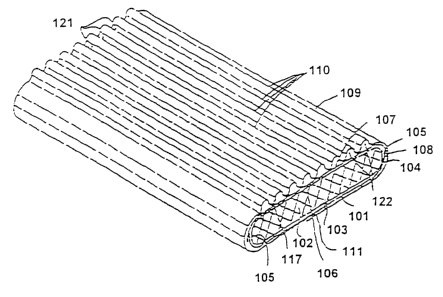
As is evident from attached Figs. 14 to 20, the different
embodiments of the depicted sanitary napkins exhibit basic
:structures which correspond to one another in the m<~in points.
For example, the backside liquid-impermeable cover sheet is
provided in the form of a garment-protecting foil lc)1 which is
disposed under the absorbent body 102 provided as wood pulp
?=luff pad in the area of. the backside 103 thereof, i.e., on the
;side disposed away from the wearer when the sanitary napkin is
applied. The garment-protecting foil 1C1 further extends with
P ',TEXT'P.4TEN'1 ~6s S9PC 1 W DOC
19
its longitudinal edges 104 around the lateral edge 105 of the
,absorbent body 102.
backing sheet 107 which may be, for example, a nonwoven sheet
extends with its surface over the frontside surface 106. The
:tacking sheet 107 as well extends with its longitudinal edges
108 around the side edge 105 of the absorbent body 102 and
overlaps with the longitudinal edges 104 of the garment-
r~rotecting foil 101. In this overlap area th<~se two parts are
bonded to each other in conventional manner.
On the backing sheet 107 there is provided a frontside liquid-
permeable cover sheet 109 which is provided with folds 110 in a
anner which will be described in further detail below. The
embodiments of the sanitary napkins shown in Figs. 14, 15 and
17 are so-called "fully wrapped sanitary napkins", 'wherein the
cover sheet 109, which may, for example, be formed of a
polypropylene card nonwoven, is wrapped around the absorbent
body 102, the backing sheet 107 and the cover sheet 109 on the
backside 103 and fixed centrally by an adhesive bond 111.
In the embodiments shown in Figs. 16 and 18, ~;ide flaps 112 are
Provided which are formed by laterally projecting, peripherally
bonded flaps 113, 114 of the frontside cover sheet 109 and a
backside cover sheet 115, respectively. The cover sheet 115 may
be made from nonwoven, as is in particular the case in the
embodiment shown in Fig. 16, which comprises a separate
garment-protecting foil 101. The garment-prc>tecting foil 101
may also be dispensed with, and the cover sheet can be made of
a liquid-impermeable material, for example, polyethylene foil
and thus functions as garment-protecting foil.
The different fold configurations used in the various
embodiments of the depicted sanitary napkins will now be
explained in further detail.
P ' TE;C'I"P.a'I'E VT'6>S9PC t W DOC
2ll 9401 1
''~,he folds 110 are formed by a suitable folding means in the
:unitary napkin manufacturing device such that the valley
portions 116 are disposed on the backing sheet 107 in
transverse direction of the napkin at a distance A, said
distance being in the range between 1 and 20 mm. A distance in
t:he range of from 3 t.o 5 mm was found 'to be particular
suitable. The valley portions 116 are fixed to the backing
~~heet 107 by longitudinally extending adhesive lines 117, which
are formed, for example, by a spray adhesive. The folds 110
project upwardly between adjacent valley portions 116, the
projecting height H being conceivable to range' between 1 to 20
mm. A projection height. in the range between 3 and 5 mm was
f=ound to be particularly suitable. The valley width F defined
by the adhesive lines 117 may be between 0.2 and 10 mm
dependent on the distance A and projecting height H. Care must
be taken that the valley width F is maximally half of the
distance A. At a distance A and a projecting height H of from 3
t:o 5 mm, valley widths of from 0.5 to 1 mm were found to be
useful.
In the embodiments of Figs. 14 to 16 eight folds 110 are
provided which are uniformly distributed over the entire width
of the absorbent body surface 102, the fold distance A being
~ibout 6 mm .
Tn the embodiment shown in Fig. 17, two peripheral stripes 118
each consisting of two folds 110 extending in longitudinal
direction of the sanitary napkin are provided, said folds being
provided at a distance A from one another and having a
projecting height H of about 6 mm. In the central ~~tripes 119
remaining between the two peripheral stripes 118 the liquid-
permeable cover sheet 109 lies evenly on the backing sheet 107
~~nd is additionally bonded thereto by a central adhe:~ive stripe
P ',TE.Y'I1P.4TEVT~,6589PC1 W DOC
219-01 1
21
117. It is also possible to provide a liquid-permeable bond
over the entire surface using small amounts oi= adhesive.
In the sanitary napkin embodiment shown in Fig. 18 there is
provided, symmetrically to the central plane L, a further fold
configuration with three folds 110 in addition to th.e folds 110
in the two peripheral stripes, with stripes 120 without folds
remaining between the central folds 110 anal the peripheral
folds 110.
.As is evident from the cross-sections of Fig. 15 to 17, the
grooves 121 between the folds 110 at the outside thereof, on
the one hand, and the tubes 122 extending beneath th.e folds 110
between the bonded valley portions 116, on the other hand, form
channels for distributing body fluids in longitudinal direction
of the sanitary napkin which are applied to the sanitary
:napkin .
It should be observed that suitable materials are to be
selected for the individual components of the sanitary napkin
~~f the invention from available materials in accordance with
the usual criteria commonly applied in the construction of such
sanitary materials and appropriate construction ma_asures are
to be applied. As to the latter, only by way of example,
attention is drawn to the fact that the adh~asive :stripes 117
should be designed such that a sealage of the surface of the
backing sheet 107 against liquid penetration is kept at a
minimum such that the absorbent surface of th.e sanitary napkin
is kept at a maximum. Accordingly, a spray adhesive may be
applied or a meltblown adhesive which is applied in small
lines. Laser, ultrasonic or thermal welding or sealing is also
conceivable.
Finally, Figs. 19 and 20 show embodiments of the absorbent
article of the invention wherein the absorbent body 205 is
P ~rsxrpa:Ewess~PCiw DOc
22 ~ 1 '9 4 01 ~
pleated. The articles shown in said Figures, moreover, contain
pleated cover sheet 203 which is bonded with an outer cover
:sheet 201 at connecting points 202 (Fig. 19;. The embodiment
:shown in Fig. 19 moreover shows a liquid-.impermeable cover
:sheet 204 which is referred to among ~=_xpert~~ also as
''polybaffle" .
The absorbent body which comprises at least one corrugated web
may comprise, apart from the above-mentioned materials card
nonwoven and spunbonded nonwoven, also an air-laid fibrous web,
.Laminates or the coform material specified further below. Wood
pulp/synthetic fiber mixtures are readidly capable to absorb
:Liquids up to 25 g/g liquid. In addition to an absorbent web,
t=he absorbent article may also comprise a superabsorber. These
:~uperabsorbers have a liquid absorbency of about 1 to 500 g/g
physiologic sodidum chloride solution. The absorbent capacity
:nor body fluids is about 1 g/g to 80 g/g.
:Ln particular mufti-layer laminates of perforated foils and
:~punbonded nonwovens or mufti-layer laminat~ss of perforated
:.oils and card nonwovens having a basis weight of about 20 to
200 g/m2, preferably 30 to 100 g/m2, in particular 42 g/m2
and/or a thickness of f:rorn 0.15 to 4.0 mm, preferably 0.3 to
.L.S mm, in particular 0.5 mm are suitable as liquid-permeable
<~over materials.
As component of the absorbent are suitable materials of card
nonwoven, a spundbonded nonwoven, web materia:L of a mixture of
wood pulp and synthetic fibers (Coform) , a c~ompacte=_d air-laid
wood pulp web (airlaid material) or an ai.rlaid. web of a mixture
of wood-pulp and synthetic fibrous web (the rmofixed airlaid
material). Suitable are furthermore prism and coform materials,
absorbent webs of airlaid woodpulp, wood pul:p/synthetic fiber
mixtures or synthetic fiber webs having a basis weight of from
<~bout 12 to 400 g/m2, preferably 50 to 150 g/m2, in particular
P ',TE'CTPATENT.6p89PC1 W DOC
23
219401 ~
100 g/m2 and/or thicknesses of from 0.1 to 3 mm, , preferably
0.2 to 2 mm, in particular 1 mm.
The bodyside cover sheet should preferably exhibit hydrophilci
properties. Possible further transfer sheets and/or materials
between the bodyside cover sheet and absorbent body may both
be hydrophilic as well as hydrophobic.
It is self-evident for the person skilled in the art, that the
pleated cover sheet 203 can also be replaced by a non-pleated
sheet. Even if only at least part of the absorbent body is
pleated, the lateral leak-proofness of the :sanitary article of
the invention is increased and an improved longitudinal
distribution of the absorbed liquid is achieved. Moreover, it
is a matter-of-course that both the liquid-permeable cover
sheet and the liquid-impermeable cover sheet of such an
absorbent article may be composed of an at least partially
corrugated absorbent body made of the materials described in
more detail above.
Fig. 21 shows an embodiment of the absorbent article of the
invention wherein the absorbent body 205 is corrugated, the
corrugations being of different heights. The corrugation height
H1 in the centre of the absorbent article is prefereably
maximal ten times higher than the corrugation height H2 in the
peripheral portions of the article.
The longitudinally corrugated webs (pleated webs) produced
according to the inveration are applied to ultra-thin absorbent
bodies. The performance data of corresponding absorbent
articles are summarized in Table 2.
The materials specified in Table 2, Prism,N~ Ekotec and CoformM
have the following properties:
0
P'TE'CTPATE\T.6589PC1W DOC
24
2194~Q1 1
Prism: Special spunbonded nonwoven having a high volume,
treated on one side or two sides, basis weights of from
about 12 to abaut 80 g/m2 . Prism 0 . Gi corresponds to a
basis weight of about 17 g/m2, Prism 1.0 corresponds to
a basis weight of about 35.0 g/m2.
Ekotec High loft card nonwoven, dried by hot air (hot through
air dried) , high volume, basis weight of from about 12
to about 70 g/m2.
Coform wood pulp/polypropylene mixture, fibrilized wood pulp
strengthened with spun PP fibers, basis weight of from
about 40 to about 400 g/m2.
The treatment of Prism on one side or two sides by means of an
Arivage method causes an improved liquid absorption and a
faster penetration of the liquid, especially if the material is
hydrophilized.
P ,TEXIIPATc?sT,6~B9PC1 W DOC
219401 1 ~-
~~=
~
i
,
NN h tD ~ ~ ~1~~ ~ ~ t0 N M c ~ c'O~~ ~ n-N
c , N D ~l. a
p
~y.,~ CC O - O O C~ cV C C C - C G C~ c~IN
;J~
.D
d
a
E
~..
N N ~ ~ ~ ~ ~ ~
f
v'~E '~ o ~ aNOc'~'~m ~ 'c~c~e~ c~~c~r '~ '~~ ~'~i 'e~c~c~
~
E o , , c
, r
w CVCV N fVCV CVCVCVc~'7 CVCVCV N CVNfV CVthf~c'7
c
c
c
0
a
a
ca
o~
o
E
'
o
d
~
CV~ OD~ lD fDfD~O ,~ N
a2
~ N
'
d
H
3 c~ ~ ~ ~ ~ ~~ ~ ' n ~ N i W
E
o c c c a r n,
~, ~ v O
'J COf.h h.COtDO1 O O O o7COc0 h
U,
O
E ~~ '~~'a u~c~~~ o o ~'
3
r
e0 CO C C O G OC C O O C ~7C G t7
~
c~
C
U
f: C~ ~ ~ ~ N ~ ~ ~ ~ ~ ~ ~ ~ani Q> ~l7
!~O O C t~
O_ .
CV CVc') CV~ fVCh CVCV~fI'~ N tVcVCVP1 CV~ CV t~fVt0~ CV
id
OI O1 O 01 O) O
~ W ~ y
E mo ~no n o n o u~
'C O O ~ O ~- O ~ O ~ O
O~ V ~ ~ V~ V V ~ ~~ ~
NN ~ N N O E N C N ~ ~ N N ~ ~ N ~ H
U
O g a ~ Og t ~ O ~ c J O R ' d pg ~ a O g a
' /1 ' a ' ~
a
2a I~c C~C t c n L~ a CC c
~ . ~
c
w
O v
~ .C 'OG Q O
. ..
~ ~ -
d
E 3 ~ E C
E o ~a E o o is ea
'C N C O It7 C I C
:: CLC '
r ~ ~ N D , 7
ca N N
~ N
E a ~ ~ ~ ~ > d a ; , :.' d
..
v d ~ ~ m a~ d i ~ m m
'
o ~ E o ~ ' c c
$ ~ ~ ~ $