Note: Descriptions are shown in the official language in which they were submitted.
CA 02194027 2001-06-07
CA9-96-O 1 S I
AN IMAGING SYSTEM USING A DATA TRANSMITTING
LIGHT SOURCE FOR SUBJECT ILLUMINATION
S Field of the Invention
The present invention relates generally to imaging systems that use light
sources such as infrared
light for the purposes of transmitting image information from a camera to
another device such as
a computer system incorporating a light receiving device adapted to receive
data.
Background of the Invention
Video cameras are used with computers for capturing images for uses such as
video conferencing
or storage. One difficulty in using a video camera in a typical office is
caused by lighting. Office,
often have overhead lighting which creates undesirable shadows that result in
unsatisfactory image
pickup.
IS
Most digital or video cameras use a CCD (Charge Couple Device) as an
electronic sensor to
capture an image. Depending on the material of the CCD, it may have a wide
radiometric
spectrum ranging from blue (400 Nm) up to mid-inti-ared (24()0 Nm) (the
visible spectrum is ti-om
380 to 780 Nm).
The most recent development in communication between computers and other data
processing
systems has been the use of infrared light to transrer data between the
system;. Inti~ared transceiver
communication systems are used to connect workstation computers. lap-top
CA 02194027 2001-06-07
CA9-96-O 15
computers to each other and to other data handling system such as printers in
the form of local
access networks (LANs). These infrared LANs can provide similar capabilities
to wired LANs
without requiring wire connections. In addition, infrared communications have
been adapted to
transmit imaging data obtained by digital or video cameras to data processing
systems such as
computers for the purposes of video conferencing or further processing of the
images.
Many companies have adopted the standards proposed by the IrDA (Infrared Data
AssociationTM)
for the transmission and reception of data using infrared light. The infrared
light wave lengths
adopted for use under the IrDA guidelines is 870 nm. This is in the near
infrared range (close to
l U the visible spectrum). We have found that many CCD video cameras will
respond to the inti-ared
light near this wavelength. Infrared emitting LED's (Light Emitting Diodes)
are readily available
that transmit infrared light in the same region and also can provide suitable
infrared sources.
We have found that the following video cameras will respond readily to
infrared light in this
1 ~ region:
I . Connectix QuickCamT"'' from Connectix Corp. Connectix mounts an infrared
filter
in front of the CCD of the QuickCam video camera to Iilter out Infrared (IR)
light.
This is removed to permitted it to respond to IR light.
?U
2. GBC CCD-506 from CCTV Cusp. is a typical CCD based low light black and
white surveillance camera.
3. Sony Vidco 8 Camcorder.
?5
CA 02194027 2001-06-07
CA9-96-015 3
Cameras in Low Light Conditions
While human vision can handle a wide latitude of light intensity (dark vs
bright areas), CCDs are
fairly limited. This creates problems when capturing an image of a person
especially using
overhead lighting. Dark shadows appear under the eyebrows. While the human eye
differentiates
these as only shadows, a CCD camera may see them as virtually black due to its
limited ability to
handy contrast.
The solution most used by the photographers to solve this problem is to
provide an additional
visible light source at or near the camera to illuminate the subject. This
floods the subject with
light minimizing the impact of overhead or' poor lighting and reduces the
contrast range of the
lighting to permit satisfactory imaging.
In video conferencing or other applications which use live video, the image
must be captured by
the camera and sent to a computer or other data processing system. As
discussed previously. one
I S technique for communicating ti-om camera to a computer (such as a PC ) is
to use infrared light.
Summary of the Invention
We have found that it is possible to use the inti-ared light source that is
used to transmit the image
information from a video camera or a digital camera to a computer to also
illuminate the subject
satisfactorily. The present invention provides an imaging system that can
illuminate the subject
satisfactorily with light such as infrared light ti-om its infrared
transmission source that is used to
transmit information from the camera to an image recording or data processing
system.
Advantageously the system will include camera such as a video camera having an
image sensor
sensitive to visible and infrared light. A light Emitting device such as an
inti-ared LED (or an LED
operating in the visible spectrum) is associated
CA 02194027 2001-06-07
CA9-9G-O 15
with the camera in order to transmit image data output from the camera.
Preferably, the light
emitting device is adapted to emit light or infrared light in a divergent
beam.
Advantageously, the Light Emitting Device is positionable with respect to the
camera so that it can
illuminate a subject with its light within the field of view of the camera.
Advantageously, the light
emitting device can be positioned on the camera to project light forwardly to
the subject or can be
incorporated in a separate device which is connected to the camera and aimed
at the subject in
order to provide illumination.
1 U In one aspect of the invention, a controller is provided for controlling
the light emitter to transmit
image data to the recording or data processing system at the same time as an
image is being
captured by the image sensor of the camera.
In another aspect of the invention, the controller can be adapted to permit
the camera to capture
l S an image at the same time as r_ransmittin~ data of an image previously
captured. Additional
intiared light (such as in the fur-~n of false data) can be added to the
transmission to provide
improved illumination of the subject if required.
The inti-ared emitter can be mounted on the camera to point in the same
direction as the lens.
2U
Normally the camera will be used in conjunction with another unit of image
processing ur data
processing equipment such as ~~ computer which will itself have an infrared
transceiver. The
inti-arcd transceiver of the computer can also be adapted to illuminate a
subject being photographed
by suitable placement and aiming as will be understood readily by those
skilled in the art.
CA 02194027 2001-06-07
CA9-96-015
Generally, in its broadest form, the invention uses the same infrared
transceiver or emitter that is
used for communication between camera and an auxiliary unit with which it is
in communication
to provide illumination of a subject being photographed so that there will be
sufficient subject
illumination for successful imaging.
When the infrared emitter of the camera is used to illuminate the subject at
the same time as it is
transmitting image data conservation of energy is achieved as no extra energy
need be expended
on illumination. This will enable the camera, which is typically battery
powered, to be used for a
longer period of time on each charge, or if powered from the mains will
achieve a reduction in
energy expense.
A Brief Description of the Drawings
Additional features of the invention will be more readily apparent from the
following detailed
description and claims when taken in conjunction of the drawings in which;
Figure 1 is a top view of block diagram of one embodiment of the invention in
which the
auxiliary unit (computer) is placed between the subject and the camera;
Figure 2 is a side view of the same embodiment of the invention;
Figure 3 is a top view of another embodiment of the invention in which the
camera is
located in front of the auxiliary unit;
Figure 4 is a side view of the embodiment of figure 3;
Figure 5 is another embodiment of the invention illustrating the use of the
invention with
a tethered inti-ared transceiver associated with the camera unit.
Description of the Preferred Embodiments of the Invention
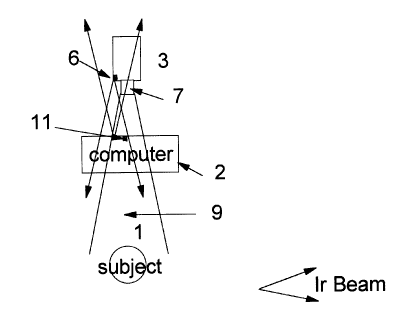
Referring to Figure I and Figure 2, there is shown one embodiment of the
invention in which a
camera (3) is aimed both at the auxiliary unit (computer (2)) and the subject
( l ) who may also
CA 02194027 2001-06-07
CA9-9G-O 15
be operating the computer (2). In this scenario, the camera (3) is capturing
pictures of the operator
and sending them to the computer. The communications between the camera and
the computer
is by an infrared link such as IrDA link in which an IR transceiver (6) on the
camera is sending
image data to an IR transceiver ( 1 1 ) at the computer or auxiliary unit (2)
by means of infrared
transceiver (6) on the unit.
In a traditional setup not incorporating the advantages of the invention, a
light is placed over the
camera aimed at the face of the person to overcome shadows created by overhead
or otherwise
poor lighting.
In the method of the invention, the camera l3 ) is aimed at both the person (
1 ) and the computer (2).
The field of view (9) of the lens (7) of the camera is typically aimed to
capture the face ( I O) of the
subject ( 1 ). The infrared emitter ofthe transceiver is typically an LED
associated with the camera
which may be on the front of the camera as illustrated in Figures 1 and 2 or
tethered to the camera.
I 5 In both instances, it is aimed both at the face of the person and the
computer (2). This is possible
when an IrDA conforming LED is used. An IrDA conforming LED is required to
have at least a
degree cone of coverage off the centre axis in the direction of emission. This
results in a cone
of coverage of at least 30 degrees. Tht= LED will still provide some
illumination outside of the 30
degree cone but to a lesser amount.
Referring to a system equipped W communicate using IrDA transmission protocol.
In order to send
a picture ti-om the camera (3) tc> c«mhuter (?). the controUler of the camera
(which need not be
shown), turns the LED on and ol~f in predefined data transmission pattern as
defined in the IrDA
standard which can be obtained ti-on~ the IrDA Association at P.O.Box 3883,
Walnut Creek, CA
2~ 94598. As will be appreciated by those skilled in the art. the amount or
quantity of the infrared
light illuminating the face or suhje~t can he calculated based on the
CA 02194027 2001-06-07
CA9-96-015
data stream structure and data sent. Additional infrared light can be
transmitted, which we will call
"false data", that does not need to conform to communications standards (and
preferably will not
conform to the communications standards to avoid miscommunication) can be sent
if additional
light is needed to illuminate the subject. If this data does not conform to
the communications
standards of the IrDA, this data will be rejected by the computer as it is not
in the con-ectly defined
data stream. The additional "false" data will provide additional illumination
to the subject as can
be appreciated.
The process of capturing an image by the camera and the transmission of the
image to computer
can be appreciated as a two-step operation. These two steps can be concurrent
or sequential.
If the image capture is concurrent with the transmission of the previously
captured image, the
quality of the image capture can be affected by the variation or ir-egularity
in the emission and
infrared intensity of the IR emitter due to the data pattern being
transmitted. For instance, if the
I 5 image being transmitted has a large amount of dark areas then a
proportionally larger amount of
infrared data or energy is transmitted, and conversely if data for the light
portion of an image is
being transmitted there will be proportionally less infrared radiation
available to illuminate the
subject. This may occur if the exposure rate of the camera is shower than the
time required to
transmit the image. In an NTSC conforming video signal, the capture rate used
in 30 images per
second. Under higher lighting conditions, the exposure of the camera will be
much shorter than
one-thirtieth of a second. The result may be that sequential images will be
exposed with different
light intensities and the image observable transmitted by the camera will
exhibit a Clashing or
strobe effect. In this situation, the camera will acquire a means for
adjusting the exposure on a
frame-by-frame basis to compensate for- this effect. This can be achieved
electronically by
processing the image obtained by the camera which may require additional
processing circuitry
in the camera or to be associated with the image transmission being processed.
CA 02194027 2001-06-07
CA9-9G-O 15 g
If the exposure used by the camera is long enough, then the amount of infrared
data should be
sufficient to result in consistent illumination, but there may be a residual
effect dependent on the
data sent caused by the image being photographed by the camera.
As previously indicated, if the exposure rate of the camera is shorter than
the time required to
transmit the image, a flashing or strobe effect may result. This strobe effect
caused by the varying
light emitted from the LED, can be corrected by controlling the intensity of
the LED light source
emissions during image capture. This will must easily be achieved if the
functions of image capture
and image transmission are done sequentially. In many video conferencing or
image capture
systems, the capture rate is much slower than an NTSC' system, with typical
rates of 15 frames per
second or less. These systems allov~ more time for image transmission versus
this image capture.
The intensity of the LED light source can be contruiled by changing the duty
cycles of the LEDs
used or by changing their current levels. With a higher clutv cycle or a
higher current, more inti-ared
I 5 light will be emitted. This can be done by an intensity control circuit or
controller associated with
the IR transceiver. 1n the case ufan image chat is lar~~er or contains more
details or image intensity
levels, there is more data being transmitmd and tharetorc likely to bc: more
infrared light available
for illumination. A larger image implies that more pixels are being recorded
and thus more data
will be rccluired for transmission prw idin'~ more illumination.
2U
A typical video camera includes a promss~~r which can and is used to control
exposure, timing,
aperture, and such. Typically tl~e proce,aur is preprogrammed at the
manufacturer with its own
tinnware. For the purposes ut this invennun. tloe prmcssor or an auxiliary
controller can be used
to control the an~c~unt of illuminaticm ~n~ittW by the f_L:Us stud also the
timime uf~tl~e
CA 02194027 2001-06-07
CA9-96-015
illumination as will be well appreciated by those familiar with the video
camera or digital camera
technology.
At a rate of 15 frames per second, an image must be transmitted once every 67
milliseconds.
In this time period, a 32 kilobyte image of 320 X 200 pixels with I 6 gray
levels can be sent using
a four megabyte per second infrared link (4 Mbps) [in conformity with the IrDA
association
standards]. However, if the exposure time is in the one millisecond range, it
is then possible to
have non-overlapping exposure and transmission (ie sequential exposure and
transmission) at 15
frames per second using a 4 Mbps inti-ared link. It is possible to support
larger image sizes with
more intensity levels as the frame rate will be correspondingly decreased if
the same infrared link
transmission rate is used.
~~ith an rxpusure time of 1 millisecond, it is possible to control the
infrared light source to emit
a burst of inti-ared light for the period of the exposure by turning it on
independently of the data
I S transmission. fn that case the light source will behave like a Clash unit.
W'e have found that using image transmission data to illuminate the subject
while the camera is
sending the picture to the computer will provide sufticient illumination for
the next image capture.
V%e have found that this results in good illumination for a black and white
camera, as described in
?!i the poor li~l~ting situation with no additional LED power or additional
li~~htin~~ required.
There <ire a number of video cameras available that have 0.3 lumex sensitivity
and it has been
tound that the invention herein provides good results with these cameras.
?~ In aci~lition, us depicted in Figures 3 and 4, ii the camera is positioned
between tl~e subject and
CA 02194027 2001-06-07
CA9-9~-015 10
the computer and the computer (2) is provided with an infrared transceiver ( l
1 ) which projects
infrared light towards the camera (3) acid thus incidentally towards the
person being photographed
by the camera, the infrared transceiver used by the computer ( I 1 ) can be
used to illuminate the
subject in similar manner. In this instance, it is presumed that the infrared
transceiver of the
camera is position to accept and transmit infrared data to the rear towards
the computer.
As has been mentioned previously, it is possible to use infrared transceivers
which are tethered
either to the camera or computer and can thus be positioned to provide
illumination towards the
subject depending on the position of the camera or computer as described in
relation to Figures 1
and 2 and 3, and 4 in a similar manner.
Figure 5 illustrates such a system in which the tethered transceiver (C)
illuminates the computer
(2) while the computer transceiver (1l) illuminates the subject. V~hile this
description has
described the invention in detail in relation to video ramcr<ts, we have found
that it applies as well
IS to digital .still cameras that art sensitive in the near infrared range as
well as tmin'~ infrared
connnumcation to transmit information to a recurtlin~~ unit or data procm;in~
.vstmo.
The invention works best with monochrome or black and white camera systems
which have
formed the basis of our development et~torts.
?0
While the invention has been described in conjunction with intagin'u systems
using infrared
communication, it will be appreciated that other light mmn~unic titan svstm
tc~ which the camera
sensors ofthe system are sensitim may alw bmscd.
2~ Although this invention has been des~ribmi in ternos uf~use off intiwred
emitters. tranwnittcrs or
L.EDs, it will be readily appreciated that f_EDs cw other emitmrs c>peratin'~
in the visible light
spectrum mug provide similar capabilities where thaw I_1--IO arc uwcl in ;i
hi!~h >pecd li«ht
CA 02194027 2001-06-07
CA9-96-015 1 I
commumcatton system similar to the infrared system which has been described.
While the present invention has been described with reference to a few
specific embodiments, the
description is illustrative of the invention and is not to be construed as
limiting the invention.
Various modifications to the invention may be made by those skilled in the art
without departing
the true spirit and scope of the invention as defined by the appended claims.