Language selection

Search

Patent 2194111 Summary

Third-party information liability

Some of the information on this Web page has been provided by external sources. The Government of Canada is not responsible for the accuracy, reliability or currency of the information supplied by external sources. Users wishing to rely upon this information should consult directly with the source of the information. Content provided by external sources is not subject to official languages, privacy and accessibility requirements.

Claims and Abstract availability

Any discrepancies in the text and image of the Claims and Abstract are due to differing posting times. Text of the Claims and Abstract are posted:

  • At the time the application is open to public inspection;
  • At the time of issue of the patent (grant).
(12) Patent: (11) CA 2194111
(54) English Title: AUXILIARY HANDLE OF A STEERING WHEEL
(54) French Title: POIGNEE DE COMMANDE AUXILIAIRE POUR VOLANT DE DIRECTION
Status: Expired and beyond the Period of Reversal
Bibliographic Data
(51) International Patent Classification (IPC):
  • B62D 1/22 (2006.01)
  • B62D 1/04 (2006.01)
(72) Inventors :
  • CHAO, HUA-JEN (Taiwan, Province of China)
(73) Owners :
  • HUA-JEN CHAO
(71) Applicants :
  • HUA-JEN CHAO (Taiwan, Province of China)
(74) Agent: KIRBY EADES GALE BAKER
(74) Associate agent:
(45) Issued: 1999-10-05
(22) Filed Date: 1996-12-30
(41) Open to Public Inspection: 1998-06-30
Examination requested: 1996-12-30
Availability of licence: N/A
Dedicated to the Public: N/A
(25) Language of filing: English

Patent Cooperation Treaty (PCT): No

(30) Application Priority Data: None

Abstracts

English Abstract


An auxiliary handle including a handle,
a rotary member, a bottom cap , and a mounting
device , wherein the rotary member and the bottom
cap are secured to the handle at the bottom side
and then fastened to a steering wheel by the
mounting device , for permitting the user to turn
the steering wheel by hand through the handle.


French Abstract

Poignée de commande auxiliaire comportant une poignée, un organe rotatif, une partie inférieure et un dispositif de montage sous lequel l'organe rotatif et la partie inférieure sont assujettis pour fixation au volant; la poignée de commande auxiliaire permet à l'utilisateur de tourner manuellement le volant de direction.

Claims

Note: Claims are shown in the official language in which they were submitted.

- 8 -
I claim:
1. An auxiliary handle fastened to a
steering wheel for turning said steering wheel by
hand, comprising:
a mounting device having a mounting
unit, a fastening screw unit mounted on said
mounting unit and moved between two opposite
positions, permitting said mounting unit to be
opened for mounting on said steering wheel and then
closed when installed, and a coupling rod raised
from said mounting unit and defining an axial
through hole ;
a rotary member having a core , and a
screw hole disposed at the center of said core and
connected to the axial through hole of the
coupling rod of said mounting device; and
a handle connected to said mounting device through
said rotary member, said handle comprising a hand
grip having a bottom chamber which receives said
rotary member, a periphery groove and two bottom
screw holes, a collar mounted on said periphery
groove around said hand grip , and a bottom
cap mounted around the coupling rod of said
mounting device and fixedly connected to the screw
holes of said hand grip to hold said rotary member

- 9 -
inside the bottom chamber of said hand grip.
2. The auxiliary handle of claim 1
wherein said hand grip of said handle is
ergonomically engineered, having a plurality of
finger recesses.
3. The auxiliary handle of claim 1
wherein said hand grip comprises a top recess, a
center through hole through the center of said top
recess, and a top cap mounted within said top
recess and having a female screw fastened to said
center through hole.

Description

Note: Descriptions are shown in the official language in which they were submitted.


-1- 21941 1 1
AUXILIARY HANDLE OF _ STEERING WHEEL
BACKGROUND OF THE INVENTION
The present invention relates to a
steering wheel auxiliary device, and more
specifically to an auxiliary handle adapted for
fastening to a steering wheel for permitting the
driver to manipulate the steering wheel through the
auxiliary handle.
Attaching an auxiliary handle to a
steering wheel for turning by hand with less
effort, has become popular. Figure 1 shows an
auxiliary handle installed in a steering wheel
according to the prior art. This auxiliary handle
is comprised of two arched clamping plates hinged
together and adapted for fastening to a steering
wheel, a screw member threaded into respective
screw holes in the arched clamping plates to fix
them together, and a rounded handle mounted around
the screw member. This structure of auxiliary
handle has drawbacks. One drawback of this
structure of auxiliary handle is that the friction
force resulted between the inside wall of the
rounded handle tends and the periphery of the screw
member handle may causes the rounded handle to be

-2- 21941 t ~
stuck. When the rounded handle is stuck, the
driver will be unable to control the steering wheel
through the auxiliary handle smoothly.
Furthermore, when a sudden force is applied to the
steering wheel through the auxiliary handle, the
arched clamping plates may be turned relative to
the steering wheel, causing the steering wheel to
be escaped from the control of the driver, and the
covering leather of the steering wheel to be
damaged.
SUMMARY OF THE INVENTION
It is one object of the present
invention to provide an auxiliary handle which
eliminates the aforesaid problems and, which can be
easily installed in a steering wheel for a positive
steering control. It is another object of the
present invention to provide an auxiliary handle
which uses a bearing-like rotary member to support
the hand grip, permitting the hand grip to be
smoothly turned to positively control the steering
wheel. According to still another object of the
present invention, the mounting device of the
auxiliary handle is internally mounted with a
rubber cushion, so that the mounting device can be

2i941 1 1
--3--
firmly secured to the steering wheel, and does nct
damage the leather covering of the steering wheel
when turned. According to still another aspect of
the present invention, the auxiliary handle can be
made having a single color or multiple colors, or a
decorative design. According to still another
aspect of the present invention, the auxiliary
handle is ergonomically engineered, having a
plurality of finger recesses for the griping of the
fingers.
BRIEF DESCRIPTION OF THE DRAWINGS
Fig. 1 shows an auxiliary handle
installed in a steering wheel according to the
prior art;
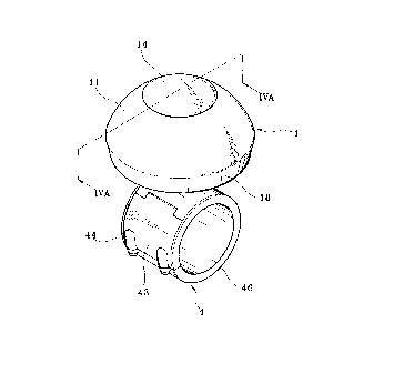
Fig. 2 is an elevational view of an
auxiliary handle according to the present
invention;
- Fig. 3 is an exploded view of the
auxiliary handle shown in Figure 2;
Fig. 4A is a sectional view taken along
line A-A of Figure 2;
Fig. 4B is similar to Figure 4A but
showing the mounting unit opened;
Fig. 5 is an applied view of the present

- ' 21941 1 1
-4-
invention, showing the auxiliary handle fastened to
a steering wheel; and
Fig. 6 is an elevational view of an
alternate form of the auxiliary handle according to
the present invention.
DETAILED DESCRIPTION OF THE PREFERRED EMBODIMENT
Referring to Figures 2 and 3, an
auxiliary handle in accordance with the present
invention is generally comprised of a handle 1, a
rotary member 2, a bottom cap 3, and a mounting
device 4.
The handle 1 comprises a hand grip 11, a
top cap 14, and a collar 18. The hand grip 11
comprises a top recess 12, a bottom chamber 16
adapted for receiving the rotary member 2, a center
through hole 13 disposed in communication between
the top recess 12 and the bottom chamber 16, two
bottom screw holes 161 at two opposite sides of the
bottom chamber 16, and a periphery groove 17. The
top cap 14 is mounted within the top recess 12 of
the hand grip 11, having a female screw 141 fitted
into the center through hole 13 of the hand grip 11
and secured thereto by a screw 15. The collar 18

21 941 1 1
is mounted around the periphery groove 17 of the
hand grip 11. The rotary member 2 is a metal
bearing mounted within the bottom chamber 16 of the
hand grip 11, having a core 22 and a screw hole 21
at the center of the core 22. The bottom cap 3
comprises a center hole 31, two mounting holes 32
at two opposite lateral sides respectively fastened
to the bottom screw holes 161 of the hand grip 11
by a respective screw 33. The mounting device 4
comprises a mounting unit 43, which is comprised of
a plurality of plates 42 hinged together, a
fastening screw unit 44 mounted on the mounting
unit 43 and moved between a first position to close
the mounting unit 43 (see Figure 4A) and a second
position to open the mounting unit 43 (see Figure
4B), a coupling rod 41 raised from the periphery of
one plate 42 of the mounting unit 43 and defining
an axial through hole 411 through the corresponding
plate 42 of the mounting unit 43. The coupling rod
41 is inserted through the center hole 31 of the
bottom cap 3, and connected to the screw hole 21 of
the core 22 of the rotary member 2 by a screw 45.
Further, a rubber cushion 46 is mounted around the
inside wall of the mounting unit 43.

- 21 941 1 1
--6--
Referring to Figures 4A and 4B, when in
use, the fastening screw unit 44 is moved to the
second position to open the mounting unit 43,
permitting the mounting unit 43 to be mounted on
the steering wheel 5, and then the fastening screw
unit 44 is moved to the first position to close the
mounting unit 43, causing the mounting unit 43 to
be fixed to the steering wheel 5. Because the
rubber cushion 46 is mounted around the inside wall
of the mounting unit 43, the installation of the
auxiliary handle does not damage the covering of
the steering wheel 5 when the steering wheel 5 is
turned. Furthermore, the rubber cushion 46
enables the auxiliary handle to be firmly fixed to
the steering wheel 5.
Referring to Figure 5, when the
auxiliary handle is fastened to the steering wheel
5, the user can turn the steering wheel through the
auxiliary handle.
Referring to Figure 6, the hand grip 11
may be ergonomically engineered, having a plurality
of finger recesses 11' spaced around the border.
Through the finger recesses 11', the hand grip 11

21 941 ~ 1
-7-
can be positively seized with the hand.
Furthermore, the hand grip 11 of the handle 1 can
have a single color or multiple colors, or be
decorated with a design.

Representative Drawing
A single figure which represents the drawing illustrating the invention.
Administrative Status

2024-08-01:As part of the Next Generation Patents (NGP) transition, the Canadian Patents Database (CPD) now contains a more detailed Event History, which replicates the Event Log of our new back-office solution.

Please note that "Inactive:" events refers to events no longer in use in our new back-office solution.

For a clearer understanding of the status of the application/patent presented on this page, the site Disclaimer , as well as the definitions for Patent , Event History , Maintenance Fee  and Payment History  should be consulted.

Event History

Description Date
Inactive: IPC from MCD 2006-03-12
Time Limit for Reversal Expired 2001-01-02
Letter Sent 1999-12-30
Inactive: Cover page published 1999-10-05
Grant by Issuance 1999-10-05
Inactive: Final fee received 1999-07-09
Pre-grant 1999-07-09
Letter Sent 1999-02-26
Notice of Allowance is Issued 1999-02-26
Inactive: Status info is complete as of Log entry date 1999-02-15
Inactive: Application prosecuted on TS as of Log entry date 1999-02-15
Inactive: Approved for allowance (AFA) 1999-01-06
Application Published (Open to Public Inspection) 1998-06-30
All Requirements for Examination Determined Compliant 1996-12-30
Request for Examination Requirements Determined Compliant 1996-12-30

Abandonment History

There is no abandonment history.

Maintenance Fee

The last payment was received on 1998-10-26

Note : If the full payment has not been received on or before the date indicated, a further fee may be required which may be one of the following

  • the reinstatement fee;
  • the late payment fee; or
  • additional fee to reverse deemed expiry.

Please refer to the CIPO Patent Fees web page to see all current fee amounts.

Fee History

Fee Type Anniversary Year Due Date Paid Date
MF (application, 2nd anniv.) - small 02 1998-12-30 1998-10-26
Final fee - small 1999-07-09
Owners on Record

Note: Records showing the ownership history in alphabetical order.

Current Owners on Record
HUA-JEN CHAO
Past Owners on Record
None
Past Owners that do not appear in the "Owners on Record" listing will appear in other documentation within the application.
Documents

To view selected files, please enter reCAPTCHA code :


To view images, click a link in the Document Description column. To download the documents, select one or more checkboxes in the first column and then click the "Download Selected in PDF format (Zip Archive)" or the "Download Selected as Single PDF" button.

List of published and non-published patent-specific documents on the CPD .

If you have any difficulty accessing content, you can call the Client Service Centre at 1-866-997-1936 or send them an e-mail at CIPO Client Service Centre.


Document
Description 
Date
(yyyy-mm-dd) 
Number of pages   Size of Image (KB) 
Abstract 1997-05-02 1 10
Cover Page 1997-05-02 1 13
Description 1997-05-02 7 172
Claims 1997-05-02 2 41
Drawings 1997-05-02 6 132
Cover Page 1998-07-02 1 32
Representative drawing 1998-07-02 1 8
Cover Page 1999-09-29 1 31
Representative drawing 1999-09-29 1 7
Reminder of maintenance fee due 1998-09-01 1 115
Commissioner's Notice - Application Found Allowable 1999-02-26 1 164
Maintenance Fee Notice 2000-01-27 1 178
Correspondence 1999-07-09 1 45
Prosecution correspondence 1996-12-30 3 129
Correspondence related to formalities 1997-03-26 1 51