Sélection de la langue

Search

Sommaire du brevet 2194111 

Énoncé de désistement de responsabilité concernant l'information provenant de tiers

Une partie des informations de ce site Web a été fournie par des sources externes. Le gouvernement du Canada n'assume aucune responsabilité concernant la précision, l'actualité ou la fiabilité des informations fournies par les sources externes. Les utilisateurs qui désirent employer cette information devraient consulter directement la source des informations. Le contenu fourni par les sources externes n'est pas assujetti aux exigences sur les langues officielles, la protection des renseignements personnels et l'accessibilité.

Disponibilité de l'Abrégé et des Revendications

L'apparition de différences dans le texte et l'image des Revendications et de l'Abrégé dépend du moment auquel le document est publié. Les textes des Revendications et de l'Abrégé sont affichés :

  • lorsque la demande peut être examinée par le public;
  • lorsque le brevet est émis (délivrance).
(12) Brevet: (11) CA 2194111
(54) Titre français: POIGNEE DE COMMANDE AUXILIAIRE POUR VOLANT DE DIRECTION
(54) Titre anglais: AUXILIARY HANDLE OF A STEERING WHEEL
Statut: Périmé et au-delà du délai pour l’annulation
Données bibliographiques
Abrégés

Abrégé français

Poignée de commande auxiliaire comportant une poignée, un organe rotatif, une partie inférieure et un dispositif de montage sous lequel l'organe rotatif et la partie inférieure sont assujettis pour fixation au volant; la poignée de commande auxiliaire permet à l'utilisateur de tourner manuellement le volant de direction.


Abrégé anglais


An auxiliary handle including a handle,
a rotary member, a bottom cap , and a mounting
device , wherein the rotary member and the bottom
cap are secured to the handle at the bottom side
and then fastened to a steering wheel by the
mounting device , for permitting the user to turn
the steering wheel by hand through the handle.

Revendications

Note : Les revendications sont présentées dans la langue officielle dans laquelle elles ont été soumises.


- 8 -
I claim:
1. An auxiliary handle fastened to a
steering wheel for turning said steering wheel by
hand, comprising:
a mounting device having a mounting
unit, a fastening screw unit mounted on said
mounting unit and moved between two opposite
positions, permitting said mounting unit to be
opened for mounting on said steering wheel and then
closed when installed, and a coupling rod raised
from said mounting unit and defining an axial
through hole ;
a rotary member having a core , and a
screw hole disposed at the center of said core and
connected to the axial through hole of the
coupling rod of said mounting device; and
a handle connected to said mounting device through
said rotary member, said handle comprising a hand
grip having a bottom chamber which receives said
rotary member, a periphery groove and two bottom
screw holes, a collar mounted on said periphery
groove around said hand grip , and a bottom
cap mounted around the coupling rod of said
mounting device and fixedly connected to the screw
holes of said hand grip to hold said rotary member

- 9 -
inside the bottom chamber of said hand grip.
2. The auxiliary handle of claim 1
wherein said hand grip of said handle is
ergonomically engineered, having a plurality of
finger recesses.
3. The auxiliary handle of claim 1
wherein said hand grip comprises a top recess, a
center through hole through the center of said top
recess, and a top cap mounted within said top
recess and having a female screw fastened to said
center through hole.

Description

Note : Les descriptions sont présentées dans la langue officielle dans laquelle elles ont été soumises.

-1- 21941 1 1
AUXILIARY HANDLE OF _ STEERING WHEEL
BACKGROUND OF THE INVENTION
The present invention relates to a
steering wheel auxiliary device, and more
specifically to an auxiliary handle adapted for
fastening to a steering wheel for permitting the
driver to manipulate the steering wheel through the
auxiliary handle.
Attaching an auxiliary handle to a
steering wheel for turning by hand with less
effort, has become popular. Figure 1 shows an
auxiliary handle installed in a steering wheel
according to the prior art. This auxiliary handle
is comprised of two arched clamping plates hinged
together and adapted for fastening to a steering
wheel, a screw member threaded into respective
screw holes in the arched clamping plates to fix
them together, and a rounded handle mounted around
the screw member. This structure of auxiliary
handle has drawbacks. One drawback of this
structure of auxiliary handle is that the friction
force resulted between the inside wall of the
rounded handle tends and the periphery of the screw
member handle may causes the rounded handle to be

-2- 21941 t ~
stuck. When the rounded handle is stuck, the
driver will be unable to control the steering wheel
through the auxiliary handle smoothly.
Furthermore, when a sudden force is applied to the
steering wheel through the auxiliary handle, the
arched clamping plates may be turned relative to
the steering wheel, causing the steering wheel to
be escaped from the control of the driver, and the
covering leather of the steering wheel to be
damaged.
SUMMARY OF THE INVENTION
It is one object of the present
invention to provide an auxiliary handle which
eliminates the aforesaid problems and, which can be
easily installed in a steering wheel for a positive
steering control. It is another object of the
present invention to provide an auxiliary handle
which uses a bearing-like rotary member to support
the hand grip, permitting the hand grip to be
smoothly turned to positively control the steering
wheel. According to still another object of the
present invention, the mounting device of the
auxiliary handle is internally mounted with a
rubber cushion, so that the mounting device can be

2i941 1 1
--3--
firmly secured to the steering wheel, and does nct
damage the leather covering of the steering wheel
when turned. According to still another aspect of
the present invention, the auxiliary handle can be
made having a single color or multiple colors, or a
decorative design. According to still another
aspect of the present invention, the auxiliary
handle is ergonomically engineered, having a
plurality of finger recesses for the griping of the
fingers.
BRIEF DESCRIPTION OF THE DRAWINGS
Fig. 1 shows an auxiliary handle
installed in a steering wheel according to the
prior art;
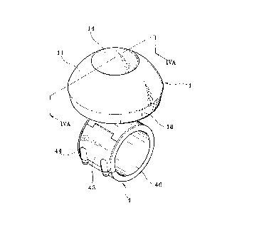
Fig. 2 is an elevational view of an
auxiliary handle according to the present
invention;
- Fig. 3 is an exploded view of the
auxiliary handle shown in Figure 2;
Fig. 4A is a sectional view taken along
line A-A of Figure 2;
Fig. 4B is similar to Figure 4A but
showing the mounting unit opened;
Fig. 5 is an applied view of the present

- ' 21941 1 1
-4-
invention, showing the auxiliary handle fastened to
a steering wheel; and
Fig. 6 is an elevational view of an
alternate form of the auxiliary handle according to
the present invention.
DETAILED DESCRIPTION OF THE PREFERRED EMBODIMENT
Referring to Figures 2 and 3, an
auxiliary handle in accordance with the present
invention is generally comprised of a handle 1, a
rotary member 2, a bottom cap 3, and a mounting
device 4.
The handle 1 comprises a hand grip 11, a
top cap 14, and a collar 18. The hand grip 11
comprises a top recess 12, a bottom chamber 16
adapted for receiving the rotary member 2, a center
through hole 13 disposed in communication between
the top recess 12 and the bottom chamber 16, two
bottom screw holes 161 at two opposite sides of the
bottom chamber 16, and a periphery groove 17. The
top cap 14 is mounted within the top recess 12 of
the hand grip 11, having a female screw 141 fitted
into the center through hole 13 of the hand grip 11
and secured thereto by a screw 15. The collar 18

21 941 1 1
is mounted around the periphery groove 17 of the
hand grip 11. The rotary member 2 is a metal
bearing mounted within the bottom chamber 16 of the
hand grip 11, having a core 22 and a screw hole 21
at the center of the core 22. The bottom cap 3
comprises a center hole 31, two mounting holes 32
at two opposite lateral sides respectively fastened
to the bottom screw holes 161 of the hand grip 11
by a respective screw 33. The mounting device 4
comprises a mounting unit 43, which is comprised of
a plurality of plates 42 hinged together, a
fastening screw unit 44 mounted on the mounting
unit 43 and moved between a first position to close
the mounting unit 43 (see Figure 4A) and a second
position to open the mounting unit 43 (see Figure
4B), a coupling rod 41 raised from the periphery of
one plate 42 of the mounting unit 43 and defining
an axial through hole 411 through the corresponding
plate 42 of the mounting unit 43. The coupling rod
41 is inserted through the center hole 31 of the
bottom cap 3, and connected to the screw hole 21 of
the core 22 of the rotary member 2 by a screw 45.
Further, a rubber cushion 46 is mounted around the
inside wall of the mounting unit 43.

- 21 941 1 1
--6--
Referring to Figures 4A and 4B, when in
use, the fastening screw unit 44 is moved to the
second position to open the mounting unit 43,
permitting the mounting unit 43 to be mounted on
the steering wheel 5, and then the fastening screw
unit 44 is moved to the first position to close the
mounting unit 43, causing the mounting unit 43 to
be fixed to the steering wheel 5. Because the
rubber cushion 46 is mounted around the inside wall
of the mounting unit 43, the installation of the
auxiliary handle does not damage the covering of
the steering wheel 5 when the steering wheel 5 is
turned. Furthermore, the rubber cushion 46
enables the auxiliary handle to be firmly fixed to
the steering wheel 5.
Referring to Figure 5, when the
auxiliary handle is fastened to the steering wheel
5, the user can turn the steering wheel through the
auxiliary handle.
Referring to Figure 6, the hand grip 11
may be ergonomically engineered, having a plurality
of finger recesses 11' spaced around the border.
Through the finger recesses 11', the hand grip 11

21 941 ~ 1
-7-
can be positively seized with the hand.
Furthermore, the hand grip 11 of the handle 1 can
have a single color or multiple colors, or be
decorated with a design.

Dessin représentatif
Une figure unique qui représente un dessin illustrant l'invention.
États administratifs

2024-08-01 : Dans le cadre de la transition vers les Brevets de nouvelle génération (BNG), la base de données sur les brevets canadiens (BDBC) contient désormais un Historique d'événement plus détaillé, qui reproduit le Journal des événements de notre nouvelle solution interne.

Veuillez noter que les événements débutant par « Inactive : » se réfèrent à des événements qui ne sont plus utilisés dans notre nouvelle solution interne.

Pour une meilleure compréhension de l'état de la demande ou brevet qui figure sur cette page, la rubrique Mise en garde , et les descriptions de Brevet , Historique d'événement , Taxes périodiques et Historique des paiements devraient être consultées.

Historique d'événement

Description Date
Inactive : CIB de MCD 2006-03-12
Le délai pour l'annulation est expiré 2001-01-02
Lettre envoyée 1999-12-30
Inactive : Page couverture publiée 1999-10-05
Accordé par délivrance 1999-10-05
Inactive : Taxe finale reçue 1999-07-09
Préoctroi 1999-07-09
Lettre envoyée 1999-02-26
Un avis d'acceptation est envoyé 1999-02-26
Inactive : Renseign. sur l'état - Complets dès date d'ent. journ. 1999-02-15
Inactive : Dem. traitée sur TS dès date d'ent. journal 1999-02-15
Inactive : Approuvée aux fins d'acceptation (AFA) 1999-01-06
Demande publiée (accessible au public) 1998-06-30
Toutes les exigences pour l'examen - jugée conforme 1996-12-30
Exigences pour une requête d'examen - jugée conforme 1996-12-30

Historique d'abandonnement

Il n'y a pas d'historique d'abandonnement

Taxes périodiques

Le dernier paiement a été reçu le 1998-10-26

Avis : Si le paiement en totalité n'a pas été reçu au plus tard à la date indiquée, une taxe supplémentaire peut être imposée, soit une des taxes suivantes :

  • taxe de rétablissement ;
  • taxe pour paiement en souffrance ; ou
  • taxe additionnelle pour le renversement d'une péremption réputée.

Veuillez vous référer à la page web des taxes sur les brevets de l'OPIC pour voir tous les montants actuels des taxes.

Historique des taxes

Type de taxes Anniversaire Échéance Date payée
TM (demande, 2e anniv.) - petite 02 1998-12-30 1998-10-26
Taxe finale - petite 1999-07-09
Titulaires au dossier

Les titulaires actuels et antérieures au dossier sont affichés en ordre alphabétique.

Titulaires actuels au dossier
HUA-JEN CHAO
Titulaires antérieures au dossier
S.O.
Les propriétaires antérieurs qui ne figurent pas dans la liste des « Propriétaires au dossier » apparaîtront dans d'autres documents au dossier.
Documents

Pour visionner les fichiers sélectionnés, entrer le code reCAPTCHA :


Pour visualiser une image, cliquer sur un lien dans la colonne description du document. Pour télécharger l'image (les images), cliquer l'une ou plusieurs cases à cocher dans la première colonne et ensuite cliquer sur le bouton "Télécharger sélection en format PDF (archive Zip)" ou le bouton "Télécharger sélection (en un fichier PDF fusionné)".

Liste des documents de brevet publiés et non publiés sur la BDBC .

Si vous avez des difficultés à accéder au contenu, veuillez communiquer avec le Centre de services à la clientèle au 1-866-997-1936, ou envoyer un courriel au Centre de service à la clientèle de l'OPIC.


Description du
Document 
Date
(aaaa-mm-jj) 
Nombre de pages   Taille de l'image (Ko) 
Abrégé 1997-05-02 1 10
Page couverture 1997-05-02 1 13
Description 1997-05-02 7 172
Revendications 1997-05-02 2 41
Dessins 1997-05-02 6 132
Page couverture 1998-07-02 1 32
Dessin représentatif 1998-07-02 1 8
Page couverture 1999-09-29 1 31
Dessin représentatif 1999-09-29 1 7
Rappel de taxe de maintien due 1998-09-01 1 115
Avis du commissaire - Demande jugée acceptable 1999-02-26 1 164
Avis concernant la taxe de maintien 2000-01-27 1 178
Correspondance 1999-07-09 1 45
Correspondance de la poursuite 1996-12-30 3 129
Correspondance reliée aux formalités 1997-03-26 1 51