Language selection

Search

Patent 2194288 Summary

Third-party information liability

Some of the information on this Web page has been provided by external sources. The Government of Canada is not responsible for the accuracy, reliability or currency of the information supplied by external sources. Users wishing to rely upon this information should consult directly with the source of the information. Content provided by external sources is not subject to official languages, privacy and accessibility requirements.

Claims and Abstract availability

Any discrepancies in the text and image of the Claims and Abstract are due to differing posting times. Text of the Claims and Abstract are posted:

  • At the time the application is open to public inspection;
  • At the time of issue of the patent (grant).
(12) Patent: (11) CA 2194288
(54) English Title: HALOGEN INCANDESCENT LAMP MOUNTED WITHOUT THE USE OF CEMENT
(54) French Title: LAMPE A HALOGENE A CULOT SANS MASTIC
Status: Expired and beyond the Period of Reversal
Bibliographic Data
(51) International Patent Classification (IPC):
  • H1J 1/36 (2006.01)
  • H1J 5/60 (2006.01)
  • H1K 1/46 (2006.01)
(72) Inventors :
  • HELBIG, PETER (Germany)
  • STEINER, HERMANN (Germany)
  • BEHR, GERHARD (Germany)
(73) Owners :
  • PATENT-TREUHAND-GESELLSCHAFT FUER ELEKTRISCHE GLUEHLAMPEN MBH
(71) Applicants :
  • PATENT-TREUHAND-GESELLSCHAFT FUER ELEKTRISCHE GLUEHLAMPEN MBH (Germany)
(74) Agent: SMART & BIGGAR LP
(74) Associate agent:
(45) Issued: 2004-10-26
(86) PCT Filing Date: 1995-07-27
(87) Open to Public Inspection: 1996-02-22
Examination requested: 2002-03-12
Availability of licence: N/A
Dedicated to the Public: N/A
(25) Language of filing: English

Patent Cooperation Treaty (PCT): Yes
(86) PCT Filing Number: PCT/DE1995/000983
(87) International Publication Number: DE1995000983
(85) National Entry: 1997-01-02

(30) Application Priority Data:
Application No. Country/Territory Date
P 44 28 357.1 (Germany) 1994-08-10

Abstracts

English Abstract


The invention relates to a halogen incandescent lamp in a
cementless base, in particular a halogen incandescent lamp for use
in a motor vehicle headlight. The lamp according to the invention
has a metal holder part 2 with a recess, in which the pinch seal
of the lamp bulb 1 is clampingly fixed with the aid of a
plurality of support tabs 21a 21b, 22a, 22b, 23a, 23b. In order
to reduce the danger of damage to the pinch seal 10 when the lamp
is being mounted on its base, the pinch seal 10 is tapered is
graduated fashion toward the base, and all the support tabs 21a,
21b, 22a, 22b, 23a, 23b that act upon the pinch seal 10 are
oriented toward the broad sides of the pinch seal 10, which is
substantially rectangular in cross section, while the narrow sides
of the pinch seal 10 are located in the holder part 2 without
touching it.


French Abstract

L'invention concerne une lampe à halogène à culot sans mastic, notamment une lampe à halogène destinée à un projecteur automobile. Cette lampe comporte un élément d'appui métallique (2) présentant un évidement dans lequel le joint compressible (10) de l'ampoule (1) est bloqué au moyen de plusieurs colliers d'appui (21a, 21b, 22a, 22b, 23a, 23b). Afin de réduire le risque d'endommagement du joint compressible (10) lors du montage du culot, le joint compressible (10) se rétrécit graduellement en direction du culot et tous les colliers d'appui (21a, 21b, 22a, 22b, 23a, 23b) qui agissent sur le joint compressible (10) sont orientés contre les côtés larges du joint compressible (10), pratiquement rectangulaire en coupe, tandis que les côtés étroits du joint compressible (10) sont disposés sans contact dans l'élément d'appui (2).

Claims

Note: Claims are shown in the official language in which they were submitted.

CLAIMS:
1. A halogen incandescent lamp in a cementless base having
- a lamp bulb (1), which is provided with a pinch seal
(10), the pinch seal (10) having two broad sides and two narrow
sides,
- a base, which has a base sheath (3) and a metal holder
part (2) secured to the base sheath (3), the holder part (2)
having a recess (20) in which the pinch seal (10) is clampingly
fixed,
- support tabs (21a, 21b, 22a, 22b, 23a, 23b), formed onto
the holder part (2), which rest clampingly on the pinch seal (10),
characterized in that
- the pinch seal (10) is tapered in the direction toward
the base;
- all the support tabs (21a, 21b, 22a, 22b, 23a, 23b)
formed onto the holder part (2) and acting upon the pinch seal
(10) are oriented toward the broad sides of the pinch seal (10);
- the narrow sides of the pinch seal (10) are located
spaced apart from the holder part (2) in the recess (20).
2. The halogen incandescent lamp in a cementless base of
claim 1,
characterized in that
- the broad sides of the pinch seal (10) are each equipped
with one formed-on guide rib (50a, 50b) extending parallel to the
narrow sides;
- two of the support tabs (21a, 21b), formed onto the
-6-

holder part (2), which each rest clampingly on one narrow
side of the pinch seal (10), are provided with a recess
(24a, 24b) adapted with an accurate fit to the respective
guide rib (50a, 50b).
3. The halogen incandescent lamp in a cementless base
of claims 1 and 2,
characterized in that
the broad sides of the pinch seal (10) are each
equipped with luglike protrusions (51a, 51b, 52a, 52b),
which together with free ends of two of the support tabs
(21a, 21b) form a detent closure.
4. The halogen incandescent lamp in a cementless base
of claim 1,
characterized in that
the broad sides of the pinch seal (10) are
provided with formed-on depth stops (53a, 53b, 54a, 54b),
which rest on the holder part (2).
5. The halogen incandescent lamp in a cementless base
of claim 1,
characterized in that
the holder part (2) has all the support tabs (21a,
21b, 22a, 22b, 23a, 23b), which with the two broad sides of
the pinch seal (10) each form at least four bearing points.
6. The halogen incandescent lamp in a cementless base
of claims 4 and 5,
characterized in that depth stops (53a, 53b, 54a,
54b) are seated on four of the support tabs (22a, 22b, 23a,
23b).
7

7. The halogen incandescent lamp in a cementless base of
claim 1,
characterized in that
the holder part (2) comprises special steel.
-8-

Description

Note: Descriptions are shown in the official language in which they were submitted.


219~~88
rc . $1 t
HALOGEN INCANDESCENT LAMP IN CEMENTLESS BASE
The invention relates to a halogen incandescent lamp in a
cementless base as generiaaliy defined by the preamble to claim 1.
Such a lamp is disclosed for instance in US Patent
4,492,893. The lamp described there is a halogen incandescent
lamp in a cementless base for use. in a motor ~rehicle headlight.
This lamp has a lamp bulb with a pinch seal that has two broad
sides and two narrow sides and that is clampingly fixed in a
recess of a holder past that is part of the base. Securing the
pinch foot in the holder part is done by means of a plurality of
l.0 securing or support tabs which cot an both the broad sides and the
narrow sides of the pinch seal. Since the thickness of the Qinch
seal is uniform over its entire length, the support tabs resting
in clamping fashion against the bread sides of. the pinch seal
exert a strong pressure on the pinch seal, which can damage the
glass at the pinch seal when the lamp is being mounted on its
base. The support tabs acting an the narrow sides of the pinch
seal can even, because of the relatively small bearing surface and
the strong contact pressure against the narrow sides, cause
splitting of the pinch seal.
The object of the invention is to furnish a halogen
incandescent lamp in a cementless base with an improved base,
which when the lamp is being mounted on its base considerably
lessenr> the risk of damage tb the pittGh seal.
This object is attained in accordance with the invention by
the characteristics of the body of claim 1. Espaaially
advantageous features of the invention are described by the
dependent claims.
The halogen ~.ncandescent lamp according tea the invention is
c~:31I3S NOIS~iSHIS~ N~~:;Jti 1~P?~tc'.9 ~~~' E~b+ hi-1~J-d i~J~ZISO~hJ~fl OG
hS~bT, ZSrJ-6Ir

CA 02194288 2004-05-31
27813-59
carried by a metal holder part, which is a component of the
lamp base. The holder part has a stamped-out recess, in
which the pinch seal, having two broad sides and two narrow
sides, of the lamp bulb is clampingly fixed with the aid of
support tabs. The support tabs are formed onto the holder
part, and they all act upon the broad sides of the pinch
seal, which is substantially rectangular in cross section,
while the narrow sides of the pinch seal are located in the
recess of the holder part without touching it. As a result,
the tolerances in the width of the pinch seal do not affect
the magnitude of the support forces. In addition, the pinch
seal of the lamp bulb is tapered in the direction of the
base; that it, on its free end toward the base, the pinch
seal has a lesser thickness than on its end remote from the
base.
As a result of these provisions, in comparison
with the prior art, the danger of damage to the pinch seal
on insertion into the holder part is reduced.
Advantageously, the broad sides of the pinch seal are each
provided with a guide rib extending longitudinally, parallel
to the narrow sides, and the guide ribs are adapted with an
accurate fit each to one recess of two support tabs resting
clampingly on the broad sides. Together with the guide
ribs, the support tabs permit lateral fixation of the pinch
seal in the holder part. Moreover, the aforementioned
support tabs are resilient. Their free ends, each together
with two luglike protrusions projecting upward from the
broad sides of the pinch seal, form a detent closure, which
once the support tabs have locked in place behind the detent
protrusions, prevents the pinch seal from being pulled out
of the holder part. Advantageously, the holder part also
has four additional support tabs, so that the two broad
2

CA 02194288 2004-05-31
27813-59
sides of the pinch seal and the support tabs each have four
bearing or support points in common.
2a

2194238
'Ihe lamp bulb is also provided, in the transitional ragion
to the pznch seal, with a plurality of formed-on depth stops,
which once the lamp has been assembled are seated on the holder
part. These depth stops advantageously rest on four support tabs
and exert a sl~.ght pressure on them. In cooperation with the
aforementioned detent alcsure, they enable an axial positional
fixation of the pinch seal in the holder part without play. TY~.e
holder part according to the invention is advantageously of
special steel, rather than new silver. Thus nickel-coating of the
holder part, which is environmentally polluting, can be omitted.
The invention will be described in further detail below in
terms of a preferred exemplary embodiment. shown are:
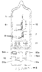
Fig. 1, a schemati.a side view of a halogen incandescent
lamp in a cementless base in accordance with the preferred
exemplary embodiment;
Fig. 2, a viaw of the holder part of the preferred
exemp~,ary embodiment from below;
Fig. 3, a cross section through the ginoh seal of the
halogen incandescent lamp of the preferred exemplary embodiment,
in which the sectional plane extends parallel to the narrow sides
of the pinch seal;
Fig. 4, a cross section through the holder part of Fig. 2;
Fig. 5, a side view, partly in section, of the lamp bulb of
the preferred exemplary embodiment.
~5 The halogen ~.ncandescent lamp in a cementless base of the
invention, in the preferred exemplary embodiment to be described
in further detail here, is a halogen incandescent lamp for use in
a motor vehicle headlight. Fig, 1 i.Ilustrates the structure of
this lamp. The halogen incandescent lamp of the invention has a
lamp bulb Z of hard gl~;ss, pinched tightly on one end. T'he pinch
-3-
b~:3lI~~: "J'1S~I~H13~ tl_~:~.;~ 1.~~a~ta9 h8 ~~- '~J-1Hd LJH'~SO:PJQ'n 0~~
bS:t~Z Z3~7-6Z

~~ 9~2~8
seal i0 of the lamp bulb ~. it clampingly fixed in a cup-shaped
holder part 2 of special steel. The ho7-der part z, together with
the base sheath 3 and the adjusting plate ~~ formed onto it, along
with the base block 5, forms the lamp base, The holder part 2 is
welded to the adjusting plate 4 via welding lugs 13 stamped aut of
the adjusting plate 4 and bent upward, Located inside the lamp
bulb 1 are two filaments 6, 7 which are each electrically
conductively conzxected to a respecti~re contact lug 9 via a total
of three power leads 8 that protrude from the pinch seal 30 and
are fused into a glass bead 11. one of the filaments S is
provided with a dimmer hood 12.
ThA parts o~ the lamp essential to a~.nderstandi.ng of the
invention are Shown in Figs. 2-5. Fig. 2 shows the holder part of
the halogen incandescent lamp according to the invention, seen
from below. Figs. 3 and 4 illustrate the cooperation of the pinch
seal 10 and the holder part 2. The holder part 2 has a stamped-
out recess 2p, in which the pinch seal 10 is clampingly fixed.
Six support tabs 21a, alb, 2~a, z2b, 23c~, ~3b are formed
onto the hvl~ier part Z and bent downward, that is, in the
direction of the aonta~ct lugs 9; these support tabs rest
clampingly against the broad sides of the pinch seal 1o, xrhich is
essentially rectangular in crass section. Four of the support
tabs 2ia, 22b, z~ao 23b are reinforced by means of beads, Which in
the horizontally extending portion lend them an approximately V-
shaped croJs section, while the two remaining support tabs 21a,
21b each have an approximately centrally located recess 24a, 24b.
These recesses 24d, 24b are each adapted, t~it.h an acCUr~lt$ fit, to
a respective guide rib 50a, 50b formed nnt~~ the nxc~ad sides of the
pinch seal 10. The guide ribs 50a, 50b extend in the longitudinal
direction, that is, parallel to the narrow sides of the pinch seal
-4-
SD:~lI~S hJOl~:~l3Hl~d H~l:hJt~ -~'a~~WS 5~ bt?+- L~-lid IJ~:~SCI:I,:L.;r1
fJC7 ~5:t'I ~~~7-6'm.

CA 02194288 2004-05-31
27813-59
10, and are located approximately centrally on the broad
sides of the pinch seal 10. To both sides of the guide ribs
50a, 50b, there is one respective luglike protrusion 51a,
52a, 51b, 52b each, which are likewise formed onto the pinch
seal 10. The upper end of these luglike protuberances 51a,
52a, 51b, 52b, together with the free ends of the support
tabs 21a, 21b, forms a detent closure. The pinch seal 10 is
tapered in graduated fashion toward the bottom, or in other
words toward the base. The thickness of the pinch seal 10,
below the luglike protrusions 51a, 52a, 51b, 52b, is
approximately 3.4 mm, while above the luglike protrusions
51a, 52a, 51b, 52b, it is approximately 3.8 mm. The narrow
sides of the pinch seal 10 are encompassed, without
touching, by circularly curved edges 25 of the recess 20 in
the holder part 2. The pinch seal 10 is also equipped with
four depth stops 53a, 54a, 53b, 54b, which are formed onto
the broad sides of the pinch seal 10 in the transitional
region to the lamp bulb 1. These depth stops 53a, 54a, 53b,
54b, after assembly, are seated on the support tabs 22a,
22b, 23a, 23b, which because of their beads protrude from
the surface of the cap of the holder part 2.
In accordance with this invention, there is
provided a halogen incandescent lamp in a cementless base
having a lamp bulb (1), which is provided with a pinch seal
(10), the pinch seal (10) having two broad sides and two
narrow sides, a base, which has a base sheath (3) and a
metal holder part (2) secured to the base sheath (3), the
holder part (2) having a recess (20) in which the pinch seal
(10) is clampingly fixed, support tabs (21a, 21b, 22a, 22b,
23a, 23b), formed onto the holder part (2), which rest
clampingly on the pinch seal (10), characterized in that the
pinch seal (10) is tapered iri the direction toward the base;
all the support tabs (21~a, 21b, 22a, 22b, 23a, 23b) formed
5

CA 02194288 2004-05-31
27813-59
onto the holder part (2) and acting upon the pinch seal (10)
are oriented toward the broad sides of the pinch seal (10);
the narrow sides of the pinch seal (10) are located spaced
apart from the holder part.(2) in the recess (20).
5a

Representative Drawing
A single figure which represents the drawing illustrating the invention.
Administrative Status

2024-08-01:As part of the Next Generation Patents (NGP) transition, the Canadian Patents Database (CPD) now contains a more detailed Event History, which replicates the Event Log of our new back-office solution.

Please note that "Inactive:" events refers to events no longer in use in our new back-office solution.

For a clearer understanding of the status of the application/patent presented on this page, the site Disclaimer , as well as the definitions for Patent , Event History , Maintenance Fee  and Payment History  should be consulted.

Event History

Description Date
Time Limit for Reversal Expired 2014-07-29
Letter Sent 2013-07-29
Inactive: IPC from MCD 2006-03-12
Grant by Issuance 2004-10-26
Inactive: Cover page published 2004-10-25
Pre-grant 2004-08-03
Inactive: Final fee received 2004-08-03
Notice of Allowance is Issued 2004-07-07
4 2004-07-07
Letter Sent 2004-07-07
Inactive: Approved for allowance (AFA) 2004-06-29
Amendment Received - Voluntary Amendment 2004-05-31
Inactive: S.30(2) Rules - Examiner requisition 2003-12-01
Inactive: Application prosecuted on TS as of Log entry date 2002-05-10
Letter Sent 2002-05-10
Inactive: Status info is complete as of Log entry date 2002-05-10
All Requirements for Examination Determined Compliant 2002-03-12
Request for Examination Requirements Determined Compliant 2002-03-12
National Entry Requirements Determined Compliant 1997-01-02
Application Published (Open to Public Inspection) 1996-02-22

Abandonment History

There is no abandonment history.

Maintenance Fee

The last payment was received on 2004-06-10

Note : If the full payment has not been received on or before the date indicated, a further fee may be required which may be one of the following

  • the reinstatement fee;
  • the late payment fee; or
  • additional fee to reverse deemed expiry.

Patent fees are adjusted on the 1st of January every year. The amounts above are the current amounts if received by December 31 of the current year.
Please refer to the CIPO Patent Fees web page to see all current fee amounts.

Owners on Record

Note: Records showing the ownership history in alphabetical order.

Current Owners on Record
PATENT-TREUHAND-GESELLSCHAFT FUER ELEKTRISCHE GLUEHLAMPEN MBH
Past Owners on Record
GERHARD BEHR
HERMANN STEINER
PETER HELBIG
Past Owners that do not appear in the "Owners on Record" listing will appear in other documentation within the application.
Documents

To view selected files, please enter reCAPTCHA code :


To view images, click a link in the Document Description column (Temporarily unavailable). To download the documents, select one or more checkboxes in the first column and then click the "Download Selected in PDF format (Zip Archive)" or the "Download Selected as Single PDF" button.

List of published and non-published patent-specific documents on the CPD .

If you have any difficulty accessing content, you can call the Client Service Centre at 1-866-997-1936 or send them an e-mail at CIPO Client Service Centre.


Document
Description 
Date
(yyyy-mm-dd) 
Number of pages   Size of Image (KB) 
Representative drawing 1997-11-16 1 10
Representative drawing 2003-11-30 1 9
Description 1995-07-26 5 221
Claims 1995-07-26 3 74
Drawings 1995-07-26 4 57
Cover Page 1995-07-26 1 21
Abstract 1995-07-26 1 27
Cover Page 1998-06-15 1 21
Description 2004-05-30 7 246
Claims 2004-05-30 3 71
Abstract 2004-07-06 1 27
Cover Page 2004-09-26 1 44
Reminder - Request for Examination 2002-03-27 1 119
Acknowledgement of Request for Examination 2002-05-09 1 179
Commissioner's Notice - Application Found Allowable 2004-07-06 1 162
Maintenance Fee Notice 2013-09-08 1 170
PCT 1997-08-14 5 159
PCT 1997-01-01 17 1,018
Correspondence 2004-08-02 1 33