Note: Descriptions are shown in the official language in which they were submitted.
2194588
WO 96138011 PCTYUS96103234
A METHOD FOR ASSIGNING SUBSCRIBERS
' BETWEEN NARROWBEAM SECTORS
Field of the Invention
This invention relates in general to communication
systems and, in particular, to a method of assigning a
subscriber's channel in a communications system.
a
Background of-the Invention
Cellular radio systems use base station radio
transceivers that are mounted,--typically on buildings or
on towers, to supply radio signals in their service
areas. In the classical analog systems, and in most
digital systems, a number of communications channels
having separate frequencies are used at each base
station, and these channels are reused at other base
stations that are spaced apart-by a minimum reuse
distaiice~ -To improve the efficiency of this reuse,
sectorized antennas are used to divide a- cell into 3 or
more sectors. By dividing the cell in this way, the
typical analog cellular-system can reduce its reuse
pattern from 12 cells in a cluster down to 7 cells per
cluster a-cluster being the number of cells with unique
fraquency7channel sets before xeuse is allowed. Thus,
by reducing the cluster size, more channels are
available at each cell, which yields-an improvement in
capacity.
. However, by dividing an omni pattern into a
sectored pattern, the transmit and receive antennas in a
given sector will only see a fraction of the sector.
Because of this,-the frequency-assignments must be
divided among the sectors. In other words, given
sectors 1, 2 and 3, the channels in sector 1 cannot, in
WO 96/38011 ~ ~ PCTIUS96103234
general, be used to cover sectors 2 or 3 since the
antennas point in different directions. Thus, there are'
now separate frequency groups for each sector if the
cell is sectorized_
FIG. 1 is-a prior art table of the Erlang B
distribution_ This is given here as background
information describing the effect of subdividing the
typical 3 to 6 sector base stations into a much larger
number of sectors. Typically for AMPS (Advanced Mobile
Phone-Service) cellular, a 3 sector 7-cell/cluster-
system could be assumed to have up-to19-channels per
sector with an evenly distributed-frequency assignment
plan. By adding additional-sectors, the-number of =
frequencies per sector generally goes down, even with
the cluster size being reduced. For a 6 sector 4-
celllcluster system, the number of-channels is reduced
to 16 per sector_ .Since there arecurrently-proposals
suggesting numbers of sectors up to 24 per cell, the
number of channels per sector will be significantly less
when they are equally divided as in a standar3 reuse
plan. FIG 1 shows the effect of having fewer servers in
a channel set~The result is a loss in trunking
efficiency, i_e., the average number of -servers that can
be supported decreases faster than the number of
channels.
FIG. 2 is a prior artdiagram illustrating a
standard 3 sector pattern-for a base station coverage
area-5 in which each sectors 10, 20, 30 are each served
by a 120 degree antQnna-pattern lT; 21~-31. These -
sectors 10, 2D, 30 are typically implemented by using
three separate antennas mounted on a building or totaer.
WO 96/38011
2 1 9 't
8 8 PCT/US96103234
,
_ 3 -
The actual capacity at each cell or sector, if the
' cell is divided into sectors, is a function of the
number offrequencies that are available in each
' frequency group. Since user traffic is not a uniform
5 process, i.e., users tend to arrive in a manner typical
of a Poisson process, and with~.exponential call
durations, the capacity is normally specified as an
Erlang B capacity at a given blocking rate. For
example, if a there were 29 frequencies available in
a
given sector, then according to the Erlang B table, an
average of 12.5 users can be served and this will give
a
blocking rate-of 2~, which means that 2~ of the time,
more than 19 users will try to obtain service. Thus,
a
channel set of 19 .frequencies would support 12.5 erlangs
IS of traffic at the given grade of service (GOS) or
blocking percentage.
Sectorization typically improves the range and
capacity of a cell--the range due to the added antenna
gain that is inherent with sectorized antennas, and the
capacity due to improvements in reuse. Therefore, it
should be of benefit to- increase the number of sectors
within a cell to some very large number. The typical
numbers-of sectors used in the world today are 3 to 6.
The problem with using more than 6 sectors, however,
is
the effect of dividing the frequency group into smaller
and smaller groups. It is typically desirable to keep
a
small, say 3-sector, group-of frecauencies, while being
able to switch the frequencies-within this group for
use
via a narrower beam within this channel set. However
this would require an enormous-amount of hardware to
switch say 20 frequencies to any number of beams within
a 12-0- degree sector. Thus it would be desirable to
simply divide-the frequency group into the number of
beams that are to be supported. This produces a
CA 02194588 1999-10-18
4
limitation in capacity however, since the number of erlangs decreases rapidly.
For
example, with 8 channels per beam, and a 2% GOS, only 2.5 erlangs is available
in
each beam.
There remains, therefore, a need for an improved method of assigning
channels to subscribers in a narrow beam communication system.
Summary of the Invention
According to one aspect of the invention a method for load-sharing between
a plurality of sectors of a base station is provided. The method includes the
steps of
monitoring a loading level for each sector of the plurality of sectors of the
base
station; in response to a first sector's loading level exceeding a
predetermined
threshold, selecting a first subscriber, communicating via the first sector,
that is
located closer to the vase station than a second subscriber communicating via
the
first sector; and; off loading the first subscriber to a further sector of the
base station
for communications with the first subscriber.
According to another aspect of the invention a method for load-sharing
between a plurality of sectors is provided. The method comprising the steps
measuring a level of communications channel utilization for each sector; in
response
to the level of a first sector of the narrowbeam sectors exceeding a
predetermined
threshold, selecting a first subscriber communication channel, communicating
via
the first sector, that is used by a subscriber located closer to the base
station than a
second subscriber communicating via the first sector; and; reassigning the
first
subscriber communication channel to a further sector of the plurality of
sectors for
communications with the first subscriber.
Brief Description of the Drawings
FIG. 1 is a prior art table of Erlang B loading for 2% blocking;
FIG. 2 is a diagram illustrating a typical prior art 3 sector antenna pattern
for
a base site coverage area;
CA 02194588 1999-10-18
4a
FIG. 3 is a flow diagram illustrating a first embodiment process according to
the invention; and
FIG. 4 is a diagram illustrating a narrow beam antenna pattern
implementation according to the first embodiment of the invention.
Detailed Description
These and other problems are met by the improved method of the present
invention. In a first embodiment of the invention, the apparent capacity of a
sector is
improved by dynamically off loading users who are sufficiently close to the
base
when the loading of the sector is close to its peak capacity. Thus, when the
sector is
sufficiently full, e.g., being within some predetermined number of users from
a
maximum, or at the
WO 96!38011 ~-~ ~ ~ 5 8 8 p~~7g96/03234
_ 5 _
maximum, the users being served are identified as to
' their potential to be served from another sector which
is more lightly loaded. This-results in more averaging
and less peaking in the channel usage within a group of
sectors, i.e., load sharing, thus holding off the point
at which blocking occurs within a given sector. This in
turn advantageously increases the capacity that the cell
can sexve_
This process is more difficult to implement with a
standard 3 sector pattern for users that are further
away since the antennas point at such dramatically
different (obtuse) angles. The closest users would
benefit from very low path losses due to their short
distance to the base, and the signal propagation effect
of local scattering which will enhance the path to an
adjacent sector due to reflections and diffractions
produced-by nearby clutter,- However,-bases having
numerous narrow beams, being overlapping beams and whose
angle between sectors is smaller, the Local scattering
required-to couple a signal into adjacent sectors is
minimal. Also, typical environments will exhibit
sufficient local scattering to provide a sufficiently
good signal path from up to several sectors, depending
on their angles with respect to the-subscriber. Users
that are close to-the base are--more likely to have paths
into adjoining sectors -that are sufficiently good, thus
permitting users to be reassigned to those sectors. Far
away users, near the edge of the cell, will have Less
overall path margin Left, and will be operating at near
the limit of the system gain_
Therefore, it is typically desirable, according to
this first embodiment of the invention, to select the
.closer users for off loading onto adjacent sectors when
WO 96/38011 219 4 5 ~ ~ p~'/[7596103Z34
- -6 -
the first sector is near its capacity limit. The
identification of a close user can be made based onany '
convenient measure, such as power control level, the
amount the subscriber is powered down, (in some digital '
systems) a timing advance used tQ measure the distance
based-on time of flight of ~he radio-propagation between
base and subscriber, etc. The power control method is
discussed below as part of the first embodiment since it
currently appears to be the most widely usedmethod
which should work with nearly every type of cellular=
system.
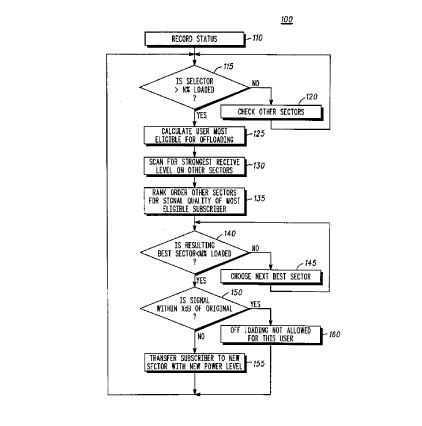
Turning now to FIG_ 3,--generally designated 100, a
flow diagram illustrating a-process accordingto a
preferred first embodiment of the present invention is
shown. The flow chart begins at block 110 where the
communications channel utilization for each narrow beam
sector at the base station is monitored and usage
statistics are recorded (e.g., as subscribercall or
channel usage changes). Such statistics are preferably
a loading level (e. g., number of. users divided by total
channels, or number of channels not in use), but can
include any loading-measure, e_g., periodic channel-
usage such as percentage of-frame occupancy (as in an E-
TDMA (enhanced time divisior~ multiple access) system),
adaptive measures etc_--Block 115_is-then preferably
executed which identifies a sector which is nearly
loaded, e_g., there are very few channels available for
new calls. If the sector is not loaded pas t a
predetermined loading threshold, block 120 is-executed
which looks at the next sector.
Once-a sector is loaded beyond the predetermined
threshold, the current users being served by-that sector
are analyzed in block-125-to determine the most eligible -
2194588
W0 96138011 PCfIUS96I03234
user (or subscriber communication channel) to be off-
loaded/reassigned onto another sector. The criterion
to
specify the most eligible user is preferably each user's
power setting,- although as noted above, any suitable
off-loading quality measure (or reassignment quality
measure) for transfer (e.g., hand-off or switching) to
anothersector maybe used. Users with the lowest power
setting are preferably selected here since such are the
users that are typically close to the base station. In
cellular radio systems, there are typically a number
of
power settings for a subscriber's transmit power level,
e.g., each being a given number of dB from the next
setting.--By determining the subscribers communicating
via the sector and picking the users) with the highest
power setting, the closest users) to the base station
are most likely selected. An additional selection
criterion that can be-used is the amount of time that
the subscriber has spent abovea given power level.
This further divides. the groupinto-users who have been
close for ahe longest amount of time.
The resulting quality measure, or Q-factor, can
thus be specified as Q -- A*PL .r H*T f C, where A &
B are
scaling coefficients that canbe adjusted by the
designer, PL is the power level of -the signal received
at the base station that is adjusted for the transmit
power setting of the subscriber unit, and T is the time
that the subscriber has been set t~ a giuen power
setting (thus indicating its consistency of operation).
C is a constant used to scale.the quantity into the
proper range. As an example of how the Q factor is
used, consider a case where the subscriber power levels
vary from 0-9 in integer values, with 9 being the
strongest. Assume also that B=0.2 for T<lOs (seconds),
and B=2.0for.T>lOs.(so that the quantity B*T ranges
2194588
WO 96f38011 PCTIUS96103234
_ g -
from 0-2 and stays at 2 for T larger than 10 seconds).
In this case, Q will range from 0-11 over a7.1 possible
ranges, with C=0. Thus, the power level is the larger
contributor to the Q factor; but the-time adds a smaller
variation to the total quantity. As an-alternative
method,-both the signal level and-the time the user has
been above a signal level-threshold could bespecified
separately with two different parameters. This would
not change the operation ofthe embodiment, but will
give the user--a somQwhat different set of parameters to
adjust.
Again, a skilled artisan will appreciate that a
variety of other -factors can be used to_specify the
quality measure, and changing the constituent factoYS,
or adding additional parameters, is still within--the
scope of the inventive process for evaluating a
subscriber as aligihle for selection for off-,
loading/hand-off_ -
Once the most eligible user is chosen, e.g., based
on the- Q-factor, scann.irig receivers for each of a group-
of-sectors at the base station are preferably used-to
scan for the selected user to obtain a reading of its
receive signal quality, e.g., its power-level in a _
received signal, optionally along with an identifying
tone, or digital word. -This is accomplished in block
130 which will typically include the proper averaging
intervals in order to.average out the fast fading -
(Rayleigh) fluctuations to obtain an estimate of the
local mean power level. -The group can be predetermined
as the n -closest/neighboring sectors (and searing
antenna's), all serving antennas from the source panel as
the loaded sector, a17. sectors of the..cell, or any other
convenient means. Black 13S orders the resulting
2194588
WO 96138011 PCTIUS96I03234
_ g _
readings for further processing in block 140, which
compares the ordered list to-achannel loading threshold
for each sector. If the best sector is not below a
predetermined loading threshold, block 145 selects the-
y next sector on the ordered list (i.e., having the next-
greatest quality measure) for testing in block 140.
After a sector is found that passes-the predetermined
loading threshold, block 150is preferably executed. In
this block, the signal levelis tested and compared with
the level indicated by the quality measure which was
determined in block 125. If the difference of these two
is within a given number ofdB, then the subscriber unit
is preferably transferred.to- a new server- (e.g., a
transceiver port) on a different-sector, and the power
level_is--set-at an appropriate value for operation on
this new server. Alternatively, the same server is
retained while switching it to the new serving sector,
optionally at a new frequency. After completing block
155, the process returns to the beginning. If the
result of block 150_is.negative, then the user is not
allowed to be switched since the amount of degradation
is considered too large based on the threshold of block
150_ Preferably block 150 is defined as a function of
the signal level, with different amounts of signal
degradation being allowed based on the starting level.
Thus, ifthe signal were strong before the transfer
attempt, then more signal degradation would be allowed;
however, if the signal level was weaker, then less
degradation would be allowed. A minimum signal level
floor may also be specified in this way.
FIG. 4 is a diagram illustrating a cell 400 with a
number of narrow-beam sectors in which the present
invention can be used. In this case, there are 24
narrow-beam sectors, generated by three panel antennas,
W0 96138011 PCTIUS96/0323J
- 10 -
each with 8 beams (e. g., 401-408 in a 120 degree
coverage area radiated from one panel) of 15-degree beam '
width each.
Therefore, it will be apparent to one skilled in
the art-that there has been-provided in-accordance with
the invention, a method for reassigning subscribers--from
a loaded narrowbeam sector that fully satisfies the
objectives, aims, and advantages set forth above.
4~lhile the invention has been described in
conjunction with specific.embodiments thereof, it is
evident that many alterations, modifications, and
variations will be apparent-to those skilled=in the art
in light of the foregoing description. For example the
invention is not limited in applicationto just cellular
communication-systems, but also applies to other types
of communication systems employing narrowbeam. antennas.
Accordingly, the invention is intended to embrace all
such alterations, modifications, and variations within
the spirit and scope of the appended claims.