Note: Descriptions are shown in the official language in which they were submitted.
2194613
METHOD AND APPARATUS FOR JOINING AND SUPPLYING
SEPARATED DOUGH BLOCKS
Background of Invention
1. Field of Invention
This invention relates to a method and an apparatus for joining separated
dough blocks to each other, and supplying a continuous sheet of dough.
Especially, this invention relates to a method and apparatus for joining a
following kneaded dough block to another kneaded dough block that was
supplied before the following dough block was supplied, so as to join the gel
structures of these dough blocks to each other when a plurality of kneaded
dough blocks are supplied to a production line.
2. Prior Art
In a conventional apparatus, a dough sheet is made of a kneaded dough block,
and then parts of the sheet are cut away from the dough sheet for production.
Each dough sheet has a volume corresponding to the volume of the kneaded
dough block supplied for each supplying operation of materials. The entire
dough sheet is in one production lot, or each part of the dough sheet is in a
production lot. When one dough sheet is in a production lot, time is lost
between the adjacent dough sheets when they are fed by a conveyor. Also,
fragments remain after parts are cut away from the dough sheets for
production.
In a conventional apparatus, if necessary dough sheets are joined to each
other by a manual operation. That is, a rear end of a dough sheet is piled on
CA 02194613 2001-O1-16
2
a front end of another dough sheet, and then the piled ends are manually
pressed so as to have them adhere to each other. There is no apparatus to
join dough sheets to each other. Thus, the operation must be done whenever
a following dough sheet is supplied, so that much manual work is needed to
perform the joining operation of dough sheets. In a production line of a
bread,
unmanned production is usually performed to make bread from dough sheets
that have the same conditions in their degree of composition and kneading,
because technology to make a thin dough sheet has been improved and is
now broadly used. However, when many kinds of breads that have several
shapes and additions, such as a filling, are made on the same production line,
much manual work is needed to join dough sheets whenever a following
dough sheet is supplied.
A unit of gel structure is formed for each dough block that is made by a
mixing
operation. Thus, for each lot, a gel structure in a dough block is separated
from that in another dough block, so that fragments of the dough blocks
remain after parts are cut away from them. There is no apparatus to
automatically join gel structures in dough blocks to each other.
Summary of Invention
This invention aims to overcome the disadvantages in the prior art. It
provides a method and apparatus to automatically join a following dough
block to a dough block previously provided, so that a very long and
continuous dough sheet is automatically made, and so that thus unmanned
production is achieved over 24 hours.
In an embodiment of the invention there is provided an apparatus for joining
a plurality of dough blocks to form a continuous dough sheet. The apparatus
comprises a plurality of rollers. The plurality of rollers includes a first
group
of rollers and a second group of rollers. The first group of rollers includes
a
first uppermost roller and a first lowermost roller. The second group of
rollers
CA 02194613 2001-O1-16
2a
includes a second uppermost roller and a second lowermost roller. The first
and second uppermost rollers are located in a first horizontal tier and are
separated by a first horizontal gap. The first and second lowermost rollers
are
located in a second horizoni:al tier and are separated by a second horizontal
gap. The first horizontal gap is greater than the second horizontal gap. The
first group of rollers is rotated in a direction opposite the second group of
rollers, such that the dough blocks are impelled downward toward the second
horizontal gap. The rotational speeds of the first and second lowermost
rollers are the same as or less than those of the first and second uppermost
rollers. The apparatus further comprises means for moving at least one of the
first group of rollers and the second group of rollers alternately and
relatively
toward and away from each other, such that the first horizontal gap and the
second horizontal gap are continuously and repeatedly increased and
decreased. This movement alternately increases and decreases a pressure
applied to the dough blocks passing between the first group of rollers and the
second group of rollers such that the gel structures of the plurality dough
blocks passing between the first and second group of rollers are integrated
to form the continuously dough sheet.
In an embodiment of the invention there is provided an apparatus for joining
a plurality of dough blocks to form a continuous dough sheet. The apparatus
comprises a plurality of rollers. The plurality of rollers includes a first
group
of rollers and a second group of rollers. The first group of rollers includes
a
first uppermost roller and a first lowermost roller. The second group of
rollers
includes a second uppermost roller and a second lowermost roller. The first
and second uppermost rollers are located in a first horizontal tier and are
separated by a first horizontal gap. The first and second lowermost rollers
are
located in a second horizontal tier and are separated by a second horizontal
gap. The first horizontal gap is greater than the second horizontal gap. The
first group of rollers is rotated in a direction opposite the second group of
rollers, such that the dough blocks are impelled downward toward the second
CA 02194613 2001-O1-16
2b
horizontal gap. The rotational speeds of the first group of rollers differ
from
those ofthe second group of rollers. The apparatus further comprises means
for moving at least one of the first group of rollers and the second group of
rollers alternately and relatively toward and away from each other, such that
the first horizontal gap and the second horizontal gap are continuously and
repeatedly increased and decreased. This movement alternatively increases
and decreases a pressure applied to the dough blocks passing between the
first group of rollers and the second group of rollers such that the gel
structures of the plurality of dough blocks passing between the first and
second lowermost rollers are integrated to form the continuous dough sheet.
In an embodiment of the invention there is provided a method of joining a
plurality of dough blocks to form a continuous dough sheet. The method
comprises the steps of providing dough blocks between a plurality of rollers,
rotating a first group of rollers in a first direction while rotating a second
group
of rollers in a direction opposite to the first direction, and moving at least
one
of the first group of rollers and the second group of rollers alternately and
relatively toward and away from each other. The step of providing dough
blocks between a plurality of rollers comprises providing dough blocks
between a plurality of rollers that include a first group of rollers and a
second
group of rollers. The first group of rollers includes a first uppermost roller
and
a first lowermost roller. The second group of rollers includes a second
uppermost roller and a second lowermost roller. The first and second
uppermost rollers are located in a first horizontal tier and are separated by
a
first horizontal gap. The fir~;t and second lowermost rollers are located in a
second horizontal tier and are separated by a second horizontal gap. The
first horizontal gap is greater than the second horizontal gap. The step of
rotating the first group of rollers in a first direction while rotating the
second
group of rollers in a direction opposite to the first direction comprises
rotating
the first group of rollers in a first direction while rotating the second
group of
rollers in a direction opposite to the first direction, the rotational speeds
of the
CA 02194613 2001-O1-16
2c
first and second lowermost rollers being the same as or less than those of the
first and second uppermost rollers. The step of moving at least one of the
first
group of rollers and the second group of rollers alternately and relatively
toward and away from each other comprises moving at least one of the first
group of rollers and the second group of rollers alternately and relatively
toward and away from each other such that the first horizontal gap and the
second horizontal gap are continuously and repeatedly increased and
decreased, thereby alternately increasing and decreasing a pressure applied
to the dough blocks passing there between, such that the gel structures of the
plurality of dough blocks passing between the first and second rollers are
integrated to form the continuous dough sheet.
In an embodiment of the invention there is provided a method for joining a
plurality of dough blocks to form a continuous dough sheet. The method
comprises the steps of providing dough blocks between a plurality of rollers,
rotating the first group of rollers, and moving at least one of the first
group of
rollers and the second group of rollers. The step of providing dough blocks
between a plurality of rollers comprises providing dough blocks between a
plurality of rollers that include a first group of rollers and a second group
of
rollers. The first group of rollers includes a first uppermost roller and a
first
lowermost roller. The second group of rollers includes a second uppermost
roller and a second lowermost roller. The first and second uppermost rollers
are located in a first horizontal tier and are separated by a first horizontal
gap.
The first and second lowermost rollers are located in a second horizontal tier
and are separated by a second horizontal gap. The first horizontal gap is
greater than the second horizontal gap. The step of rotating the first group
of rollers comprises rotating the first group of rollers in a first direction
while
rotating the second group of hollers in a direction opposite to the first
direction,
wherein the rotational speeds of the first group of rollers differ from those
of
the second group of rollers. The step of moving at least one of the first
group
of rollers and the second group of rollers comprises moving at least one of
the
CA 02194613 2001-O1-16
2d
first group of rollers and the second group of rollers alternately and
relatively
toward and away from each other such that the first horizontal gap and the
second horizontal gap arE; continuously and repeatedly increased and
decreased, thereby alternately increasing and decreasing a pressure applied
to the dough blocks passing there between, such that the gel structures of the
plurality of dough blocks passing between the first and second rollers are
integrated to form the continuous dough sheet.
This invention allows gel structures of dough blocks to be automaticallyjoined
to each other. This invention also allows several kinds of breads to be
~1g4~13
produced during a non-stop production step. In a conventional apparatus
there are many production lots corresponding to the mixing operations of the
dough. This invention allows a continuous dough sheet corresponding to one
production lot to be made. Thus, this invention allows the segments of dough
sheets to be minimized. Also, this invention allows the time until a following
dough sheet is received to be minimized.
One object of this invention is to provide a method and apparatus for joining
dough blocks to each other. The apparatus comprises horizontally and
oppositely positioned pairs of rollers being provided in a plurality of tiers.
The rollers are rotatable and arranged such that the distances between the
upper roller pairs are sequentially greater than the distances between the
lower roller pairs. The distances between the roller pairs are increased or
decreased when dough blocks are supplied between the roller pairs, so that
the rollers provide pressure to the dough blocks or release pressure from the
dough blocks as the dough blocks are impelled below by the pressing and
releasing effects and the rotations of the rollers. Thus, the growth of gluten
and the joining of gel structures of the dough blocks are accelerated, and a
continuous belt-like dough sheet is made.
The method uses horizontally and oppositely positioned pairs of rollers being
provided in a plurality of tiers. The rollers are rotatable and arranged such
that the distances between the upper roller pairs are sequentially greater
than the distances between the lower roller pairs. The method comprises a
step for changing the distances between the roller pairs such that the
distances are increased or decreased when dough blocks are supplied between
the roller pairs, so that the rollers provide the pressure to and release the
pressure from the dough blocks as they are impelled below by the pressing
and releasing effects and the rotations of the rollers, whereby the growth of
2194613
gluten and the joining of gel structures of the dough blocks are accelerated,
and whereby a continuous belt-like dough sheet is made.
Brief Description of the Drawings
Fig. 1 is a schematic side view of a bread production apparatus that includes
an embodiment of an apparatus for joining dough blocks to each other
according to this invention.
Fig. 2 is an enlarged schematic side view of the embodiment of the apparatus
for joining dough blocks to each other as in Fig. 1.
Figs. 3 and 4 are schematic side views to explain operations of the
embodiment of the apparatus in Fig. 2.
Fig. 5 is a schematic side view of another embodiment of the apparatus for
joining dough blocks to each other.
Description of the Preferred Embodiment
Fig. 1 shows a bread-making apparatus that includes an apparatus 1 for
joining dough blocks to each other. A bowl 2 mixes and kneads materials to
make dough. Dough 4 is supplied from the bowl 2 on a conveyor or a dough
feeder 3. The dough feeder 3 feeds the dough, and then supplies it to the
joining apparatus 1 in response to~ signals from a sensor 21 (see Fig. 2). The
joining apparatus joins dough blocks to each other to provide a continuous and
long belt-like dough 7 from a bottom opening on a first conveyor 8. The
dough is not separated. The first conveyor 8 feeds the dough 7 to a dough-
extending apparatus 9. The extending apparatus 9 presses and extends the
2194613
dough 7 to make a dough sheet 10 that has a predetermined thickness and
width that are required to make desired breads. The dough-extending
apparatus 9 feeds the dough sheet 10 to a conveyor 11. A depositing
apparatus 12 is located above the conveyor 11 so as to supply a filling such
as
jam and meat, on the dough sheet 10. A cutting apparatus 13 is positioned
over the conveyor 11. It moves vertically such that the dough sheet 10 is cut
to pieces, each of which pieces has a desired length and width. Also, the
cutting apparatus 13 may provide desired shapes to the pieces. Then
resulting dough pieces 14 are continuously output from the cutting apparatus
13.
Fig. 2 is an enlarged view of a part of Fig. 1. A hopper 22 is positioned at
the
forward end of the dough feeder 3. Rotatable cutter blades 5 are positioned
at a bottom opening of the hopper 22. The joining apparatus 1 is located
under the opening of the hopper 22. A sensor 21 is positioned near an upper
opening of the joining apparatus 1, and senses whether dough in the joining
apparatus decreases to such an extent that the upper surface of the dough is
below a predetermined level in the joining apparatus 1. When the sensor 21
senses the surface of the dough in the joining apparatus 1 being below a
predetermined level, it outputs a signal, so that the dough feeder 3 is
operated
to feed the dough 4 into the hopper 22. Simultaneously the dough cutter
blades 5 rotate. When the dough 4 is supplied from the dough feeder 3 to the
hopper 22, a dough block 6 is cut out from the dough 4 by the blades 5 at the
bottom opening, which block thus has a certain volume. The dough block 6
falls into the joining apparatus 1. As a result, the dough 4 can be kept at a
predetermined level in the joining apparatus 1.
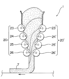
The joining apparatus includes a group 20 of rollers 23, 24, 25, and 26 and a
group 20' of rollers 23', 24', 25', and 26'. The cross-sectional shape of each
6
ZI 94613
roller is cylindrical. The row of rollers 23-26 and the row of rollers 23'-26'
are
arranged like a "V." Each roller of each group is opposite a corresponding
roller of the other group in a horizontal plane. Opposite roller pairs in
respective horizontal planes are rotated in opposite directions. Each roller
is
rotated by a suitable driving means (not shown). Each roller reciprocally
swings or reciprocally and linearly moves. Thus, the rollers in an opposite
roller pair can be moved to recede from or approach each other in a horizontal
plane, so that the gaps between them are increased or decreased. When the
opposite rollers approach each other, the dough between them is pressed by
them. When the opposite rollers recede from each other, the pressure is
removed from the dough.
The circumferential speeds of the lower rollers of the groups are lower than
those of the upper rollers of the groups. However, the circumferential speeds
of all of the rollers may be the same. Also, the speeds of the rollers of one
group may differ from those of the rollers of the other.
When the rollers in an opposite roller pair are moved to recede from and
approach each other, and they rotate at predetermined speeds, the dough is
repeatedly pressed or released from the pressure. As a result, the gluten in
the dough increases and the gel structures of the dough blocks are joined to
each other.
Fig. 3 shows the joining apparatus 1, in which the circumferential speeds of
the lower rollers of the groups are lower than those of the upper rollers.
For,
example, the speeds of the rollers 25, 25', and 26, 26' are lower than those
of
the rollers 23, 23' and 24, 24'. Parts of the surfaces of each dough block 6
that contact the upper rollers 23, 23', and 24, 24' are drawn below as they
rotate. Then, the parts and/or other parts of the surface of each dough block
2194613
7
6 that contact the lower rollers 25, 25', and 26, 26' are drawn to the bottom
of
the contacting apparatus as they rotate. Thus, the parts of the dough block 6
that contact the upper rollers flow faster than those that contact the lower
rollers.
However, parts of each dough block 6 in the middle between the opposite
roller pairs, which parts do not contact any roller, flow faster than the
parts
that contact the rollers. This is because the pressures caused by the opposite
roller pairs in each dough block 6 when they approach each other give force to
the dough blocks so that they move to the bottom opening, rather than the
dough blocks being drawn by the rotations of the rollers 23, 23', 24, 24', 25,
25',
26, and 26'. Thus, as shown in Fig. 3, parts of each dough block 6 that do not
contact the rollers and that are generally positioned at the middle between
each opposite roller pair flow faster than those that contact the rollers.
In detail, a surface of a dough block 6 is generally kept flat when the dough
block is supplied from the hopper 22 on the top dough block stacked in the
joining apparatus 1. As the dough block is drawn into the inside of the
joining apparatus, the surface of the dough block 6 that contacts the upper
surface of the lower dough block falls at the mid-point between the opposite
roller pair towards the inside of the lower dough block to be shaped as a V-
shaped layer. This V-shaped layer is gradually elongated below, so that the
surfaces of adjacent dough blocks that contact each other are increased.
Then, the layer extends longitudinally. Simultaneously, the roller pairs
move to approach, and recede from, each other, to press the dough block and
release the pressure from the dough block, so that the contacted surfaces are
vibrated by the motions of the rollers. As a result, the adhesion between the
contacted surfaces of the adjacent dough blocks is increased. Also, the
receding and approaching movements of the rollers function as a tapping
219~61~
motion on the dough blocks, resulting in generating a thixotropy effect. Thus,
the ffowage of the dough is increased and the joining of the gluten in the
dough is accelerated. Then, the joining apparatus 1 supplies a continuous
and belt-like dough sheet 7 to the first conveyor 8.
Fig. 4 shows the joining apparatus 1, in which the circumferential speeds of
the rollers of one group differ from those of the rollers of the other group.
That is, the circumferential speeds of the rollers 23, 24, 25, and 26 of the
group 20 are faster than those of the rollers 23', 24', 25', and 26' of the
group
20'. As a result, as shown in this figure, the parts of each dough block 6
that
contact the rollers 23, 24, 25, and 26 are drawn down faster by these rollers
than the parts of each dough block 6 that contact the rollers 23', 24', 25',
and
26'. Thus, each separated dough block 6 is modified to long continuous dough
layers. The receding and approaching movements of the rollers from and to
the dough layers are carried out so that adhesion of the dough is increased.
Then, the joining apparatus 1 supplies a continuous and belt-like dough sheet
7 to the first conveyor 8.
Fig. 5 shows another embodiment, namely, 1', of the joining apparatus 1 as in
Fig. 1. It includes a group 50 of rollers 51, 52, 53, and 54 and the group 20'
of
the rollers 23', 24', 25', and 26'. The cross-sectional shape of each roller
of the
group 20' is hexagonal. These hexagonal rollers impel the dough more
strongly than do the cylindrical rollers, so that each separated dough block 6
is modified more effectively to long continuous dough layers along the
longitudinal direction of the flow of the dough. The long continuous dough
layers extending in the longitudinal direction of the flow of the dough have
wide contacting areas to contact each other. Thus, the thixotropy effect is
caused, resulting in the unity of the gel structures of the dough layers.
21 ~4~13
Polygonal rollers may be used for the sectional shape of the rollers. Also,
polygonal rollers may be used for the upper rollers of the joining apparatus
in
Fig. 1, so that the same effects as is the case as in Fig. 4 can be generated.
In the above embodiments, either or both of the group 20' of the rollers 23',
24',
25', and 26' and the group 20 of the rollers 23, 24, 25, and 26 or either or
both
of the group 20' of the rollers 23', 24', 25', and 26' and the group 50 of
rollers 51,
52, 53, and 54 is/are reciprocally swung or linearly and reciprocally moved.
However, this invention is not limited to these configurations. For example,
the distances between the opposite roller pairs may be changed so that their
pressing movements are sequentially generated between them from above
downwards. Also, the distances between the opposite roller pairs may be
alternately changed in the vertical direction such that the pressing
movements between the opposite roller pairs are alternately effected in the
vertical direction.
By this invention gel structures in respective dough blocks can be joined to
each other by repeatedly providing pressing and vibrating operations to the
dough blocks, so that the dough blocks are deformed and piled upon each other
to form layers. Thus, a continuous belt-like dough web can be made.