Note: Descriptions are shown in the official language in which they were submitted.
~~9~s31
- 1 -
A F'OF;TAE~LE DEV I CE F(JF~ TFEAT I NG I NSECT ~ I TES AND THE L I t:E
The present invention relates to a portable device for-
trea.ting insect bites and the liE::e.
J
It is Ernown that at the present time then-a is a wide
spread of many products and devices which are adapted
for treatment of mosquito, wasp and bee bitp~~ or even
more severe bites such as those produced by sr_orpions
1 « and the 1 i t::e, vi per-s ar other an i mal s.
In particular, there are many products based on ammonia,
commerci al i red ei ther i n the f orm of a cream or- i n the
form of a stick:, which however are scarsely able to
iJ soothe irritation caused by bites and, in addition, they
have effects limited in time.
L~esi de the products bri ef 1 y descrl bed a.bave, spre.adi nq
of devi ces has al so occurred whi ch are capabl a of
treating the bitten area by heating until ~~~-bci°C (in
this connection see document FFi-A-11'9s~96> , as wel l as
of devi ces capabl a of produci ng passage of a 104~~~-vol tag,=
direct current directly from a small str,r~.ge bn.ttery to
the bitten area (see document lJS-4~827q-~'-F'EAF;SON> .
.y J
The above devi ces however are of 1 i ttl a f 1 e;; i bi 1 i ty
because a rather 1 ong per-i od of t i me i s requi red f or
reachi ng a good resin t i n terms of bi to tre~~.tment .
Ti? Ob vi ousl y due to the above 1 i mi t at i on , i t i s al so
i mpossi. bl a for several persons to taE::e advawtagr= of tine
devices in question sim~_iltaneously.
It i s al so to poi nt out that , i n any ca se, the
'J concerned devices need to be provided with a star-age
battery the cost of whi ch i. s not nec~l i c~ i b 7. ~~ and i n
addition periodical recharging of s~~m~_~ is to be carried
out by a user in order to ensure a correct operation of
2~946~~
the device itself.
A third type of known devices contemplates use of a.
structure capable of producing electric discharges of
very high voltage and very law current (see documents
US-O.~~Cr416-GUDER I AN; US-487.'; bi r9-CL I FFORD ; an d I T
M I 92U~oio 1 t'_a79-CAF'ONE ) .
These devices too however, have highlighted several
1r? drawbacks.
Fi rst of al 1 , the requi red c i rcui t f or carr-yi ng o~ ~.t
raising of the electric voltage has such an intrinsic
cost th at the overall cost of the devices becomes
greatly increased.
In addition, due to the intensity of the electric
discharge thus produced, use of these devices is only
just i f i ed when very ser i ous ca;>es are to b~~ tr-e~.ter~ ,
s~_tch as insect bites pr-od~_rced by wasps, bumble-bees or
score i an s or i n case of snake b i t es.
At all events, these devices are adapter] for a=.e on
adult_~ only because the electric discharge ha.s s~_i,=h an
?5 i ntensi ty that i t i s rather pai of ul by i i=sel f a.nri
therefore can be hardly usecl on children.
In addition, it will be recor~ni-~ed thai_ for these
devi ces too the use of starac~e batter-i es i s requi red ,
which will bring about an increase in prices and, as
al ready sai d above, the necessi ty to per-i od i ca.l 1. y
recharge or replace said storage batteries in order- to
enable a correct operation of the device.
Under this situation, the pr-esent invention aims at
providing a new portable device for treating insect
bites and the lit::e, capable of overcoming the above
mentioned drawbacks.
CA 02194631 2004-08-23
- 3 -
In particular, it is a fundamental object of the invention
to provide a device capable of operating in a correct manner
without requiring periodical rechargings.
In one aspect of the present invention a portable device for
treating insect bites comprising:
a holding casing (13);
voltage-generating means (101) defined by at least one
piezoelectric body (108) having opposite end faces;
drive means (102) presenting at least a spring striker
(107) housed in said casing and acting at least on an end
face of the piezoelectric body (108);
said drive means (102) presenting also a driving push
button (109) operatively connect to the spring striker (107)
and axially sliding in a sliding seat (109a) of the holding
casing (13), said driving push button (109) projecting at
least partly from a first end (103) of the casing (13);
first and second conductor means each of which is
electrically connected with a corresponding end face of the
piezoelectric body (108), said first and second conductor
means presenting respective terminal active portions (llla,
112a) operating in correspondence of a second end (104) of
the casing (13) axially opposed to the first end (103) of
the casing (13), said terminal active portions (llla, 112a)
being axially opposed to the push button (109).
Another object of the invention is to provide a device of
easy and ready setting so that its use may be very practical
and intuitive.
CA 02194631 2004-08-23
- 3a -
A further object of the invention is to provide a device of
simple structure and easy and cheap manufacture and above
all a device for the construction of which pieces that can
be easily found on the market are to be used.
Another important object of the invention is to provide a
device capable of producing electric discharges appropriate
for small-insect bites and therefore adapted for repeated
use on children too without involving any risks and without
causing too much worry or pain.
The foregoing and further objects that will become more
apparent in the progress of the present description are
substantially achieved by a device for treating insect bites
and the like, as disclosed in the appended claims.
Further features and advantages will best be understood from
the detailed description of some preferred embodiments of a
portable device in accordance with the present invention,
taken hereinafter by way of non-limiting example with
reference to the accompanying drawings, in which:
- Fig. 1 is a partial perspective view of one embodiment of
the device in question;
- Fig. 2 is a longitudinal view, partly in section, of the
representation taken in Fig. 1;
- Fig. 3 is a partly sectional longitudinal view of a second
embodiment of the device of the invention taken as a whole;
- Fig. 4 is a front view of the device shown in Fig. 3;
2194631
Fig. 5 is a partly sectional top view of the device
shown in Fig. T;
- Fig. 6 is a partly sectional langi.t~.ir_jinal view of
third embodiment of the device in question;
- Figs. 7a and 7b are two views at right angles to each
other and partly in section of a fourth embodiment of
the device in accordance with the invention;
- Fig. 8 is a partial front view of a detail to be
associ. aced wi th the devi ce i n q~ ~esti on;
ir-r - Fig. 9 is a sectional view ta~::en along line IX-IX in
Fig. ~3;
- Fig, irk is a view showing an alternative form of a
detail concerning the device shown in Figs. 1 to 5;
- Figs. 11 to 1' are perspective views of other
iJ embodi ments of the devi ce i n r~=f erence;
- Fi r~. 14 i s t:~ vi ew showi ng one of ' the =-st-m,l 1 w of ttne
devi ce i n Fi g . 1. ;
- Fi g. 1~ i s a vi ew showi ng one of the two shel 1 s
forming the device in Fig. l~ ; a.nd
ir-i _. Fi g . 16 i s a cross-secti oral vi ew tak:en al onr~_ 1 i ne
XVI-XVI in Fig. 11.
With reference to the drawings, a portable devir_e fcr
treating insect bites or- bites produced by other animals
has been generally identified by reference n!mer-a.l l~yi~.
In more detail and referring particularly to the
accompanyi ng drawi ngs, i t i s to note that Fi g ,. 1 and
show tloe inner components of on~= embodiment of the
device i.n ca~restion.
As vi. ewed frorn sai d f i gores, s~.~ch i nner- components
comprise voltage-generating means lril defin~=d by an
armature 1 preferably in the far-m of a stF,F,l pl~~.t~e~
which has a rectangular cavity ;? in the middle (see
Figs. and 7a) inside which a cylindric~:tl case _ m~~,de
of plastic material is housed; this Case has two
circular opposite ends that are open and hold two
219461
_
piezoelectric bodies in the form of ceramic cylinders 4
and 5. Each of said cylinders 4 and 5 is covered at its
outer end with a steel disc b, 7 and is separated from
the other cylinder by a brass disc 8. The portable
device comprises drive means 1«~ which is herein defined
by a manual contrivance consisting of a lever system 9
which, once operated, acts on the steel disc 7 to press
the two piezoelectric bodies. In this way, a voltage is
induced at the ends of the piezoelectric bodies so that
1« they deliver several electric discharges that ar-a picE:ed
up, through the brass disc 8, by a first conductor means
ic7 having one end welded at 1~ to said brass disc. A
second conductor means 11 has one end welded at 1~a to
the armature 1. The first and second conductor means 1ia
1~ and 11 therefore are true wire-1 i k::e conductors and have
active ends (electrodes) adapted to operate close to or
directly in contact with the user's area to be treated.
As shown in Figs. 3, 4 and ~, the inner- components
yc'_i bri ef l y descri bed above are hauled i n a casi ng 1 .:
consi st i ng of two shel 1 s 14 and 15 art i c~_~1 a.ted an each
other at a pivot pin F' close to a mouth 1b at which the
free ends of condur_tors 1r_~ and 11 converge. When
electric discharges are to be produced, grasping of the
casing 1~ is carried out by a user who preJses the two
shells 14, 1~ against eack~ other; said shells by
angul arl y movi ng cl ose to ear_p other- cause oiler-ati on of
lever 9a.
As shown in Fig. ~, the mouth ib which is entirely helcl
within one of said two shells, can take two positions at
the casi ng 1.'.: end . An annul ar e;: tensi on i 7 of mouth 1 b
can be f i tted wi th f orce i nta a f i rst or- a second
annular groove 18 formed in the two shells, while the
position of conductors 1c_~ and 11 remains unchanged. In
this way the distance of the two conductor ends from the
outer rim iC~ of mouth 16 can be of two or three
mi 1 1 i mFatres. As an al ternat i ve sol ~.~t i on , the mouth I6
2194fi31
- 6 -
may be provi ded to be mounted on ca.si ng 1.'. by
continuous adjustment system substantially enabling the
mouth to take an i ndef i ni to number of rel a.ti ve
positions with respect to the casing so that oper-ation
S of the device is conformed to the different requirements
of use.
Alternatively, Fig. 1 shows a steel armature 1 carrying
the cavity ~ and an e;,tension 11a in the form of an
1« elastic blade with a spherical end acting ~~.s a second
conductor.
Shown i n Fi g. b i s mother embod i ment of the devi r_e of
the invention in which the drive means icier is defined by
iJ a striking device cG~using an ele_r_tric disch.~a.rwge fr-om a
ceramic cylinder 5a (pie: aele~=tric body defining the
voltage-generating means) held within a plastic case Ta
covered at its ends with two steel discs 7a, 7b. A
stri k:i ng hammer 19 i s parti al 1 y hoc.rsed i. n a hol 1 ow
cyl i ndri cal cap ~c_i retai ned at the end of casi ng 1.'' i n
the device which comprises Gin opening having two
inclined walls ~~ and ~~ converging in the vicinity of a
pin ~4 p~.ssing thraugt~r the striking h:~.mmer- 19. The o~rter
end ~5 of the cylindrical cap acts as ~ push-button. In
addition, interposed between the cap end ~~ and the
stri(::ing hammer 19 is a spring ~b which can be in a
compressaed condi ti on wrren the pu=>h-butt=on i s pressed and
which p~_rshes the striking harnm~~r-. Immediately after
beginning of a compre'sian, the pin ?~ bea.rs against
shoulder ~7 integral with casing 1~:. S~_~.bseq~_~ently, a.s
compression goes on, the pin ~4 slides along the
inclined wall 2" reaching and going beyond the upper end
of shoulder ~7. At this point the striking hammer is
p<<shed with violence against the steel disc 7b and
produces del i very of an e7. ectri c di ~~ch=:~rg~~. T'he f i gore
al so shows conductor 1« wi th i is end pasi ti on~~d , by w<~y
of e;;ample, at ~.5 mm from the mouth rim iba and a strap
28 laid down on casing iT and connected to the ceramic
2194631
_,
cylinder 5a to work: as a ground strap.
For the sake of =~i mF?1 i ci ty, the f i g~_ire sloe=; not show a
spring the task: of which is to bring the striking hammer
back: to the starting position.
Figs. 7a and 7b show another embodiment in accordance
wi th the i n venti on i n whi ch the 1 ever system compr-i ses a
lever 9b and a push-button ~8 fastenr-ad to one end of
1s? sai d 1 ever. E~oth the 1 ever 9b ~~nd p~ ash-b~.itton ~~' are
made of a conductive material and define said idrive
means and also9 in this case, the secornd conductor
means.
1S ThFa 1 ever can press the pi e~ael. ectri c: c:yl i. nd:=r._ ~b hel. d
wi tln i n a case not shown , i n turn 1 acated i nv=i d~= the
cavity ? of arrrra.t~~.re 1. In this wa.y ~,~ =i. pF~rson appli.F=s
press! ~.re to push-b~_ttton ~sr wi th a f i ng,=r 9 a.n el ectri c
discharge is prad~_rced a.t tt~e end o~ conc:I~-~.ctr_ar 1c=?. Tt-m
electric discharg~= practically closew th~= elec_i_r-is
r_i rcui t def i ned bF~tween the f i n ger-, ty~F~ ~~~;er ' =~> bod y, thc,
application point of the devic a and the fir-si_ cr_,nd~?ctor-
(thi s i s obt ai ned by vi rtue of the cc~r?d~ ~,=t i ve
properti es of 1 ever 9b and push-b~ ~ttan y~Q~ .
~J
A1 so shown i s a mowtto 16b wh i ch i s to be cau sed to sl. i d~~
by friction within a cylindrical hr_»~sing .'~c-~ sr~ a~, tc~
vary the distance as the carlcluc'tor iii end fr-om tt-,.-_, o~-~.ter
mouth rim ci,
.T f ?
Figs. Ei and 9 ml so show a rrra~~i=h i~r_ cow.~c~nientl y
arranged so as to adjust the disi_~~r?cr_~ of one cand~_~ci_ar-
alone, far e:;a.mpl.e cands_~ctar- i.c~?q 4-~I-~.-r~r-F~.,_,.=; tl-ie.,
el.ect.ric
contact of condur_tar 11 with the skin ta.k:es pla.~=a a.lw~-~.yw
'S directly. Actually, even if position of mon.v~h 7.E~c within
the device end is varied, a copp~.ar tube .1 hau~~ed within
the central hole ~:~ of said mr_~?girth and e;;tending uritil
the outer ri m of the 1 utter i s al v.~ays i n contact wi th
219461
_8_
conductor 11 which is longitudinally fi;;ed, b~~re along
its end portion T and loose so as to always touch the
copper tube ~:1.
L_ac~ted aro~_rnd tt~e central hal a _ ~ i s a chamber
inside whir-_h conductor 1~r is ho,_rs~ad ~_rnrder t~r~y ang,_ila.r
posi ti on of the hand-wheel .T4. F~osi t i on of mouth 1 br_
wi th i n the casi ng end (not shaven ) i s def i ned b y ma k: i ng
i t rotate by mez-~ns of the handwheel .~:q. i n ei ther-
is~ direction, so that the helical tooth may slide in a
corresponding helir_al groove (not ~:,hown). for-med at one
end of the devi ce casi ng .
Openings ~b on the front wall of the mamth 1bc enable
1~ the electric circuit between the first candu~=for iii, tl-,~
user's skin and the second conductor 11 to be closed.
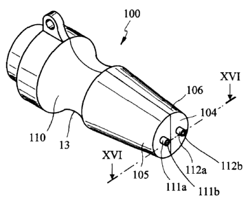
Finally, Figs. 11 to 1;~ sha4~~ another prefer-~snti~l
sol u.t i on i n ~e'coY"Clwtnce wi th th~~ i. nventi on i n whi r-rt-, the
ca si ng 1T i s provi ded t_a be def i neci by t~.~o shel 1 s l~l~
a.nd iirb to be mutu~711y engaged ~,.nd preferably qc4itc3
i dent i cal wi th er~.ch otlor~~r- sc~ th:~.t :a si ng 1 r~ moul d i s
requi red far- them r manuf ~~ct.ur-e. As v~. tewer_i f r-n,~ sa.i cl
figures, the drive means i=~ defined by ~~ spring strik:er._
~5 1i_y7 (of tfie =:~~rnF~ type ~w dc3=~crib~_-,d v~.ti.tln r-efer~er;~=a tr-1
tine
embodiment shown in Fig. b, far e:;a.rnple) acting on t~-,F~
voltage--gener~.~t~ing mean=~ ii~l consisting of
pie~aelectric body ic_is disposerj inside the casing.
'« As can be seen , the mutual 1 y-e~nga ged shel 1 s def i ne
sliding seat 1«9a for- the strit::e~r which is provid~=d with
a dr-ivi.ng push-button ic~g emerging at least partly- -Frorn
the casi ng so that i t can be acti voted by a. user-.
Advanta.geoc rsl y, the conform.~ati on of e_~ch steel 1 al so
defines an annul~-~r- engagement =~e.:-~ting llir disposed ~.~
longitudinally irrt.~_~rmedia~tE~a a.r~ec~ of 'the =,hells to enable
the devi ce to be easi 1 y handl ed 1 i E::e ~~ syr-i nge.
2194631
- 9 -
In this embodiment, the first and second conductor means
can be both def i ned by true condu,Tti ve wi res 1 1 1 , 1 1~
the ends 111x, 11~a of which partly em~rgF~ from, or- are
disposed substantially flush with an opera.tirzr_3 end face
1«4 of said casing (see in this connection Figs. 11 and
1~). It is to note that, in this case, terminal elements
111b , 11'b of substanti al 1 y cyl i ndr i cal conf ormat i on
(see Fig. 11) can be prefer ably aswocia.tcd with the
conductive wire ends.
1«
It should be pointed out that, c-~s on thre othar hand
clearly apparent from Fig. 1~, onea of the r-_ondur_tor-
means icy, 11 can be wool 1 y df~f i nFrd by one o-F sa.i d
terminal elements 111b, il~b. In more detail a
15 conci~_~ctive wire will be in this case r_.:onnF~ctF_ci a.~t onF_~
end with the piezoelectric body while, at the o~th,~r- end
11:'a, i t wi 1 1 be provi ded wi th ~.? t~~r ~mi rr.ul el ernent; thF~_
otter=r termi nal el ement 1 1?b of an ~?;; i al e;;ter-mi on
greater than the f ormF~r termi nal el ernent , wi 1 1 be
directly connected with a conductivF3 body i~ri al so
Eilectrically connected to the pi.F~~oeleci;ric horsy.
Alternatively, as shos<~n in Figva. iY a.nd 1~+, it is
provi sled that the f i r=~t r_=r_7nry_.rwtcr me=_~.ns a.l one be' def i nc~d
~5 by a true conducti ve wi re or- wi r-e-1 i k:ra r_-ond~ ~.c~tor 1 1 =:
havi ng one end i. 1Ta di. spos:;ed f 1 ush wi tlo ( _~,ee Fi g . 1'?
or- p~?rt i al 1 y einer-g i ng f rorn, or 1 oc.a.t erg bacE::w~?rW
rel at i ve to the end f ace of tyr'a c.:~ si nrWy (not. =shown >
' 9
whereas the second conductor mr?a.n ~ i s def i n~~d by th~~
:'~y push-button whi ch i s made of ~.?n el ectri ct.l 1 y c ondu,cti ve
materi al and el ectri cal l y connected to the p i e~oel ectri r-_
body.
In thi s case the ci rcui. t i s def i ned by -thF; f i r st
."5 conduc:tor means, the piezoelectric body, t17,= striker,
the push-button, the use~~r~'s body (thumb, h_vnd, a.r-m,
trunk:, area hit by a bite) and closes on the end 11a of
the first conductor means.
2194631
- 1 « __
Theref ore the el ectr-i c di ~~ch.~r-g~~ i. n thi s casF= i. s>>
directed trsnsversel.y of the are: submitted t~~ treatment
and it efficiently passes, thr-ough the poison or- other-
serum injected by the insect.
J
F'refera.bly, the ser_and conductor means compri ses c:~.sing
1T too which can be made of electrically conductive
material and i~; brought inter electric connection wit(-n
the striker or directly with the piezoelectr-is body on
1~? the opposite side from wl-per-a the first condor-_tor- mean=i
is connected. In this CcZSe, for insulation reasons, in
order to a~,roi d an el ectr i c di scharge d i reef 1 y b~_~twec~n
the end 1 1~'a of the f i rst candy ~.ctor- meari s a.nd the
casing, a. co~.~t:ing portion 1.14 of ins!.~lating rr~~.ter-i.a.l is
l~ advawtageo~ rsl y associ ated wi tl7 sa.i d c~a.wi rng 1.~: a.r~ d i
dlsfJOsed at ore casing end oppo<_~ed to the striE::Pr- or- ,a.t
s.~i d end f ace.
The invention achieves imporwtant aa.dv~;.a.nt~.ges.
Firstly, by adapting a very =~irnplr~ ama therefor-a
i ne:;pensi ve str!.rcture end wi th the use of tine
pie: oelectric body, a device hw been madr~ av~.il~?ble
which is cap~-~b7.e of treating insect bites and bite=_~
produced by other similar animals which can be l.s.=d
repeatedly, h~-~s a sub~~t.~.nti ~.11y infinite self-
coni~L~inedness and causes elec=tric dische?r-ges of few k:W
~7nd more preci sel y anti 1 a ma;; i ml.rm vt~l ue of a.bo! ~.t 1."; E::tl
(from a technical point of view disc'har-ges of higher-
-« vol Cage cool d be ~~.chi eyed, bu.t irhc_:~~y. wool d be f el i= to ~.
greater- e;; tent by the user3.
Ery virt~_tF~ of its simple str!.~.ct~nrw9 i=he device . in
quest i on can be ca.rr i ed by a a<~er wi th0~_t't occup y i ng too
'J much room, i s very 1 i r_~ht-i n--wr~i ght a.nci very ~:>ra.r_t i c:al. i
n
use, ~~bove al 1 wloen i t i s made i r~ tl-~e f or;n oa
striker, as shown in Figs. 11-1~.
2194631
- 11 -
In addition, particularly advw~tageo~_~s are those
configurations in which the first conductor means alone
is defined by a conductive wire and ha.s one end directly
acti ve on the user ' s s~::i n , vaherc~.~~~ the second can d~ ~ctor-
mean=~~ is defined, dependir~G an e~.ch indi.vir__p,:~,l r-_'~.se, b~y~
the casing, the striker, the push-b~_~tton, so that the
end of the first conductor means is ground-closed an the
user 's body thereby causi ng a transverse di. sci-~arge onto
the area to be treated.
1«
These embodiments ~-rre partic~~.l~-~rl y ad'J_a.fltageOL~'~ beca.~_~se,
due to the rel at i vel y 1 ow i nten si ty of the concerned
volt_tges (about 1' k:V) , it is pr a ferable for thr~
electric discharge to pass transversely s~~bstantia.lly
15 thra~.~gh the whal a C~r-ea hi t by a bi te.
T~'lt~ 1 nvent l an l a dl tea Eid'Jafltc'~gF?a~_ls l n l i=s (rla'~'t'
'=peyl't l ~;
L?.sper_t s o
Act~.~al 1 y, by the use of a canducti ve-m:~.ter-i a:..l ca.si ng , i n
the handgr i p area the chargr,= i nten s:i t.~ Per ~ ~.n i t s~_~r f ar_-e
passing thro!~gh the user's portion direr-_tly in canj_~.~.ct
with tl7e device is greatly red~_~ced. In a.dditian, in this
case, the use of the canting por-ti.on of ins~~lating
material is very ~.advantsge~~~~s; aet~_~ally, under
conditions, it ensures the substanti~-~.l impossibility a~
an electric discharge occurring between the c:,sing ~~nd
the end of the first conductive wirF~. On the contrary,
i t i s to note that wl-~en the devi r-_e i s operated i n vai n ,
due to the fact that the si ~ es of thF~ ca~.a.~ i ng pr~rti arf
can be establijh~~d in a precise manner-, clo'm_~r-e aL the
ei.re~.tit an tile ce-:vslrlg is obt~'~ined, which will bring
about protection of the pie~aelectrir-_ body that
atherwi se wool d undergo a dangera! ~s d i =~cha.rc~e at i t=>
~5 inside.
It i s al sa i mpartant to note th~.t ~-~ cer-ta.i n i mpar~tan.r._F:,
can be attached to the ~_~se of the ma!~th ta~saciatE~d at
219631
- 1~ -
its end with the casing which enables true distw~.nce of
one or both ends of the conduct i ve wi rev to be var i ed
relative to the body surface tn be treated. Thisy in
some r_ases, has proved to be advantageo~_~s for adj~~sting
the discharge intensity so as to adapt it both to the
bite nature and the user's particular sensitivity.
Obviously many modifications and v~.ria.tir-,ns can be made
to the invention as conceived, all of them falling
1« witl-iin the scr_7pe ref the appended cl~a.irr~a.