Note: Descriptions are shown in the official language in which they were submitted.
CA 02195002 1997-10-21
STEERING DRILL BIT WHILE DRILLING A BORE HOLE
BACKGROUND OF THE INVENTION
This invention relates to a method of drilling a bore hole using a
drill bit and more particularly to a method of steering the drill bit while
drilling a
bore hole to control the direction of drilling.
It is previously known that a substantially vertical well bore can be
turned with a short radius curved section into an inclined or horizontal well
bore by providing a drilling tool which includes a bend section defining a
transverse bend axis between a forward drill bit support portion and a
trailing
motor portion. The bend section of the drilling tool tends to steer the well
bore
so that it turns to a direction at right angles to a plane containing the bend
axis. One particular example of this technique is disclosed in my U.S. patent
5,265,687. In this patent I also proposed that the bore be continued in a
horizontal direction after the curved section is complete by adding shims to
the
underside of the drilling tool.
A method is disclosed in U.S. patent 5,215,151 (Smith et al) in
which the drilling of a bore hole is effected using continuous coiled tubing
which extends from a trailing end on a supply reel at the earth's surface to a
leading end within the well bore.
The drilling of well bores using continuous coiled tubing is known
conventionally and includes the supply of a drilling fluid which is pumped
into
the trailing end of the coiled tubing for transmitting the drilling fluid to
the
leading end of the tubing at the base of the well bore. At the base is
provided
a drilling tool which includes a drill bit rotatable relative to the drilling
tool, the
drill bit being driven by a motor powered by the flow of the drilling fluid
through the drilling tool.
CA 02195002 1997-10-21
2
It is also previously known that, when drilling a horizontal bore
section, the horizontal direction can be better maintained by slowly rotating
the
drilling tool with the bend section so that the bend section rotates about the
longitudinal axis of the drilling direction at a rate less than that of the
drill bit.
The above U.S. patent of Smith discloses a technique of steering
the drilling tool to vary the azimuth of the curved bore section by providing
an
orientation device as a part of the drilling tool. The drilling tool thus
comprises
an upper part fixed relative to the drill tubing and a lower part including
the drill
bit and the bend section. A control motor system is provided by which the
lower section can be rotated relative to the upper section in indexed steps of
controlled predetermined amounts in response to motive force provided from
the surface in the form of pulses in the drilling fluid.
A similar arrangement is disclosed in U.S. patent No. 5,311,952 of
Eddison et al which uses an indexing device that is actuated by mud pulses but
this in addition states that the reactive torque from the drill bit assists in
effecting the rotation in the indexing direction.
These arrangement are generally satisfactory and have achieved
some success but are relatively complex involving signaling from the surface
and relatively complex mechanical structures in the drilling tool. It is also
necessary to halt the drilling action and to lift the weight off the drill bit
during
the indexing step and therefore it is not possible to use this technique for
slowly rotating the drilling tool while the drilling continues.
More recently designs of slowly rotating down-hole motors are
currently being proposed which can also be commanded from the surface to
start and stop to control changes in direction. However these have the
disadvantages that it is difficult to convey power from the surface and also
it is
CA 02195002 2000-02-07
3
difficult to provide enough torque to turn the complete tool while drilling
without
putting too much torque on the coiled tubing, as this is susceptible to damage
if over
torqued.
It has also been proposed to steer the drilling tool by rotating the
injector about the axis of the drill string. This acts to rotate the tubing
which in turn
rotates the drilling tool to the required angle.
SUMMARY OF THE INVENTION
It is one object of the present invention, therefore, to provide an
improved drilling method which enables effective control of the drilling
direction of a
bore hole while avoiding the necessity for communicating significant power
from the
surface to the downhole control system and avoiding the possibility of
applying
excess torque to the drill string.
According to a first aspect of the invention there is provided a
method of drilling a bore hole in the earth comprising: providing a drill
string
having a trailing end at ground level and a leading end for insertion into the
bore hole; connecting a supply of drilling fluid to the trailing end for
pumping
the drilling fluid to the leading end; providing a drilling tool having an
elongate
tool body defining a longitudinal axis therealong, providing a motor mounted
on
the tool body to generate drive power, providing a drill bit mounted on the
tool
body at a leading end thereof for rotation of the drill bit in an angular
direction
relative to the tool body about the longitudinal axis in responsive to the
drive
power from the motor, and providing means forming a bend section in the tool
body defining a bend axis of the tool body transverse to the longitudinal axis
of
the tool body such said rotation of the drill bit tends to steer a
longitudinal
CA 02195002 1997-10-21
4
drilling direction of the tool body in a direction at an angle to a plane
containing
the bend axis and the longitudinal axis; connecting a trailing end of the
drilling
tool body to the leading end of the drill string so as to communicate drilling
fluid from the drill string to the tool body to cause rotation of the drill
bit; in
order to form a straight section of the bore hole, allowing counter-rotation
of
the tool body relative to the leading end of the drill string in an angular
direction opposite to the angular direction of the drill bit in response to
torque
generated at the drill bit so as to cause rotation of the tool body and the
transverse bend axis about the longitudinal axis, with motive force for the
counter-rotation being provided by the torque from the drill bit, and
controlling
the counter-rotation to be maintained during the formation of the straight
section at a rate less than that of the rotation of the drill bit; and, in
order to
steer the longitudinal drilling direction by forming a curved section of the
bore
hole, occasionally halting the counter-rotation to hold the bend axis at a
predetermined orientation.
Preferably the control means comprises a hydraulic pump system
which is connected between the drill string and the drilling tool so as to
cause
fluid flow around a closed loop to provide a resistance to the rotation
between
the drill string and the drilling tool. In this way only a controlled amount
of the
torque generated between the motor and the drill bit is used to effect the
counter-rotation while the remainder effects the normally required rotation
between the drill bit and the bore to effect the drilling action. This control
of
the torque limits the counter-rotation to a rate less than that of the drill
bit. In
addition the pump system includes a valve actuable from the surface to halt
the
fluid flow to lock up the counter-rotation thus holding the bend axis in a
specific orientation to effect a change in drilling direction.
A
CA 02195002 1997-10-21
While specifically disclosed herein as a hydraulic pump system, the
function of the control means can be effected by other arrangements including,
but not limited to a friction brake; a fluid coupling with a friction brake;
an
indexing system such as a ratchet or indexing pins which allow the counter-
s rotation to proceed at only a predetermined rate regardless of the magnitude
of
the torque; or any combination of these techniques.
According to a second aspect of the invention there is provided a
method of drilling a bore hole in the earth wherein the bore hole includes a
first
substantially straight portion extending from ground level to a first below
ground location and a curved portion extending from the first below ground
location to a second below ground location, the method comprising: providing a
drill string having a trailing end at ground level and a leading end for
insertion
into the bore hole; connecting a supply of drilling fluid to the trailing end
for
pumping the drilling fluid to the leading end; providing a drilling tool
having an
elongate tool body defining a longitudinal axis therealong, providing a motor
mounted on the tool body to generate drive power, providing a drill bit
mounted
on the tool body at a leading end thereof for rotation of the drill bit in an
angular direction relative to the tool body about the longitudinal axis in
responsive to the drive power from the motor, and providing means forming a
bend section in the tool body defining a bend axis of the tool body transverse
to the longitudinal axis of the tool body such said rotation of the drill bit
tends
to steer a longitudinal drilling direction of the tool body in a direction at
an
angle to a plane containing the bend axis and the longitudinal axis;
connecting
a trailing end of the drilling tool body to the leading end of the drill
string so as
to communicate drilling fluid from the drill string to the tool body to cause
rotation of the drill bit; in order to form a straight section of the bore
hole
CA 02195002 1997-10-21
6
extending from the second below ground location, causing counter-rotation of
the tool body relative to the leading end of the drill string in an angular
direction opposite to the angular direction of the drill bit so as to cause
rotation
of the tool body and the transverse bend axis about the longitudinal axis, and
providing control means for controlling the counter-rotation to be maintained
during the formation of the straight section at a rate that the
less than of
rotation of the drillbit; wherein the control means is in first
located the
substantially straightportion spaced downwardly from the surfaceand
ground
is interconnected through
to the tool body the
by a length of tubing
extending
curved section that the length of tubing counter-rotates tool
such with the
body relative to the drill string and relative to the of bore
curved section the
hole.
One embodiment of the invention will now be described in
conjunction with the accompanying drawings in which:
BRIEF DESCRIPTION OF THE DRAWINGS
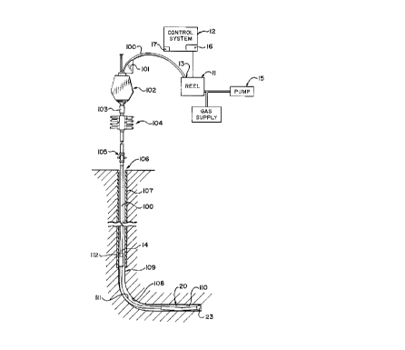
Figure 1 is a schematic side elevational view of a drilling system
including the ground level control system and the downhole drilling tool.
Figure 2 is a side elevational view of the down hole drilling tool
only of a system similar to that of Figure 1 in which the control device is
arranged immediately adjacent the tool body.
Figure 3 is a cross sectional view through the control device of
Figure 1 or Figure 2.
In the drawings like characters of reference indicate corresponding
parts in the different figures.
CA 02195002 2000-02-07
7
DETAILED DESCRIPTION
The arrangement of the present invention is based on my above U.S.
patent No. 5,265,687. In particular the down hole drilling tool as shown
schematically in Figure 1 is taken from the disclosure of the above patent. In
addition Figure 1 also includes the above ground construction which is shown
schematically for completeness.
The apparatus therefore includes a drill tubing which as shown can
comprise coiled tubing 100 supplied from a reel (not shown) over a guide arch
101.
From the arch 101, the tubing enters an injector schematically indicated at
102
which is again of a conventional nature and acts to grasp the tubing using
blocks
which frictionally engage the tubing and force the tubing longitudinally both
in the
downward or the upward direction for feeding and withdrawing the tubing into
the
well bore. The construction of the injector is well known and this also acts
to hold
the tubing against rotation in a twisting direction so that the tubing is fed
directly
longitudinal without any twisting about its axis. In one known arrangement of
the
injector the tubing is grasped by opposed blocks, each of which has a front
face of
semi-cylindrical shape so that together the blocks form the majority of a
cylinder
surrounding the tubing. A plurality of the blocks are then mounted in two rows
carried on a pair of opposed chains and movable thereby longitudinally of the
well
bore. The blocks are biased into engagement with the tubing by guide plates.
From the injector, the tubing passes into the well bore through a
stripper a blow out protector (BOP) a lubricator105 to the
103, 104 and well
head 106. The stripper, BOP and lubricatorare of well known
a and
conventionalnature and are therefore shownschematicallyand will not
only be
CA 02195002 1997-10-21
8
described in detail herein. In an arrangement wherein the well bore is an
existing producing well in which it is required to drill an extra horizontal
section
to increase production, the well includes an existing casing 107 in a
substantially vertical portion of the well at the well head 106.
My U.S. patent 5,265,687 describes the technique for drilling the
short radius curved section 108 at or adjacent a bottom end 109 of the
vertical
portion. The present invention is particularly concerned with a method for
controlling the drilling of a horizontal straight section 110 of the well bore
at
the remote end of the curved portion 108.
The system at ground level includes a reel 11 for the coiled tubing
100 so that the coil tubing has an upper end 13 attached to the reel and a
lower end 14 attached to the drilling tool generally indicated at 20. A
drilling
fluid pump 15 supplies drilling fluid into the upper end 13 of the coil tubing
at
the reel for transmitting the drilling fluid through the coil tubing to the
down
hole drilling tool 20. In addition at the ground level there is provided a
control
system 12 which includes a display 16 for receiving information from downhole
transducers and a control system including a valve control 17 for supplying
downhole control data to the drilling tool.
The downhole drilling tool 20 is shown in larger scale in Figure 2
and includes a conventional motor 22 which is preferably of the type driven by
the flowing drilling fluid for generating a rotational movement which is
communicated to the drill bit 23 for rotation of the drill bit in a bearing
section
23A about a longitudinal axis 24 of the drill bit. In the arrangement shown,
the
motor is attached to the bearing section of the drill bit by a knuckle 25
which
provides a shallow bend angle 26 between a longitudinal axis 27 of the motor
and the longitudinal axis 24 of the drill bit. This bend angle is obtained by
A
CA 02195002 1997-10-21
9
cranking the drill bit about a transverse axis 28 at right angles to the
longitudinal axis 24 and 27. In the position shown, therefore, the drill bit
will
have a tendency to drill upwardly that is in a direction generally at right
angles
to the transverse bend axis 28 and on the side of the longitudinal axis 24
opposite to the angle 26.
It is well known that a bent drilling tool of this type can be used to
drill horizontal bore holes 21 by slowly rotating the drilling tool including
the
motor and the drill bit about the longitudinal axis of the drill bit so that
the axis
28 gradually rotates about the axis 24. This gradual rotation of a bent
drilling
tool provides more accurate control over the horizontal orientation than would
simply providing a straight drilling tool and maintain that straight drilling
tool in
the fixed horizontal orientation.
It is further known, in the event that the drilling tool deviates from
the required direction, the direction of drilling can be controlled by halting
the
slow rotation of the drilling tool about the axis 24 and holding the bend axis
28
at a required orientation so as to direct the drill bit in the required
direction to
overcome the inaccuracy in the drilling. In this way the bend axis 28 can be
maintained stationary for sufficient period of time to regain the required
direction of drilling. A sensor unit is schematically indicated at 30 which is
used to detect the orientation of the drilling tool during drilling to detect
and
control deviations from the required direction drilling.
The sensor 30 is of conventional construction and accordingly
shown only schematically. The sensor 30 communicates through a
communication system 31 shown schematically as a cable passing through the
coil tubing for communicating information to the display 16.
CA 02195002 1997-10-21
It is further well known and readily apparent that the rotation of
the drill bit in engagement with a drill face of the hole to be drilled
generates
torque in the drilling tool tending to twist the coiled tubing. This torque
must
be resisted by the coil tubing in order to generate the rotation of the drill
bit
5 relative to the drill face.
The present invention is directed to the problem of providing a
motive force and control for effecting the relatively slow rotation of the
drilling
tool about the longitudinal axis of the drill bit. In the present invention,
therefore, there is provided an additional control device schematically
indicated
10 at 40 which is located between the drilling tool 20 and the coiled tubing
100.
In Figure 1, the control device 40 is located at or adjacent the
lower end of the vertical portion of the well and is connected to the drilling
tool
body by a length of tubing 111 which extends through the lowermost part of
the vertical portion and through the curved portion to the required position
of
the horizontal section. The length of the tubing 111 is selected so that the
control device remains in the vertical portion within the casing 107 while the
tool moves to drill the curved portion and the required length of the
horizontal
section.
In Figure 2, the arrangement is modified so that the control device
is located immediately at or adjacent the drilling tool.
The details of the control device are shown in Figure 3 wherein the
control device includes a downstream portion 41 and an upstream portion 42
with a downstream portion 41 connected to the drilling tool by conventional
connection systems and the upstream portion 42 is connected to the coil
tubing as schematically indicated at 14. The portion 41 is connected to the
portion 42 by a swivel coupling assembly 43 including an annular bearing 44
CA 02195002 1997-10-21
11
and a seal 45. The portions 41 and 42 thus form an annular interconnection
which allows rotation about the longitudinal axis 27 of the motor 22. In the
example shown both of the portions 41 and 42 comprise a cylindrical member
with an end of the portion 41 inside the adjacent end of the portion 42 so
that
the bearing and seal are located in the cylindrical area therebetween.
On the inside surface of the end 41 A of the portion 41 is provided
a ring gear 46 fixed to the end 41 A so as to be rotatable therewith. A pump
47 is mounted by a bracket 48 on the inside of the end 49 of the portion 42.
The pump carries a drive shaft 50 on which is mounted a pinion 51 rotatable in
the ring gear 46. Thus rotation between the portion 41 and 42 effects rotation
of the pinion relative to the ring gear so as to drive the pinion 51 and thus
to
drive the fluid pump 47.
The pump includes a closed circuit 52 so that output pressure
from the pump on a line 53 passes through the circuit 52 and returns to an
inlet 54 of the pump. The fluid circuit includes an orifice 55 which acts as a
restriction to flow thus providing a back pressure on the pump 47. The fluid
circuit further includes a control valve 56 which is operable to halt the flow
of
fluid through the circuit 52. The circuit further includes a top up reservoir
57
with a piston 58 and the spring 59 for supplying top up fluid into the circuit
should any leaks cause a loss in the fluid. A backcheck valve 60 prevents the
pressure in the circuit 52 from entering the reservoir 57 if reverse torque is
inadvertently applied for a short time.
The connection between the portions 41 and 42 through the
bearing 44 therefore provides effectively free rotation of the drilling tool
relative
to the drill string provided by the coil tubing. Rotation of the motor
therefore
will effect a driving force to the drill bit but that driving force will also
generate
A
CA 02195002 1997-10-21
12
a counter-rotation in the drilling tool caused by the torque between the drill
bit
and the drill face. As there is free rotation between the portions 41 and 42,
this counter-rotation will be taken up in the bearing connection therebetween
and will therefore normally allow this free counter rotation to prevent
rotation
of the drill bit.
In order to restrict this free rotation, therefore, the pump 47 and
the closed circuit 52 are provided which acts as a restriction on this free
rotation with that restriction being controlled or determined by the
resistance to
flow provided by the orifice 55. The orifice is selected therefore to provide
a
predetermined resistance to rotation at the connection between the portions 41
and 42 with that resistance to rotation being sufficient to accommodate a
portion of the torque generated by the drill bit so the drill bit rotates but
also
the motor rotates in counter rotation about the axis 27. The resistance to
flow
in the circuit 52 is further arranged so that the rate of rotation of the
motor
about the axis 27 is significantly slower than the rate of rotation of the
drill bit.
This arrangement can therefore be predetermined so that the required slow
rotation of the drilling tool about the axis 27 is obtained while the drill
bit
rotates more quickly to effect the drilling action. Normally with a
predetermined
loading on the drill bit and a predetermined rate of rotation of the drill
bit, the
required restriction to flow can be precalculated to obtain the required
relative
rotations of the drilling tool about the axis and the drill bit about its
axis. The
selection of a predetermined orifice in the circuit thus effectively sets a
maximum rate which is dependent upon the torque from the drill bit. The
orifice
can also be changed to vary the maximum rate.
In addition the valve 56 can be actuated through the control cable
31 so that the circuit 52 is fully closed thus preventing rotation of the pump
47
CA 02195002 1997-10-21
13
which is of the positive displacement type. In this way the pump acts to lock
the pinion on the gear wheel thus locking the portions 41 and 42 in fixed
position. When so fixed, the rotation of the drilling tool about the axis 27
is
halted and all of the rotation is effected through the drilling bit without
any
counter-rotation. The valve can be actuated at a required position of the bend
axis 28 so as to direct the tendency of the drill bit to turn in the required
direction to correct any steering errors.
The rotation of the drilling tool is therefore obtained by extracting
from the normal rotation of the drill bit a smaller portion of the torque to
provide a motive force for the counter-rotation. There is no necessity
therefore
for any supply of additional motive force from the surface, from battery power
or the like. Furthermore, the absorption of some of the torque to the drill
bit in
the counter-rotation reduces the torque on the drill string. With the drill
string
designed and manufactured to accommodate the maximum torque which can
be generated by the motor, the drill string can certainly accommodate the
reduced torque which is obtained as a portion of that torque is communicated
through the junction of the control device 40. There is little or no
possibility
therefore of over torquing the drill string thus avoiding the potential for
damage
which can be effected by conventional downhole drive motors.
As the rotation of the drilling tool is obtained as a counter-rotation
generated wholly by the torque from the drill bit, there is no necessity for
any
pulses to be supplied from the ground surface to control an indexing device.
The mud pressure can therefore be maintained constant and the mud flow rate
also remains constant so the drilling continues at a constant rate and at a
constant torque on the drill bit. In addition the rotation of the drilling
tool is at
a constant rate which provides the required proper control of the drilling
CA 02195002 1997-10-21
14
direction by smoothly rotating the drilling tool at the constant rate as
previously
described.
In the arrangement shown in Figure 1, the control device 40 is
located in the casing at the lower end of the vertical portion of the well
bore.
The control device is then connected to the drilling tool body itself by the
length of tubing 111. In effect, therefore, the drilling tool comprises the
control device, the length of tubing and the tool body itself. As previously
described, therefore, the lower part of the control device together with the
tool
body rotate within the well bore and this rotation is of course communicated
through and includes rotation of the tubing 111.
In drilling the horizontal section of the hole there is considerable
friction where the tubing goes through the curved portion of the hole which
dramatically reduces the penetration rate. For example, if the system is
drilling
with 3000 pounds pressure vertically downwardly on the drill string, there is
between 2000 pounds and 3500 pounds of friction to move the tubing through
the curved portion. It will be appreciated in this regard that the downward
pressure on the drill string applies a significant force pressing the tubing
111
against the outside curvature of the curved portion of the well. Because of
this
high and variable friction, it is impossible to keep a constant weight on the
bit.
Thus the bit can drill off completely so that there is no pressure on the
drill bit
in a situation where the friction exceeds the downward pressure on the drill
string. In this situation the drill string can then slip through the curved
section
to reapply some pressure at the bit. This variation in the pressure on the bit
from very little or no pressure up to a higher pressure which is less than the
vertical pressure on the drill string reduces the efficiency of the drilling
action.
In addition the variations in pressure on the drill bit of course vary the
torque
CA 02195002 2000-02-07
generated by the drill bit so that there is a tendency to vary the windup in
the drill
string.
This linear friction through the curved portion of the well bore can be
practically eliminated by continuous rotation of the tubing 111 through the
curved
5 bore section where the friction exists.
In order to provide a method of underbalanced drilling in which a gas
is carried through a portion of the drill string tubing and is released into
the well
bore at a position adjacent the drilling tool, in the present arrangement, gas
is
released at a discharge vent 112 immediately adjacent the control device 40.
This
10 therefore releases the gas at a position within the vertical portion of the
well bore
and within the casing 107. This arrangement avoids the possibility of erosion
of the
well bore in a situation where the fluid in the bore has an increased velocity
due to
the addition of the gas. The gas therefore is injected into the well bore at
the casing
without the possibility of erosion in view of the existence of the casing at
that
15 position and yet the supplying of the gas reduces the hydrostatic head of
the fluid
within the well bore to allow underbalanced drilling. In the curved and
horizontal
portions of the well bore which do not have any casing, the drilling fluid
consists
solely of the pure liquid so that the velocity of the liquid through the well
bore is
reduced or at a conventional level to avoid the detrimental effects of the
high
velocity fluid. The arrangement of Figure 1 is installed and operated using
the
following process. Firstly the bit and motor on the drilling tool are fed into
the hole
with a check valve within the drill string to prevent fluid from flowing up
CA 02195002 1997-10-21
16
the tubing from the producing well. This part of the tubing which constitutes
the tubing 111 is of a length sufficient to drill the desired distance
horizontal as
well as to pass through the curved portion and into the vertical portion of
the
well. This portion of the tubing can be run from the main tubing supply reel
11
or from a separate or auxiliary reel if large diameter tubing is used for deep
well
drilling. The tubing 111 is then held by the slips in the BOP 104 and is
released by the injector 102. The injector can then be lifted hydraulically by
the lift system (not shown) to allow enough room to attach the control device
40 and the discharge device 112. The coil tubing 100 from the reel 11 is then
brought through the injector and attached to the top of the control device 40.
The tubing 100 is then fed into the hole to move the tool to the bottom of the
hole to commence drilling of the curved portion. This procedure can easily be
done with available equipment while there is pressure in the existing
production
well.
The control device as shown in the present arrangement includes
the motor which restricts the counter-rotation of the control device to a
predetermined rate. However it will be appreciated that in alternative
arrangements the motor can be replaced by other devices which act to restrict
the rate of counter-rotation to a predetermined rate. Such arrangements can
include elements which utilize friction as the force for restricting the
rotation or
can use arrangements which utilize a stepping action. The basic concept is
that the control device allows the counter-rotation to occur in response to
the
torque from the drill bit but then controls that counter-rotation to a
predetermined substantially constant rate slower than that of the drill bit or
to
stop that counter-rotation when desired. For example, the rotation can be
~s
CA 02195002 1997-10-21
17
restricted by a friction brake which is controlled by an arrangement similar
to
that of the anti-lock brakes of a motor vehicle
Since various modifications can be made in my invention as herein
above described, and many apparently widely different embodiments of same
made within the spirit and scope of the claims without departing from such
spirit and scope, it is intended that all matter contained in the accompanying
specification shall be interpreted as illustrative only and not in a limiting
sense.
A