Note: Descriptions are shown in the official language in which they were submitted.
t
2195047
FOOD CONTAINER WITH DISPENSING MEANS
Background of the Invention
The invention relates to a container for use in the
storing and dispensing of foodstuffs wherein the foodstuff
normally comprises multiple relatively small items which are
preferably individually dispensed. Examples of such
foodstuffs include pickles, olives, pickled onions, cocktail
sausages, cheese pieces, vegetable and fruit pieces, and the
like.
Examples of such containers will be noted in the
following two patents, commonly owned with the present
application:
U.S. Patent Inventor
4,179,040 Bateman et al
5,082,135 DeCoster
In each instance a vertically moveable insert is provided
to elevate the foodstuff to the open upper mouth of the
container to facilitate access thereto. In addition, the
elevation of the foodstuff tends to remove the foodstuff from
any preservative liquid or the like in the container. In
DeCoster, the elevated tray, upon a slight rotation thereof
1
,....V.
21950 7
relative to the receptacle, is supported in an upper
dispensing position.
Summary of the Invention
The container of the present invention, while intended
for use generally in the manner of the above referred to
patented containers, incorporates features which uniquely
enhance its practicability. In this regard, it is intended
that the container be capable of accommodating larger
foodstuffs and/or larger quantities of foodstuff both by
making the container itself with a greater internal volume,
and by providing means for properly containing and providing
access to the larger volume of contents. This includes the
provision of a vertically moveable internal insert or carrier
with a high peripheral wall and a single central stem handle
which in turn mounts a removable fork or fork-like implement
for selective use in removing individual foods, food slices,
and the like.
In further improving the practability of the container of
the invention, it is desirable that the container be
attractive in appearance, easily handled and readily
acceptable as a serving container or bowl on the dinner table.
Basically, the container comprises an upwardly opening
generally cylindrical receptacle, a vertically shiftable
walled insert or carrier within the receptacle movable from a
2
.*
w /
i
0.,...i 7:
21950 ~ _
fully inserted position for maximizing the usable internal
volume of the container to a stable elevated position for
facilitating access to the contents of the container, and an
implement for removing individual items. The implement, when
not in use, is telescopically stored within the single central
stem handle of the carrier.
The internal carrier includes a bottom approximately
coextensive with the bottom of the container and directly
engageable thereon in the fully inserted position of the
carrier. The carrier bottom includes apertures therethrough
which allow for the drainage of any liquids from the foodstuff
as the carrier is elevated. The actual handling of the
carrier is effected by a central vertically extending hollow
stem having opposed finger grip recesses. The carrier further
includes a peripheral wall of a height equal to approximately
one-half the height of the container whereby foodstuffs on and
within the carrier are properly retained. The carrier wall
includes a series of vertical recesses formed therein which
slidably engage a similar series of vertical ribs extending
inward of the interior surface of the receptacle wall so as to
provide a guide means for a vertical lifting of the carrier.
The ribs terminate in upper shoulders which, upon an elevation
of the carrier thereabove and a rotation of the carrier
3
P
J
21~504~
relative to the receptacle, support the carrier in an elevated
position.
The dispensing implement is elongate and has a pair of
piercing and/or gripping prongs on the lower end thereof. The
upper end of the implement has a generally planar transverse
head, the opposed sides of which are received within
diametrically opposed vertical slots in the upper portion of
the stem handle for both limiting the downward movement of the
implement within the handle and for allowing the handle and
implement to rotate as a unit.
Other features and advantages of the invention will
become apparent from the more detailed description of the
invention following hereinafter.
Brief Description of the Drawings
Figure 1 is a perspective view of the container
comprising the invention;
Figure 2 is a vertical cross-section through the
container with the carrier fully recessed therein and the
implement seated within the handle;
Figure 3 is a cross-sectional view similar to Figure 2
with the carrier elevated and partially rotated into supported
position on the receptacle ribs;
4
A
..
~~,i
2~~~0~4~
Figure 4 is an exploded perspective view of the three
components of the container;
Figure 5 is a perspective view of the carrier itself;
Figure 6 is a perspective view of the fork-like
implement;
Figure 7 is a further perspective view of the implement;
Figure 8 is a cross-sectional view through the carrier
taken substantially on a plane passing along line 8-8 in
Figure 5;
Figure 9 is a top plan view of the carrier; and
Figure 10 is a bottom plane view of the carrier.
Description of Preferred Embodiment
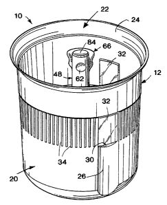
Referring now more specifically to the drawings, the
container 10 includes a receptacle 12, a carrier insert 14 and
a food-handling utensil or implement 16. The carrier and
implement combine to provide means for facilitating the
dispensing of the contents of the container.
The receptacle 12 is cylindrical and includes a slightly
upwardly concave, generally planar bottom 18, a peripheral
wall 20 integral with the periphery of the bottom 18 and
extending vertically upward therefrom, and an open top 22
defined by an outwardly flared upper rim portion 24. The
peripheral wall 20 of the receptacle has the circular cross-
r
~
e.,.: ~
21904 ~
section thereof constant or slightly outwardly tapering
upwardly for the vertical height thereof for vertical sliding
manipulation of the carrier 14 within the interior of the
receptacle as shall be described subsequently.
The peripheral wall 20, at three equally spaced points
thereabout, is provided with inwardly formed portions defining
three vertically extending internal ribs 26 extending from the
bottom 18 to approximately one-half of the height of the
receptacle 12. These vertical ribs 26 have smooth constant
cross-sections throughout the height thereof, preferably
arcuate as illustrated, and terminate at the upper ends
thereof in planar shoulders 30 which extend into the interior
of the receptacle at a slight downward inclination. These
ribs function as guides for the vertical movement of the
internal carrier 14, the shoulders 30 functioning as supports
for the carrier when elevated to approximately mid-height
within the receptacle.
Immediately above each rib 26, and the corresponding
external vertical recess formed thereby, the receptacle wall
20 includes a vertically elongate transparent viewing panel or
window 32 extending for approximately one-half of the
remaining height of the receptacle 12. Noting Figures 1 and 4
in particular, the receptacle wall 20, peripherally thereabout
and at equal height with the panels 32, is provided with a
6
P
~~"~..
219504~~
series of spaced vertical stripes 34 of a differing surface
presentation, transparency or the like, providing a
distinctive presentation. The peripheral wall 20 immediately
above the level of the panels 32 presents a smooth band, the
outer surface of which is slightly outwardly offset, as at 36,
with the band also of a distinctive surface appearance, for
example slightly frosted.
The carrier 14 is cylindrical and configured for close
reception within the receptacle while being freely vertically
slidable relative thereto. The carrier 14 includes a bottom
support tray 38 of a downwardly generally convex configuration
which, noting Figure 2 in particular, seats on the bottom 18
of the receptacle 12 with an annular fluid-accommodating space
40 defined therebetween at the outer peripheries in light of
the greater curvature of the tray 38 relative to the
receptacle bottom 18. The carrier further includes a
substantially cylindrical peripheral wall 42 integral with the
periphery of the tray 38 and extending upwardly therefrom to
define an upwardly opening chamber. The combined height of
the wall 42 and tray 38 is approximately one-half the height
of the receptacle 12.
The peripheral carrier wall 42 includes three equally
spaced vertically elongate, outwardly directly recesses 44
defined therein. The recesses are configured to conform to
7
i
21950~T
and slidably receive the receptacle wall ribs 26 and thus, in
the illustrated embodiment, are arcuate in cross-section.
Each of the recesses 44 extends upwardly through the
peripheral edge portion of the bottom tray 38 for the full
height of the peripheral wall 42 other than for a flat
overlying top panel 46 slightly downward and inwardly inclined
to conform to the top shoulder 30 of a receptacle wall rib 26.
As will be appreciated from the drawings, the recesses 44 in
the peripheral wall 42 form corresponding inwardly directed
arcuate ribs. This is preferred to actually forming the
recesses as depressions within a thicker wall, which would
necessitate the use of additional material beyond what is
necessary to provide the desired food-accommodating stability.
In its innermost or fully received position, the carrier
14, with the carrier recesses 44 aligned with the receptacle
ribs 26, seats on the receptacle bottom 18 with the recess
upper panels 46 seating on the upper shoulders 30 of the
receptacle ribs 26. After the readily accessible goods from
the upper portion of the container are removed, the carrier is
vertically elevated to a dispensing position immediately above
the receptacle ribs 26. In order to retain the carrier at
this height, the carrier is slightly rotated to rotatably move
the recesses 44 out of alignment with the ribs 26 whereby the
peripheral edge portions of the carrier bottom 38,
8
Y
_w
219~04'~
circumferentially away from the recesses 44, will rest on the
upper inclined shoulders of the ribs 26, the slope of the
carrier bottom 38 conforming to the inclination of these rib-
formed shoulders 30.
Vertical movement of the carrier 14, as well as the
rotational manipulation thereof, is achieved using a central
stem-like handle 48. The lower end of the stem 48 includes an
integral dome-like base 50 overlying a substantially equal
size central aperture 52 in the bottom 38 of the carrier 14.
The base 50 is upwardly spaced from the bottom 38 and
integrally formed therewith through radially extending bridge
portions 54. As will be best noted from the bottom view of
Figure 10, the bridge portions, following the dome
configuration of the base 50, extend beyond the circular
opening 52 in the bottom 38 and integrally join the bottom 38
radially outward therefrom. The circular opening 52 is in
turn provided with radial open branches 56, one underlying
each bridge portion 54. So formed, the base 50 can be
considered to be upwardly formed from the central portion of
the carrier bottom 38 and integrally retained thereto by the
outer edges of the bridge portions 54, thus providing drainage
apertures peripherally about the outer edges of the base 50,
including along the opposed side edges of each bridge portion
54. So located, and communicating with an open fluid
9
..'
21950~~
accommodating chamber immediately below the raised base 50,
the fluid within the carrier, upon a raising of the carrier,
will flow freely through the bottom of the carrier and into
the progressively increasing space between the upwardly moving
carrier and the bottom of the receptacle. Similar drainage
openings 58 are provided through the carrier bottom 38 at the
base of each recess 44, or more particularly the vertical,
radially inwardly directed projection or rib formed in
defining the recess. Each opening 58 follows the arc of the
recess and, positioned at the outer periphery of the carrier
bottom 38, also allows for liquid drainage into the annular
space 40 at the periphery of the carrier bottom 38 and the
receptacle bottom 18.
It is significant that the drainage openings are
elongate, relatively narrow, and at the relatively protected
lower end portions of the recess forming projections and the
handle base, thus precluding any possibility of foodstuffs
being caught therein or moving therethrough. Similarly, in
light of the sloping portions immediately adjacent the various
drainage openings, there is no tendency for a clogging of
these recesses as might prevent the desired drainage.
The stem handle 48, integral with the base 50, is hollow
and tapers slightly upwardly from the base 50 to the open
upper end 60 of the handle located at.a height generally
'~~.~ L,
219504
coextensive with the outwardly flaring receptacle rim 24 when
the carrier 14 is fully seated within the receptacle. The
upper section of the handle 48, at diametrically opposed
positions, is provided with a pair of recesses 62 which
receive the fingers of a user for a non-slip manipulation of
the handle, and hence the carrier. It will be appreciated
that the gripping recesses 62 are positioned for easy access
thereto even within a filled receptacle. It will also be
recognized that the use of a single central handle, in the
nature of a vertical stem, allows for free access to the
interior to the container completely thereabout, as compared
to a bail handle which both restricts access from the side of
the container and the top of the container.
The handle 48 is completed by a pair of vertical slots 64
diametrically opposed from each other and 90° removed from the
recesses 62.
Removal of foodstuff, normally relatively small or
awkward individual pieces, from pickle containers and the
like, is usually facilitated by a fork or pick. The container
of the invention includes a dispensing implement 66 which
is removable stored within the hollow handle 48 in a
cooperative manner. The implement 66, which can be considered
a two-prong fork, includes a vertically elongate body 68 semi-
circular cross-section with transversely opposed flat elongate
11
P
....
21904 '~
edges 70 which terminate in a pair of tapered depending prongs
72 having opposed inwardly directed gripping lugs 74. The
vertically elongate body 68 is sharply upwardly beveled, as at
76, from the lower ends of the edges 70 to define an opening
78 between the lower portions of the edges 70 which in turn
forms the prongs 72. It is contemplated that the prongs 72 be
of sufficient rigidity as to appropriately "spear" the
foodstuff for removal. Similarly, the prongs can have a slight
degree of resilient flexibility to provide a gripping action.
The upper portion of the implement 66 includes a top cap
84 and is provided with a pair of laterally projecting
coplanar wings or projections 80 which are generally in the
plane of the forward vertical edges 70 and joined by an
intermediate portion 86 extending diametrically across the cap
84. The projections include outer edges 82 with a wave-like
configuration of alternating depressions and extensions to
facilitate a grasping thereof.
The diameter of the fork implement 66, in the plane of
the longitudinal edges 70 thereof, is such as to allow the
implement to be closely although slidably received within the
handle 48 through the open upper end 60 thereof. The
projections 80, in turn, are received within the opposed
handle slots 64 which are of a depth sufficient to receive the
projections 80 substantially fully therein with the top cap 84
12
219504'
of the implement body 68 aligned with and closing the upper
end 60 of the handle 48. Once fully received within the
opposed slots 64, the implement projections 80 can actually be
used as an assist in rotating the carrier to and from its
dispensing position above the receptacle ribs 26.
As the implement is to be closely received within the
handle 48, the semi~cylindrical wall of the body 68, along the
rear face thereof opposed from the plane of the forward edges
70, is provided with a substantially full height flat portion
88, forming a minor space between the implement and the inner
surface of the handle 48 to avoid any tendency of the
implement 68 jamming within the handle 48.
As will be appreciated from Figures 1 and 2, the nested
implement has the upper end generally aligned with or only
very slightly above the upper edge of the receptacle 12. As
such, there is no interference with the mounting of a
removable lid over the receptacle. While no such lid has been
illustrated, a lid for the container would preferably be
configured in the manner of the lid in the above referred to
patent to DeCoster 5,082,135.
As will be recognized, the range of foodstuffs which can
be accommodated in the container 10 is limited only by size,
and can vary, as an example, from pickles or olives in a
preservative, to cherries or food slices in an appropriate
13
r
'T~, r
2190
syrup. The components of the container, that is the
receptacle, carrier and fork implement, are completely
separable for cleaning purposes, and the receptacle itself is
of an attractive appearance complementing tableware for use as
a serving dish.
The foregoing is considered illustrative of the
principals of the invention. As variations and modifications,
within the parameters of the invention, may occur to those
skilled in the art, it is not desired to limit the invention
to the exact construction and manner of use specifically
described.
14
y