Note: Descriptions are shown in the official language in which they were submitted.
WO 96/02184 2 1 9 5 0 7 5 PCT/US95/08864
,
- 1 -
Descnption
METHOD AND APPARATUS FOR DETECT~G BARRETT'S
METAPLASIA OF THE ESOPHAGUS
Technical Field
This invention relates to medical diagnostic devices, and more
particularly, to~a method and app~lus for observing t_e esophageal wall and
m~cllring the position of colonmPtric changes to diagnose Barrett's
10 metaplasia.
Back round of the Invention
Chronic reflux (he~l}Jul~) damages t_e lining of the esophagus
by repeatedly exposing it to stom~rh acid. This ~m~ge is believed to lead to
15 the repl~cem~nt of the normal stratified squamous esoph~ge~l lining with a
columnar mucosal tissue. The conversion of the normal lining tissue to
columnar tissue is called Barrett's metaplasia.
Barrett's metaplasia is a pl~cul~or and an important risk factor
for cancer of the esoph~lc- About 25 million Americans suffer persistent
20 chronic healLb~, and 10% of those will develop Barrett's m.ot~rl~ci~
Patients with Barrett's metaplasia are from 10 to 125 times more likely to
develop cancer of the esophagus than the general population. Cancer of the
esophagus is fairly common, with about 30,000 cases per year cullelllly
reported in the United States. Cancer of the esophagus is also deadly, with a
25 five-year survival rate of about 7%.
Cullclllly~ Barrett's metaplasia is ~i~gnose~ by endoscopy once
symptoms have become severe enough to ~em~nd endoscopy ex~min~tion
However, at this point, about 5% to 10% of the patients en~lQscopically
e~mined and found to have Barrett's metaplasia already have cancer of the
30 esophagus. Unfortunately, endoscopic e~c~min~tion for Barrett's metaplasia istoo expensive and time-conCllming for routine mass screening of patients
suffering persistent chronic he~ Ll,ulll. If a feasible and cost-effective
technique could be developed for detecting Barrett's metaplasia before it has
progressed to cancer of the esoph~ls, it would be possible to monitor
3j patients with Barrett's metaplasia periodically, such as every six months to
two years, to detect a transition to precancer (dysplasia) or to esophageal
- 21 95075
' ~ . '
canc~ ~ y s~oe. E~r~y de~e~cn of ~sophaoe~l c~nce. would ~nproYe
the rate of sur.~i~al be~se esophaa~o~ c~ce~, when dia~osed at an e~rIy
staae, is mor~o, like}y to be su~cally c~2rable than when dia~osed at an
ad~anced stage.
The linino of a no~mal esophaans is pe~rly white, while the
linina of a noImal stom~ch is salmon pi~k. rne white-to-pi~c junc~on
no~nally occ~rs at a de?th of ;q to 41 cm from the teeth of a patient. In
- - patie~ts with ~aIIe~s me~plasia, the w_ite-to-pin~ junc~on may oc, ur 21 tO
25 cm from the tee~h of the patier.t. At this leYel, the color çh~n-oes from
white to pink a jlmc~don called the ora se~ta The abno~ally hioh loca~ion
of this tr~nCition is noImally used t~ diaanose Bar~etts metapIasia du~ino
endoscopic e~rnin3tions. If the ora se.~ata is located unusually hioh in the
esoph~olls biopsies are ta~e~ of the !inino below the ora se~rata lhese
bioFsies are e~.lmin~Q~ with a mic.oscope to ma~e a diagr~osis of Ba~e~;
15 met~p~s~ rne e~doscopic e~min~ticn mus. be perfo~me~i c~refillly by a
hiohl~ t,~ed and ~e~,e~ced e~doscopi~.. It is not c;~ ly re~lis~c to
~ ~L~ to screQ~ all parie~s wit~ he~lL~ e~doscopically bec use OI
limi~tions in pe~s~el ~me invol~e~ in c'e~ning the e~doscope aIld
e~pense.
One technique for detecting enterogastic reflux based on the
characteristics of electromagnetic radiation is disclosed in
European patent application No. EP 323 816. This application
discloses detecting the absorption by gastric juices of
electromagnetic radiation at two wave lengths to detect high
bile concentration.
A~AENDED S~cET
2a 21 95075
In summa~l, the-e is c~rently no quic~, relatively ine~mensive
scree~iDg tec~nique that could be use~l by rel~tively untraine~ medic~l
practiticne-s to de2e~ Ba.rre~, me.+ pIasia As a result, no feasible and cost-
e~ective meqns c~l~ 'y e.Yist for the mass scre~runa of reflux esophaoitis
pa~e~ts in order to detect Barre~s metaplasia.
Surnmarv of the Inve~on
It is an objeet of the invention to provide a method 2nd
appar~tus for de+ec~o Ba~ett'; me+~p~si~ that is su~ciently quick and
inexpe~siYe that it can be used for mass scree~no of potentiq~ Barr tt's
metaplasia.
It is anothes object of the invenhon to provide a method and
appar~hs for detee~o Ba~ert's me+~plasia that c~n ef,ectively be used bv
relatiYely u ~.~med medic31 prac~itioners.
It is s~ll another obje~t of the inv,enrio~ to pro~ide a method and
apFar~t~ls for de+ee~n~ B~x+.~; me+~plas.a with a o~eat de~1 of ~cc~cy.
21 95075
~0 96/02184 PCTrUS95/08864
- 3 -
These and other objects of the invention are provided by a
system including a probe mounted a~ a distal end of a flexible c~theter. The
probe inclu~es an illllmin~tor and a light receiving device each of which are
directed radially outward toward the esoph~e~l wall. As a result, the
5 illllmin~tor and a light receiving device ill--min~te the esoph~ge~l walL and
receive light from the esoph~e~l wall. A sPncin~ device coupled to the light
receiving device provides an in-lic~tion of the color of the esoph~e~l wall
The light Lo~ l}le illllmin~tor is preferably of a color other than red, such asblue or green, so that the a red or salmon pink esophageal wall will not
10 si~nific~ntly reflect the ill.. ~ or's light, but rather absorb it. As a result,
the int~,ncity of light reflected from a normal white esophageal wall will be
si~ificantly ~lifferent from the int~ncity of light reflected from an abnormal
pink esophageal wall. However, full color spectrum sencin~ or im~ in~ can
also be used.
In use, the probe is inserted into the esophagus and then
withdrawn while noting the position of the probe using a position measunng
device. As a result, the location of a colorimetric change at the ora serrata ofthe esoph~e~l wall can be ~lele~ e~ to detect Barrett's metaplasia.
The ill-....i.~:~t~r preferably includes a first fiber optic waveguide
20 extending through the catheter from a proximal end to a lig}lt opening in thedistal end of the probe. A light source ext~n~l to the c~hPt~r can t_en direct
the illllmin~tin~ light into the fiber optic waveguide. An optical reflector
axially spaced from but facing toward the distal end of the fiber optic
wavegude may be used to redirect and focus t_e illllmin~in~ light in a
25 radially ouLward direction toward the esoph~e~l wall. The light receiving
device preferably inclll~es a second fiber optic waveg~ude çxt~n(lin~ coaxially
through the catheter around the first fiber optic waveguide. The sensing
device is then optically coupled to the proximal end of the second fiber optic
wavegulde.
The probe may be surrounded by a flexible transparent balloon.
The probe may illllmin~te and receive light from a plurality of radial
directions at the sarne tirne. ~;t~rn~nveiy, tne probe may receive light firom alimited range of radial directions but be rotated to cilcu~ferentially scan the
esophageal wall. In the event cilcu-llrerential sc~nning, is used, the catheter
35 may be coupled to a motor and to a rotary encoder or transducer to provide an indication of the angular orientation of the probe.
2 1 q5075 : ~ ;
- 4 - ,,
. .
The position measuring means may compn~e a ma~etic field
gene~ator mounted at a stationa~ position rela~Ye to the esoph~-s, and a
m~anetic field sensor mounted on the catheter. As a result, the relative
position b~ the m~enc field generator and the magnetic field se~sor
5 cullca~onds to the position of the probe along the lenath of the esoph~ c
,~lt~ tively, the position me~suring means may comprise a staionary
reference member attached to a patient about the patient's mouth. The
relative posiio~ between the stationary reference member and the c~thetor can
therl be det~ ed to provide an indication of the position of the probe along
10 the length of the esopha~us. The position measu~ing may also comprise a
wheel fnctionally enC~in~ the c~thcot~r and positioned with the rotational a~cisof the wheel perpendicular to the lon~tl~in~l axis of the c~het~r. As a result,
the wheel rotates responsive to axial movement of the c~theter, and a rotary
encoder coupled to the wheel provides a signal in~iC~nve of the aYial position
15 of the catheter. An optical system can also be used to keep tracl~ of the
inser~on depth of the catheter.
The sensing device may include a device for simply d~t ~ Ill;ll;llg
the color of the esoph~ae~l wall, or it may include a co~uter or other system
coupled to the light recelvillg device and the posiion measuring device to
20 provide an image of the csoph~a~l wa11 and the loc~ion of the ora serrata. Itmay be best to use this catheter with a fle~ible sheath over the portion to be
inserted into the esophagus. The sheath would ha~re a ~ arent tip such that
the light introduced would illnmin~te the esophaaus and the rc(~ ht
would come bac~ through the tip of the sheath to the sensor. Ihis sheath ca~
25 be inc~ by sli htly infl~tin~ the sheath with air pressure as described in
United States Patent No. 4,646,722 PROTECTrVE ENDOSCOPE SHE4.1H
AND ~IETHOD OF INSTALLING SA,M~,~;c~, is i"~orpor~ted hgr~in b~
~f~o. A simil~r infl~ou method can be used to remove the sheath after
use. This she2~it would be disposable, ine~pensive and a ow rapid tLtL,t
30 around of the cat~.teter, avoiding t~te cons~Tning and e:~pensive cle nir.tg and
disinfection.
Bnef Descriotion of the Drawinos
Figure 1 is a flow chart showing the me~tod of detecting
35 Barrett's met~plasia of the esopha~us according to the invention.
A~'AENDED SH~tr
-
21 q5075
WO 96/02184 PCT/US95/08864
- 5 -
Figure 2 is a sçhPm~tic ill~l~ g the basic co~ onents of a
~refelled embodiment of the inventive a~pa,~Lus in use to detect Bar,rett's
metaplasia of the esoph~-c
Figure 3 is an isometric view of a probe used in the embo~lim~nt
5 of Figure 2.
Figure 4 is a schematic of an illnmin~ting and light detecting
module used in the embodiment of Figure 2.
Figure 5 is a sc~em~tic of a position measuring module used in
the embodiment of Figure 2 to measure the position of the probe of Figure 3
10 along the length of an esophagus.
Figure 6 are drawings of two images obtainable using the
embodiment of Figure 2 to diagnose Barrett's met~pl~ of the esorh~-c
Figure 7 is a drawing showing color histograms obtainable using
the embodiment of Figure 2 to diagnose Bar,rett's metaplasia of the esoph~-c
Figure 8 is a sçh~m~ic illustrating the basic components of an
~lt~n~ive embodiment of the inventive a~pal~lus in use to detect Barrett's
metaplasia of the esophagus.
Figure 9 is a sch~m~tic illu~ ~g the manner in which fiber
optic waveguides used in the embodiment of Figure 7 are arranged to deliver
20 and return light from the esoph~g~l wall.
Figure 10 is a schem~t;c view of an ~lt~n~ive embodiment of
the inventive ap~ lus to detect Barrett's metaplasia.
Figure 11 is a srhem~1ic illu~lla~i~g an ~lt~tive technitlue for
measuring the position of the probe of Figure 3 along the length of an
25 esoph~s
Detailed Description of ~e Invention
The m~nner in which the inventive system can be used to
efficiently screen a large populous for Barrett's metaplasia is illustrated in
30 Figure 1. As mentioned above, patients with reflux syrnptoms have the
hi~h~st probability of having Barrett's metaplasia. These patients will present
to general practitioners as well as ga~L,oil.le~ l specialists with reflux
Sylllptollls, as shown at step 10 of Figure 1. As mentioned above, there are
~;ullc~ y about 25 million people in the United States who have persistent
35 chronic he~Lt~ and are thus at risk for Barrett's metaplasia. It is feasible to
screen this large popula~on at step 12 using the inventive system because the
WO 96/02184 2 1 9 5 0 7 5 PCT/US95/08864
system allows screening to be accomplished quickly and inexpensively by
relatively untrained medical practition~rs. The results of the s~;.e~-ng step 12can be quickly reviewed by a physician at 14 to ~et~nnine the location of the
pink-to-white junction along the length of the esophagus. The physician
5 makes this det~ tion at 16 and, if the junction is about 39 11 cm from the
teeth, releases the patient at 18. Otherwise, the patient is selected for a morerigorous endoscopic çx~min~hon at 20. Although endoscopic e~ tion is
fairly expensive, only about 10% to 15% of the p~tientc screened will require
endoscopic e~min~*on
As described in greater detail below, the screening step 12 is
accomplished by introducing a small probe via the nose or the mouth into the
stom~h This probe, which is mounted at the distal end of a catheter, emits
min~*on light about the wall of the esophagus ~djac~nt the probe and then
senses the color of the ~ c~nt esoph~e~l wall. Once the probe is placed in
15 the stom~h about 50 cm from the incisor teeth, the catheter is gradually
withdrawn up the esophagus while the depth of the position of the probe m
the esophagus is measured. The location at which the pink stom~h lining
ch~nges to white esoph~e~l lining provides an in~isation of whether or not
the patient has Barrett's m~t~pl~ci~ The entire sc~nning step 12 will talce very20 little time and can be accomplished by relatively untrained medical personnel.
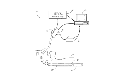
One of the embo~lim~ntc of the inventive system is illustrated in
Figure 2. The system 30 incllldes a probe 32 which is mounted at the distal
end of a long flexible c~theter 34. The c~thet~r 34 is inserted into the nose ormouth of a patient P and e~rtentlc through the esophagus E so that the probe 32
25 is in or near the patient's stom~çtl
With further reference to Figure 3, the probe 32 includes a
lens/prism holder 36 that is optically coupled to a fiber optic waveguide 38.
The fiber optic waveguide 38 is divided into two distinct bundles (not shown
in Figure 3), a first bundle for coupling ill~ ;on light to the lens/prism
30 holder 36 and a second bundle coupling light or an image from the lens/prism
holder 36. The lens/prism holder 36 includes an optical port 40 through
which the esophageal wall E is illllmin~te~ and optically ex~minp~ in a single
direction. A transparent flexible balloon 42 surrounds the lens/prism holder
36 to space the esophageal wall E from the lens port 40 and accurately
35 position the probe 32 in the center of ~e esophagus. The transparent balloon
21 95075 ; '
42 is inflated by couplillg press~m7O~ air into it ~om an ~ source, as
explained in _reater det~il beIow. ~ '
lhe lenslprism holder 36 is mounted within a Te~on sleeve 52,
which is, in tu~, preferably covered with a disposable sheath 54 of a suitable
5 m~t~ri~l such as latex. A cylin~riç~l drive cable 56 is positioned wit~in the
Te~on sleeve 52 surrounding the fiber optic wavegLude 38. The fiber optic
waveguide 38, drive cable 56, Teflon sleeve 52 and sheath 54 togethes form
the carhetPr 34~that ~trn~1c from the probe 32 to a location outside of the
body of the p~ti~nt As e~l~ine~ below, the drive cable is rotated by a
10 suitable device to rotate the lens/prism holder 36 and cause it to
~ ;u~Le~Lially scan the esoph~oe~l wall E. lhere is suf~cient space
between the drive cable 56 and the Te~on sleeve 52 to provide for the passage
of air into the balloon 42 to selectively inflate the balloon 4'~.
As best shown in Figure 2, the c~th~ter 34 e~ n~l~ outside of the
15 body of the patient and t~in~tes in a li ht-sc~nning and position-sensing
module 60 on w_ich is mounted an inflation syrin_e 62. The in~ation s~ringe
62 is pneumatic311y c~upled to the inside of the Teflon sle~ve 52 to pnmp air
the.~u~ and illflate the balloon 42. As explained below, the module 60
also incl~ties a motor for rotahn_ the drive shaft 56, an encoder for s~n~ing
20 the rotational position of the drive shaft 56, and a three~im~n~ional position
sensor which detects the position of the module 60 by se~sing magnetic fields
generated by a conventional magnetic field generator 64. By knowing the
three--iim~ncional posi~on of the module 60, the movement of the module 60
along the axis of the catheter 34 can be det~.",;"ed in order to provide an
25 indication of the movement of the probe 32 through the esophagus.
The light-sc~nnino and position-sensino module 60 is
electrically and opacally coupled to a light source and detector module 68
which is, in tu~, connected to a conventional COLUPU~eS 70. The li_ht source
and detector module 68 includes a light source for supplying light to the fiber
30 optic waveguide 38 (Figure 3), and optical s~stem for receiving light throuahthe fiber optic waveguude 38 reflected from the esophageal wall. The module
68 also couples position info~mation indicative of the axial and rota~ional
posi~on of the probe 32 to the co.~l,uter 70. lhe co~pllter 70 then provides
information to the medical practitioner in a varietv of formats to allow the
35 position of the pink-to-white transition on the esophage~l wall to be
dete~mined.
D~;~
WO 96/02184 2 1 ~ 5 0 7 5 PCT/US95/08864
- 8 -
The light source and detector module 68 is shown in greater
detail in Figure 4. As mentioned above, the fiber optic waveguide 38 is
divided into two discrete bundles 38A, 38B, one of which 38A couples
min~tion light to the probe 32 and the other of which 38B couples light
5 reflected from the esoph~ge~l wall. The illllmin~tion bundle 38A receives
light through a conventional coupling device 80 from a quar~ tungsten
halogen lamp light source 82 which is driven by a conventional power supply
84. Tlll~min~tiTr~ devices to apply illllmin~tin~ light to a fiber optic waveguide
are in common use and are thus conventional.
The light reflected from the esophageal wall is processed to
provide si~nals indicative of the int~ncity of each of several colors. ~eflectedlight from the fiber optic bundle 38B is applied throug~ a conventional
coupling me~h~nicm 90 to a 45 degree dichroic blue reflector 92 which
reflects the blue portion of the incoming light through a blue corrector filter
15 94 onto a photodiode 96. The photodiode 96 generates a signal in~ic~tive of
the amplitude of the incident light in a conventional manner. This signal,
which is indicative of the intenCit~v of blue light coupled through the fiber
optic bundle 38B, is boosted by an amplifier 98 and sampled by conventional
sample and hold circuit 100. Similarly, the rem~ining light passing through
20 the blue dichroic reflector 92 is incil1~nt on a 45 degree dichroic red reflector
104 which re~ects the red portion of the light through a red corrector filter
106 and onto a photodiode 108. The signal from the photodiode 108
indicative of the in~ncity of red light is boosted by an amplifier 110 and
applied to a second sample and hold circuit 112. The rem~inin~ light p~scing
25 through the red dichroic reflector 104 passes through a green corrector filter
116 to a third photodiode 118. The signal from the photodiode 118, which is
indicative of the int~nci1y of green light, is boosted by a third ~mplifier 120
and sampled by a sample and hold circuit 122. A multiplexer 124
seq~len~i~lly selects a sample of one of the colors from the sample and hold
30 circuits 110, 112, 122 and applies the sample to an analog-to-digital converter
126 which outputs a digital value indicative of the color and int~ncity to the
coll,yulel 70 (Figure 2). As explained below, the computer 70 processes this
color information in a variety of m~nnerS to provide information from which a
practitioner determine the location of ~e pink-to-white transition on the
35 esoph~gç~l wall.
WO 96/02184 2 1 9 5 0 7 5 PCT/US9_/08~
_ 9 _
Although a white light source and a multiple color (blue, red,
green) light source and detector are shown in Figure 4, it will be understood
that a fewer number of colors, inclllding a single color, may be used. The
advantage of the multiple color system shown in Figure 4 is that it can be used
S to provide full color images of the esophageal wall. However, the pink-to-
white transition of the esophageal wall can be detected by only a single color
of light, particularly of a color other than red. For example, there will be very
little green ligh-t reflected from the pink stomach and lower eso~h~ge~l lining,but green light will be reflected to a subst~nti~lly greater extent by the white10 lining of the upper esoph~s. Thus, by e~ ;ni~lg the intf nci1y of reflected
green light, the pink-to-white transition of the esoph~,oe~l lining will be
readily apparent by the large increase in inten~ity of the reflected signal as the
probe 32 passes from the pink esophageal lining to the esoph~ge~l white
lining. In this case a green helium-neon laser could be used as the
15 ill~ ;on source.
The light-sc~nning and position-sf~sing module 60 (Figure 2) is
shown in ~eater detail in Figure 5. The disposable sheath 54 ~ s at
the entrance to the module 60 while the Teflon sleeve 52 If ~ les at an
inflation collar 130 to which the inflation synnge 62 (Figure 2) is coupled
20 t_rough inflation tube 132. As mentionf d above, co~ ,cssed air applied to
the inflation tube 132 is coupled in the space ~eLw~ell the drive cable 56 and
the Teflon sleeve 52 to inflate the trans~aLe~l balloon 42 (Figure 3). The
sleeve 52 extends into the module 60, and the dnve cable 56 projects beyond
the inside end of the sleeve 52 and tçnT in~tes in a pinion gear 136. The
25 pinion gear 136 meshes with a second pinion gear 138 that is coupled to an
electric motor 140 and an ~n~ r position sensor 142 of conventional design.
In operation, the motor 140 rotates the probe 32 through the drive cable 56,
and the rota~onal position of the probe 32 is indicated by the output of ~he
~n~ r position sensor 142. A conventional magnetic field detector 144
30 provides an indication of the position of the module 60 in three dimensions
relative to the magnetic field generator 64 (Figure 2).
The fiber optic waveguide 38 projects beyond the gear 136 and
tennin~tes at a spherical lens 150 which couples li~ht from the rotating fiber
optic waveguide 38 to a stationary fiber optic waveguide 152. The stationary
35 fiber optic waveguide 152 is coupled to the fiber optic waveguide 78 of the
light source and detector module 68 shown in Figure 4.
WO 96/02184 2 1 9 5 0 7 5 PCT/US95/08864
- 10-
As mentioned above, the co~ uLcr 70 (Figure 2) can display the
light and posihonal information from the module 68 in a varietv of formats to
allow a medical practitioner to dc(et~ e the location of the pink-to-white
transition of the esoph~e~l wall. One format for supplying t_e light and
5 positional information is a full color image as shown in Figures 6A and 6B.
In both of these figures, the rotational position of the probe 32 is shown on the
Y axis and the position of the probe 32 along the length of the esophagus is
shown in the ~ axis. The color of each pixel corresponds to the color and
int~ncity of light received by the probe 32 at the corresponding rotational and
10 axial position. The image shown in Figures 6A and 6B can be obtained by
simply lecordillg in suitable memory sets of data for each incrPnlent~l axial
position of the probe 32. Each set of data incll~es for each ~n~ r position
of the probe 32 the int~n~ity of the blue, red and green samples output by the
analog-to-digital converter 126. The m~nne~ in which a co~u~u~er can
15 perform this function is convention~l and thus, in the interest of brevity, not
explained herein. The pink-to-white tr~n~ition of the esoph~g~l wall is
shown in Figare 6A as occurring at about 40 cm, thus in(lis~tin~ that the
patient does not have Barrett's m.et~pl~ci~ Figure 6B shows the pink-to-white
transition of the esoph~e~l lining occllrrin~ at about 28 cm from the teeth of
20 the patient, thus inAicting that the patient may have Barrett's metaplasia and
should be screened further by endoscopic e~min~tion and biopsy as
illustrated at 20 in Figure 1.
The information stored in the co~ uler 70 to provide the images
shown in Figures 6A and 6B can also be used to calculate and display
25 histograms as shown in Figure 7. Each of the histograms shows the intPnsity
of a specific color of light (Y axis) as a function of the axial position of theprobe 32 (X axis). The histograms shown in Figure 7 do not provide any
inf~rm~sion about color as a function of the rot~tion~l position of the probe
32. Tn~te~, the histogram inform~tion at each axial position (shown on the X
30 axis) is an average of the inten~ities at all sampled radial positions. The
histograms of Figure 7 compare the blue, green and red reflected light a~ove
(upper set) and below (lower set) the ora serrata. In Figure 7, the red light
characteristics remain the same (since red is reflected equally from white and
pink tissues) but the green and blue content of the reflected light is different35 above and below the ora serrata. This difference makes detection of the ora
serrata easier with blue or green light compared to red or white light.
~VO96/02184 2 1 9 5 0 7 5 PCT~S95/08864
An ~ltern~tive embodiment of a system for ~etectin~ Barrett's
metaplasia is shown in Figures 8 and 9. The embodiment of Figures 8 and 9
differs from the embodiment of Figures 2-5 in that it utilizes a probe 160 that
simnlt~neously scans in 360~ and thus need not be me~nically rotated to
5 image entirely around the probe 160. The embodiment of Figures 8 and 9
uses an im~ging and i1lnmin~tion bundle 162 which, as illustrated in Figures
9A and 9B, consists of an inner fiber optic bundle 166 ~ ou~lded by a
concentric spacer 168 which is, in tum, ~ ou~ded by a plurality of optical
fibers a~anged in a cylinder 170. The inner light bundle 166 iS used to
10 conduct illllmin~tin~ light to the probe 160, while each of the optical fibers
170 conducts reflected light from a discrete radial direction from the probe
160.
As best illustrated in Figure 8, the im~ng bundle 162
~nnin~tt~S behind a generally conical mirror 164 which directs and focuses
15 light from the illnmin~tin~ bundle 166 in a 360~ ch~ rclltial arc around
the c~ ç.. Light reflected from the esoph~e~l wall is then reflected by the
conical mirror 164 to the optical fibers 170. Since the optical fibers 170
extend around the ci~ ferel.ce of the bundle 162, they each receive
reflected light from a discrete ~n~ r position about the probe 160.
The ~l~,~al end of the im~ging and ilhlmin~tion bundle 162
fits into a coupling member 170 so that the fiber optic bundle 162 and probe
160 can be easily replaced. The coupling member 170 includes a cylin~lric~l
recess 172 that receives a collar 174 secured about the ~ro~al end of the
im~in~ and illnmin~tion bundle 162. An ~nmll~r groove 176 formed in the
collar 174 receives a resilient ring 178 lining the inside of the cylintlric~l
cavity 172 to lock the collar 174 in position within the cavity 172. When the
collar 172 iS in position in the cavity 172, the distal end of the im~ing and
illnmin~1ion bundle 162 abuts an im~gin~, and illnmin~tion fiber optic bundle
180 positioned in the coupling member 170 through an index m~tching gel
182. The fiber optic bundle 180 ext~n(ls to a transition member 184 in which
the optical fibers 170 are separated from the illl-min~tin~ light bundle 166.
The illllmin~ting light bundle 166 is coupled to a conventional light source
190, while the optical fibers 170 are arranged in a flat configuration and
coupled to a photodiode array 192, which is best illustrated in Figure 9C. The
35 photodiode array 192 preferably includes a sensing cell for each optical fiber
170, with each cell co~ three light sensors receiving light through
WO96/02184 21 95075 PCT/USgS!C-~ ~
- 12-
respective red, green and blue filters. As mentioned above, multiple light
sensors allow for full color im~inp of the esophageal wall. However, as with
the embodiment of Figures 2-5, single color im~in~ may be used. Also,
although 360~ sc~nning of the esophageal wall is preferred, it will be
5 understood that multiple direction (e.g., 0~, 90~, 180~ and 270~) or single
direction sc~nning may also be used.
It should be understood that a technique that does not rely on
c.r~ liar sc~nnin~ may be used. In this technique a segmçnt of the
esophageal wall is illnmin~te~ over the full 360~ as illust~ated in Figure 8. All
10 of the detecte~ light is then passed through a single color separation device as
illustrated in Figure 4. The resnlt~nt out.puts will be the average of red, green
and/or blue values around the cir~u~e~ ce of the illllmin~ted se~nent of the
esoph~ge~l wall.
A ~implifie~ embo-liment of that shown in Figures 8 and 9 that
15 is suitable for this non-scan technique is shown in Figure 10. The
fim~mtont~ elence between this system and the other described systems
is that only a single optic fiber 230 is used in the probe. The illllmin~tion
light exiting the fiber 230 is focused and directed radially from the axis of the
fiber by an essP-nti~lly conical reflector 232 similar to the reflector 164 of
20 Figure 8. Light reflected from the esoph~e~l wall is directed baclc into the
single optical fiber 230 by the reflector 232. The proximal end of the optical
fiber 230 is t~ P~ in a conn~ctor 236 that, with the exception that it
contains only a single optical fiber, is identical to the coupling device 170-182
described in Figure 8. Both the ~ lmin~*on light and the light reflected from
25 the esoph~gç~l wall pass through a single optical fiber 238 extPn~lin~ from the
conn~ctnr 236. The reflected light exiting the optical fiber 238 is directed
onto a reflective beam splitter 240. Fifty percent or more of the light is
deflected away from the axis of the optical fiber 238 and through a lens 244
where it is input to a color sep~tor 246 identical to that described in Figure
30 4. The i1lllmin~hon light is focused on the input face of the optical fiber 238
in the common m~nnçr, but the reflective beam splitter 240 is in the optical
path. The light reflected off of the beam splitter 240 will be lost for
illnmin~tion purposes.
The single optical fiber device shown in Figure 10 has the
35 disadvantage that only fifty percent of the illnmin~tion source light and fifty
percent of the reflected return light is usable, the other fifty percent being
WO96/02184 2 i 9 5 0 7 5 PCT~S9S/08864
-13-
directed away from a useful path by the beam splitter 240. There are,
however, several adv~nt~es The primary and fim~ment~lly most important
is that the optical system is a confocal system. The focus for illl-min~tion hasto be the focus for ~letection Additional advantages are the ease of
5 fabrication, less strin~nt ~lignmlont re4uir~cnl~ than multiple optical fibers,
and the total area of a single fiber is optically usable while a bundle of
equivalent ~ mPt~r has dead areas between the individual fibers.
With the probe embodiment shown in Figure 11, as with others,
only a single color such as green may be used. In that case, the light source
10 may have a green filter on it or only a green light filter would be used with a
single photodiode or other photo sensor. Furthermore, incte~d of a co.,l~uler
being used as a display device, other means of sen~ing color or displaying an
image may be used. For example, a display light may turn on when the
adequate green light has been received intlic~tin~ the probe has crossed the
15 ora serrata during a linear scan of the esoph~ge~l wall. A further simplified system would have distance m~rkingc on the probe somewhat similar to a
ruler. In this case the user would just visibly monitor the m~rkingc as the
probe is withdrawn. When the display indicates the ora serrata has been
reached, the user would just record the distance from the teeth that the sensor
20 is located. A complete simplified system could use the single fiber system
described above, a single color, length m~rkingc on the probe, and a simple
indicator that tllrns on when the ora seIrata has been crossed.
A variety of techniques may be used to provide an indication of
the axial position of the probe 32 (Figure 2) along the length of the esoph~ls
25 As illustrated in Figure 11, the c~9th~tPr34 iS colupressed between a pair of friction wheels 200, 201 so that the wheels 200, 201 rotate with axial
movement of the catheter 34. One of the friction wheels 200iS mechanically
coupled to a conventional angle sensor 204 which provides an electrical signal
indicative of the rotation of the wheel 200 in a conventional m~nner. The
30 angle sensor 204 thus provides an indication of the axial position of the
catheter 34. Other position sensing techniques may also be used as desired.
For example, a device could be placed in the teeth of a patient which would
interact with a mechanical or electrical member e~ten~lin~ along the probe
catheter to provide an indication of the axial position of the probe tip.
35 Although an electrical sensor could be used, it will be also understood that
optical position sensing using m~rlcingc on ~e outer surface of the catheter
21 95075
WO 96/02184 PCT/US95/08864
- 14-
may also be used. Other posi~on m~Cllrin~ techniques, as well as other
fomLc of processing i~ol~dlioll indicative of the color of the esophageal wall,
may a~so be used.