Note: Descriptions are shown in the official language in which they were submitted.
X195258
COAXIAL CABLE FOR PLENUM APPLICATIONS
FIELD OF THE INVENTION
This invention relates to cables for plenum applications. More
particularly, the invention relates to a coaxial cable used for plenum
applications which exhibits flame spread and smoke generation properties
which comply with industry standards.
BACKGROUND OF THE INVENTION
Buildings are often times designed with a space between a drop ceiling
and a structural floor from which the ceiling is suspended to serve as a
return
io air plenum for elements of heating and cooling systems as well as serving
as a
convenient location for the installation of communications cables and other
equipment, such as power cables. Alternatively, the building can employ
raised floors used for cable routing and plenum space. Communications cables
generally include voice communications, data and other types of signals for
use
in telephone, computer, control, alarm, and related systems, and it is not
uncommon for these plenums and the cables therein to be continuous
throughout the length and width of each floor, which can introduce safety
hazards, both to the cables and the buildings.
When a fire occurs in an area between a floor and a dmp ceiling, it may
2o be contained by walls and other building elements which enclose that area.
However, if and when the fire reaches the plenum space, and especially if
flammable material occupies the plenum, the fire can spread quickly
throughout the entire floor of the building. The fire could travel along the
length of cables which are installed in the plenum if the cables are not rated
for
plenum use, i.e., do not possess the requisite flame and smoke retardation
characteristics. Also, smoke can be conveyed through the plenum to adjacent
areas and to other floors with the possibility of smoke permeation throughout
the entire building.
X195258
2
As the temperature in a non-plenum rated jacketed cable rises, charring
of the jacket material begins. Afterwards, conductor insulation inside the
j acket begins to decompose and char. If the charred j acket retains its
integrity,
it still functions to insulate the core; if not, however, it ruptures due
either to
expanding insulation char or to pressure of gases generated from the
insulation, and as a consequence, exposes the virgin interior of the jacket
and
insulation to the flame and/or the elevated temperatures. The jacket and the
insulation begin to pyrolize and emit more flammable gases. These gases
ignite and, because of air drafts in the plenum, burn beyond the area of flame
1 o impingement, thereby propagating flame and generating smoke and toxic and
corrosive gases.
Because of the possibility of flame spread and smoke evolution, as a
general rule, the National Electrical Code (NEC) requires that power-limited
cables in plenums be enclosed in metal conduits. However, the NEC permits
certain exceptions to this requirement. For example, cables without metal
conduits are permitted, provided that such cables are tested and approved by
an independent testing agent, such as Underwriters Laboratories (UL), as
having suitably low flame spread and smoke generating or producing
characteristics. The flame spread and smoke production of cables are
2o measured using the UL 910 standard test method for fire and smoke
retardation characteristics of electrical and optical fiber cables used in air
handling spaces, i.e., plenums.
Communication systems in the present day environment are of vital
importance, and, as technology continues to become more sophisticated, such
systems are required to transmit signals substantially ermr free at higher and
higher bit rates. More particularly, it has become necessary to transmit data
signals over considerable distances at high bit rates, such as megabits or
gigabits per second, and to have substantially error free transmission. Thus,
21 ~~~~~
3
desirably, the medium over which these signals are transmitted must be
capable of handling not only low frequency and voice signals, for example, but
higher frequency data and video signals. In addition, one aspect of the
transmission that must be overcome is crosstalk between pairs of commercially
available cables. One of the most efficient and widely used signal
transmission
means which has both broadband capability and immunity from crosstalk .
interference is the well known coaxial cable.
The coaxial cable comprises a center, conductor surrounded by an outer
conductor spaced therefrom, with the space between the two conductors
1o comprising a dielectric, which may be air but is, most often, a dielectric
material such as foamed polyethylene. The coaxial cable transmits energy in
the transverse electromagnetic (TEM) mode, and has a cut-off frequency of
zero. In addition, it comprises a two-conductor transmission line having a
wave
impedance and propagation constant of an unbounded dielectric, and the phase
t 5 velocity of the energy is equal to the velocity of light in an unbounded
dielectric.
The coaxial line has other advantages that make it particularly suited for
efficient operation in the hf and vhf regions. It is a perfectly shielded line
and
has a minimum of radiation loss. It may be made with a braided outer
conductor for increased flexibility and it is generally impervious to weather
2o effects. Inasmuch as the line has little radiation loss, nearby metallic
objects
and electromagnetic energy sources have minimum effect on the line as the
outer conductor serves as a shield for the inner conductor. As in the case of
a
two-wire line, power loss in a properly terminated coaxial line is the sum of
the
effective resistance loss along the length of the cable and the dielectric
loss
25 between the two conductors. Of the two losses, the resistance loss is the
greater
since it is largely due to skin effect and the loss will increase directly as
the
square root of the frequency.
X195258
4
The most commonly used coaxial cable is a flexible type having an outer
conductor consisting of copper or aluminum wire braid, with the copper or
aluminum inner conductor supported within the outer by means of the
dielectric, such as foamed, or expanded, polyethylene (XPE), which has
excellent low-loss characteristics. The outer conductor is protected by a
jacket
of a material suitable for the application, such as, for example, for non-
plenum
use, polyvinyl chloride) (PVC) or polyethylene (PE).
The coaxial cable most preferred for its performance characteristics for
non-plenum uses has an XPE dielectric and PVC jacket. However, the use of
1 o XPE dielectric material and a PVC j acket generally does not result in a
cable
that satisfies UL 910. The use of foamed perfluorinated ethylene polymers,
such as polytetrafluoroethylene (PTFE) and perfluorinated ethylene-propylene
polymer (FEP), both sold under the trademark TEFLON~, has been suggested
for the dielectric material due to its low flame spread and low smoke emission
characteristics. However, foamed polyethylene is preferable because it is
cheaper and requires simpler processing techniques. When accompanied with
a plenum grade jacket, a cable having an XPE dielectric material will usually
satisfy ITL 910. TEFLON~ is also useful as a plenum grade cable jacket
material. However, TEFLON~ is quite expensive and is currently in extremely
2o short supply, hence is unsatisfactory from an economic standpoint, although
outstanding for its flame and smoke retardation characteristics.
In general, highly flame retardant cable jackets have been made in two
ways. An inert flame retardant additive such as antimony or molybdenum can
be added to an appropriate polymer, such as PVC. Alternatively, or perhaps in
combination, a halogenated polymer that is inherently flame retardant (such as
TEFLON~) can be used alone or as a copolymer.
X195258
It is apparent from the foregoing discussion that what is still sought is an
inexpensive, flame retardant, and low-smoke generating coaxial cable with
excellent
electrical transmission capabilities. The sought after cable desirably is easy
to
manufacture and does not sacrifice transmission properties for fire and smoke
resistance.
5 SUMMARY OF THE INVENTION
In accordance with one aspect of the present invention there is provided a
shielded
coaxial cable which complies with the flame spread and smoke optical density
requirements of UL 910 for a Plenum Cable, said coaxial cable consisting
essentially of:
a core member including a central conductor and a solid dielectric material,
said solid
dielectric material surrounding the length of said central conductor; an outer
conductor
shield surrounding said dielectric material; and a jacket comprising a
halogenated
polymer having a heat of combustion between approximately 2300 and 7000 BTU
per
pound and including a free radical scavenger for flame retardance.
In accordance with another aspect of the present invention there is provided a
shielded coaxial cable which complies with the flame spread and smoke optical
density
requirements of UL 910 for a Plenum Cable, said coaxial cable consisting
essentially of-.
a core member including a central conductor and a dielectric material; said
dielectric
material comprising foamed polyethylene encapsulating the length of said
central
conductor; an outer conductor shield surrounding said dielectric material; and
a jacket
surrounding said outer conductor comprising a halogenated polymer having a
heat of
combustion between approximately 2300 and 7000 BTU per pound and including a
free
radical scavenger for flame resistance, said jacket having a thickness from
between about
0.017 to 0.025 inches.
X195258
Sa
In accordance with yet another aspect of the present invention there is
provided a
shielded coaxial cable which complies with the flame spread and smoke optical
density
requirements of UL 910 for a Plenum Cable, said coaxial cable consists
essentially of
a core member including a central conductor and a dielectric material
comprised of
foamed polyethylene encapsulating the length of said central conductor; an
outer
conductor shield of braided copper surrounding said dielectric material; and a
jacket
surrounding said outer conductor comprising a halogenated polymer, said
halogenated
polymer comprising a copolymer of vinylidene fluoride and 20%
chlorotrifluoroethylene
and a smoke suppressant, said halogenated polymer having a heat of combustion
between
approximately 2300 and 7000 BTU per pound and including a free radical
scavenger for
flame retardance, said jacket having a thickness from between about 0.017 to
0.025
inches.
The foregoing needs have been met by the cable according to an exemplary
embodiment of this invention which includes a core of a central conductor,
generally
copper, surrounded by a dielectric material which is preferably foamed
polyethylene.
An outer conductor surrounds the dielectric material and the so-formed coaxial
arrangement is encapsulated within a sheath system including a jacket made of
a flame
resistant, low smoke producing material which is a halogenated polymer having
a heat
of combustion less than 7000 BTU per pound and including a free radical
scavenger.
The free radical scavenger may be either added to the polymer and/or may be
intrinsic
to the polymer. Examples of suitable polymers are vinylidene fluoride
copolymers
(PVDF-CP), ethylene chlorotrifluoroethylene polymers (ECTFE), and low smoke
PVCs.
The jacket has a thickness of preferably about 17-25 mils. A jacket made in
accordance
with the invention satisfies UL 910 standards for plenum cables.
~; _
X195258
Sb
Other features of the present invention will be more readily understood from
the
following description of specific embodiments thereof when reviewed in
conjunction
with the drawings.
X195258
6
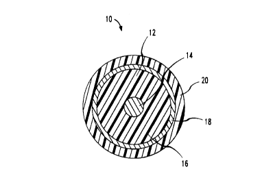
BRIEF DESCRIPTION OF THE DRAWINGS
Figure 1 is an end cross-sectional view of a cable of the present
invention.
DETAILED DESCRIPTION
Referring now to Figure 1, there is shown a communications cable,
which is designated generally by the numeral 10 and is flame retardant and
smoke suppressive. Cable 10 includes core member 12 which comprises an
inner or central metallic conductor member 14 surrounded by dielectric
member 16. The inner or central conductor member 14 is preferably copper or
to aluminum such as is typical for coaxial cables. Dielectric member 16 made
be
any suitable insulating material having adequate dielectric properties and is
most preferably foamed, or expanded, polyethylene. Dielectric member 16 is
surrounded by an outer metallic conductor member 18 which is preferably
copper or aluminum and consists, preferably, of an aluminum tape surrounded
by a copper braid. The coaxial structure formed by the core member and the
outer conductor is in turn encased in a jacket 20 manufactured according to
the
present invention which renders the cable flame retardant and smoke
suppressive.
A foamed polyethylene dielectric member has poor flame spread
resistance and smoke generating properties. However, the excellent dielectric
properties of foamed polyethylene make it desirable as dielectric material for
coaxial cables. The jacket material of the present invention overcomes the
poor
flame spread and smoke properties of the dielectric and enables the cable
manufactured according to the present invention to be used as a plenum cable.
Jacket 20 is made of a halogenated polymer having a heat of combustion
less than 7000 BTU per pound and including a free radical scavenger. The
X995258
inventors have discovered that polymers with a heat of combustion lower than
7000 BTU per pound are suitable for the jacket of the invention as long as
they
either include intrinsically a free radical scavenger or have a free radical
scavenger added thereto. A free radical scavenger acts as a quenching agent
for free radicals, thus removing free radicals, such as ~OH and ~0~, that are
essential for flame propagation. The quenching of free radicals slows the rate
of energy production and results in extinction of the flame. Halogenated
compounds have been shown to act as free radical scavengers by the following
reactions: HBr + ~OH ~ H20 + Br and HBr + ~0~ ~ ~OH + Br~. Inorganic
l0 compounds act to reduce flame propagation in at least two ways, by lowering
the fuel content of the polymer and by acting, in combination with halogen
acids, to promote char formation and to provide an inert blanket over the
j acket, thus excluding oxygen and preventing flame spread. An example of a
commonly used compound is antimony oxide which is converted to a volatile
species by a halogen acid released by a halogenated organic. The resulting
antimony trihalide or antimony halide oxide is the flame suppressant.
Smoke suppression is a function of the fire retarding and smoke
suppressing ability of the jacket polymer material itself as well as the
ability of
the j acket to keep flame away from the smoke-providing dielectric, by being
of
2o adequate thickness and/or by forming a char. In other words, smoke
suppressing ability of a cable jacket is determined by the jacket chemical and
physical properties. Many inorganics also function as smoke suppressants, for
example, antimony, molybdenum, tungsten, zinc, and aluminum, and are
commonly added to polymers to increase the smoke suppression of the polymer.
Preferably, the heat of combustion of the material ranges from
approximately 2300 BTU per pound to approximately 7000 BTU per pound.
Examples of appropriate halogenated polymers include copolymers of
vinylidene fluoride (VFz), ethylene chlorotrifluoroethylene polymers, and PVC
X195258
g
formulated for low smoke emission. Optionally, the polymer may have a smoke
suppressant added thereto. Examples of appropriate polymers are HALAR 379
- a trade name for a plasticized ECTFE; SOLEF 11008/0003 - a trade name for
a VF2/hexafluoropropylene copolymer with a smoke suppressant; SOLEF
32008/0003 - a trade name for a VF~/20% ECTFE copolymer with a smoke
suppressant; SOLEF 32008/0009 - a trade name for a VF~20% ECTFE
copolymer with additional smoke suppressant; and Alpha Gary 6920F1 - a low
smoke formulated PVC. The preferred polymer is SOLEF 32008/0009, sold by
Solway Polymers, Houston, Texas. This polymer has an oxygen index according
to ASTM D2863 of 95% and a UL 94 classification of V-0.
The jacket preferably has a thickness between about 17 and 25 mils
(0.017 to 0.025 inches). A cable prepared with the jacket of the invention
passes UL 910 test for flame propagation and peak optical density and average
optical density, which are measurements of smoke emission.
is TEST RESULTS
Coaxial cables were constructed in accordance with typical coaxial
manufacturing techniques with expanded high density polyethylene (X13DPE)
dielectric material and a jacket of SOLEF 32008/0009 polymer. The cables
included a 26 gauge (0.0157 inch diameter) copper central conductor and
2o XHDPE dielectric with a diameter of about 0.077 inches and about 45-50
degree of expansion. The outer conductor included a first wrapping of an
aluminum and polyester laminant tape covered with a metallic braid of 38
gauge tinned copper wire with a minimum of 90% coverage. One cable had a
jacket thickness of 14 mils and a second was constructed having a jacket
25 thickness of 20 mils. The cables were subjected to the flame test described
in
UL 910 and maximum flame propagation of the cables was measured. Smoke
development was measured with a photometer system and the optical smoke
X195258
9
density was calculated from the light attenuation values. UL 910 test results
are shown in Table 1.
Table 1
735 Type CoaaLal Flame Peak Average
Cable Construction Spread Optical Optical
Density Density
UL 910 Requirement 5 Feet 0.5 0.15
XHDPE Dielectric 7.0 0.66 0.07
with Solef 32008/0009
0.014 Inch Nominal
Jacket Thickness
XHDPE Dielectric 2.5 0.34 0.05
with Solef 32008/0009
3.5 0.42 0.05
0.020 Inch Nominal
Jacket Thickness
The cable constructed with the jacket having a thickness of 0.020 inches
passed the requirements of UL 910 for a plenum cable. The cable having a
jacket thickness of 0.014 inches failed UL 910. A further test indicated that
a
cable with a j acket of 0.016 inch thickness gave marginal results in the UL
910.
From these results, the conclusion is that the jacket should have a thickness
1o above 0.016 inches. The preferred thickness of the cable is thus between
about
0.017 and 0.025 inches. A jacket much thicker than 0.025 would be di~cult to
handle and a thinner jacket fails the UL 910 requirement. However, it is
c~185258
io
possible that a cable having a jacket thinner than 0.017 inch could be within
the scope of the invention if the cable is manufactured with a jacket of
appropriate materials as disclosed in this specification. For example, another
particular combination of a polymer with a heat of combustion between about
2300-7000 BTU per pound and a free radical scavenger could provide adequate
protection from flame spread and smoke generation at a thickness less than
0.017 inches.
Another observation from the UL 910 test was that a char was formed
that isolated the outer conductor and the insulation on the inner conductor.
1o Thus, the insulation and the conductors were protected from flames. Since
the
dielective was protected, it did not produce smoke.
It is to be understood that the above described arrangements are simply
illustrative of the invention. Other arrangements may be devised by those
skilled in the art which will embody the principles of the invention and fall
within the spirit and scope thereof.