Note: Descriptions are shown in the official language in which they were submitted.
ROUNDSLING CONSTRUCTION 2 1 9 5 3 9 3
BACKGROUND OF THE INVENTION
HISTORY OF THE TECHNOLOGY
Industrial slings have been improved in flexibility and
strength during the past two decades. Stiff metal wire rope
slings which were secured by large metal sleeves have been
replaced by smaller termination and closure means. The metal
strands of wire rope have recently been replaced by synthetic
fibers of very high load lifting performance strength which
provide lighter, more flexible and even stronger slings than
the heavier, inflexible and stiff metal wire rope. Even with
such advances in the art of sling making, the riggers who use
these improved slings still suffer and endure some of the age
old problems of sudden failure and loss of a load caused by
a sling breaking suddenly because it was fatigued from being
continually subjected to overload conditions.
There are standard break tests for determining how great
a load a sling can endure before it is unable to withstand
the stress of the test load being applied to it and it
breaks. Such break tests have enabled manufacturers of
industrial slings to rate the load-bearing capacity of the
sling. Most sling manufacturers will affix some type of tag
notice on the sling which states the load capacity (rated
capacity) of the particular sling. This rated capacity gives
the maximum amount of load to which the sling may be
subjected and still be considered a safe use of the sling.
Unfortunately, even conscientious riggers who do not
take unsafe shortcuts and who operate in a safe responsible
manner sometimes are surprised by a sling breaking in use
even when they believed it was being used within the load
limits of its rated capacity. For example, when industrial
slings are in continuous heavy use over three shifts around
the clock, the workers on a later shift may not be aware that
someone on an earlier shift had subjected the sling to a
substantial overload which may have caused serious damage to
the lifting core yarn material of the sling. When a
1
CA 02195393 2000-04-13
synthetic fiber sling is overloaded beyond its tensile
strength or weight lifting capacity at maximum stretch, it
may never return to its normal strength and load bearing
capacity. It may be susceptible to fracture at a stress
point. This condition is similar to the stretching of a
rubber band beyond its point of normal elasticity so that
when the load or tension is removed or relieved, the rubber
band may never regain its normal configuration and its strand
dimensions may be permanently stretched and may cause it to
fail under load which is less than its tensile strength load.
An industrial sling when subjected to overload
conditions above its rated capacity can be permanently
stretched if the load extends the fibers of the load bearing
core material beyond their yield point. Once the load
lifting fiber of the sling is stretched beyond its yield
point, it actually can change in its physical structure and
be restricted at a stress point. To date there has been no
way for a rigger to determine if a sling with a protective
cover was subjected to an overload condition and may have
been fatigued or even structurally changed to the point where
it is unsafe and can no longer lift a load according to the
maximum limits of its rated load capacity. Thousands of
roundslings are being used on a daily basis in a broad
variety of heavy load lifting applications which range from
ordinary construction, plant and equipment operations, to oil
rigs, nuclear power plants and suchlike. The lifting core
fibers of such roundslings may be derived from natural or
synthetic materials, such as polyester, polyethylene, nylon,
and suchlike. These core fibers are also sus-ceptible to
damage from abrasion, cutting by sharp edges, or degradation
from exposure to heat corrosive chemicals or gaseous
materials, or other environmental pollutants.
In certain instances, the core yarn could melt or
disintegrate when subjected to elevated temperatures or
chemicals. Still another safety concern flows from abuse by
the user when the core yarn is damaged from abrasive wear
2
CA 02195393 2000-04-13
when the slings are not rotated and the same wear points are
permitted to stay in contact with the device used for
lifting, such as hooks on a crane, and on the load itself for
extended periods of time. Such abrasion is accelerated for
certain types of synthetic fiber material and especially if
the load contact section is under compression or bunched.
Riggers in the field are concerned that the lifting core yarn
of their round-slings may be damaged on the inside without
their being able to detect such defects through the sling
cover.
The structural integrity of the roundsling lifting core
material is difficult to determine when it is hidden inside
a protective cover of opaque material which renders the
lifting core yarn inaccessible for inspection. A defective
roundsling could fail suddenly without warning to the user
and cause loss of lives and property. It is the duty of
responsible industry to provide safe slings to its riggers to
avoid bodily injury, property damage and product liability
claims.
DISCUSSION OF THE PRIOR ART
In other fields, there are certain devices, such as
circuit continuity testers, which detect and warn of imminent
failure in cordage through the change of a warning element
from one condition to another condition based on a
predetermined status of the cordage; see McKeen, et al. U.S.
Patent No. 4,992,778, Schmidt U.S. Patent No. 2,6901,698,
Devereaux U.S. Patent No. 4,132,987; and Ransom U.S. Patent
No. 3,938,126. The following prior art dis-closures are
representative of the status of roundsling technology:
St.Germain U.S. Patent No. 4,850,629 and Lindahl U.S. Patent
No. 4, 210, 089 . In the prior art, the terminal end of the
load bearing strand material would ordinarily be fastened to
another end of a strand of the same material and the entire
inner core of load bearing material would be hidden inside
the cover material. The prior art slings would have
terminated all of the load bearing strand members so that no
3
CA 02195393 2000-04-13
strands would appear in a free extension apart from the body
formed by the other strands regardless if there were a cover
material over the load bearing core material or not.
There is little or no teaching in the prior art
concerning a roundsling construction which comprises a pre-
failure warning indicator.
SUMMARY OF THE INVENTION
The roundsling construction of this invention comprises
a fiber optic "signal" means, which is in the form of a fiber
optic strand which is an integral member of the lifting or
load-bearing core yarn which is configured in endless
parallel loops of strands contained inside a protective cover
material, said cover having openings or orifice slits out of
which said optic signal strands emerge from said core for a
distance of about one inch or more. Aforesaid signal strands
appear outside the sling cover in a free extension therefrom.
The load lifting core yarn may be a filament fiber selected
from polyester, polyethylene, Dacron~, Kevlar° Aramid, or
Spectra° material. The fiber optic strand material may be
constructed from polyethylene or other material compatible
with the core yarn.
The optical signal strand member conducts light from a
light source for testing the integrity and the continuity of
the core strands. If the fiber optic member of the sling core
yarn has a break, then the second end of the fiber optic
strand will not show the transmission of light through the
core yarn when a light energy transmitter is applied to the
first end of the fiber optic strand. Fiber optic materials
are capable of transmitting light into endless parallel
relationship with the fibers of lifting core yarn. This
roundsling comprises within its core yarn certain fiber or
rod material which permits the propagation of light that
enters the fiber material at one end and is totally reflected
back inward from the fiber wall through the entire length of
the fiber optic strand which enables the light being
4
_ ~~19~~93
transmitted within the thread to pass from one end to the
other. The inclusion of the fiber optic material in the
lifting core yarn of the roundsling converts the inaccessible
inner core area into an observable test check area by means
of the passage of light through the fiber optic component of
the lifting core. No matter how the roundsling of this
invention is distorted or shaped under load during use, it
still is susceptible to the propagation of light through its
fiber optic member from a first end to a second end.
The fiber optic signal member of the lifting core of the
roundsling of this invention tends to develop similar wear
characteristics as the lifting core fiber materials. If the
f fibers of 1 if ting core yarn f racture or break, then the f fiber
optic material will also be damaged which will break the
transmission of light so that light will not pass to the
other end of the emerging signal strand.
The fiber optic component of the roundsling may be
formed from plastic filaments such as polyethylene, and spun
to any suitable diameter which may vary from 5 to 100 microns
up to more than an inch and packed into bundles of tens or
hundreds or more or less depending on the application for the
particular roundsling. Such bundles of fiber optic material
may be brought together in a single array and fabricated as
thread, rods, ribbons or sheets. These bundles are as
flexible as the individual fiber and can be twisted and bent
to conduct light and images around corners. Light is
transmitted by repeated internal reflections through the
lifting core yarn even though the sling is curved in a round
configuration and even though it's covered by an opaque cover
material. The light admitted into one end of the lifting
core yarn enters the fiber optic component and is transmitted
along it without loss by thousands of successive internal
reflections. If the light emerges at the other end of the
signal fiber, it indicates the integrity of this fiber
throughout the path of the roundsling lifting core bundle.
This sling construction enables the user to test it by
5
shinning a light in one end of the sling to determine if it
can be seen at the other end of the signal fiber. If the
light fails to pass from one end of the signal fiber optic to
the other end, then the user is warned that the lifting core
bundle may be damaged, and to remove the protective cover
from the roundsling for further inspection, or to discard the
roundsling, remove it from use and repair it, or replace it.
A preferred embodiment of this invention is a roundsling
construction comprised of a high performance fiber, such as
Kevlar° Aramid fiber, or Spectra° fiber as a component of
the
lifting sling core yarn in integral relationship with fiber
optic material therein. Such sling constructions have high
lifting and break strength, lighter weight, high temperature
resistance and high durability. Further, two or more optic
signal strands may be used so that they emerge from multiple
openings in the cover; at least one signal strand member will
have each of its ends emerge in opposite directions from the
sling cover and extend at least from one inch to about six
inches from its point of emergence from the cover, or other
containment means, such as a tag, or sleeve for overlapping
the lifting core fiber strands.
Still another preferred embodiment of this invention is
to extend other strands of load bearing core yarn so they
emerge in free extension apart from the sling body so that
the sling com-prises free extensions of strands of signal
fiber optic member and free extensions of strands of lifting
core yarn. This embodiment provides an extra indicator for
detecting sling overload when it is subjected to a load which
exceeds its tensile strength or rated capacity. When this
happens, the extended core yarn strand which emerges out of
the cover material will shorten in free extension length and
alert the rigger to the sling overload condition. At
overload condition, the core yarn is being stretched toward
the direction of the load point. The terminal end of the
extended strand of the load bearing core yarn will also move
toward the direction of the overload point when the sling is
6
CA 02195393 2000-04-13
in direct contact with the load being lifted or pulled or
held or lowered. The free extensions of the core yarn will
not move from their initial rest position so long as the
sling is not used beyond its rated capacity; these signal
members will stay in the same distance of lineal extension
away from the point of their emergence from the opening cut
in the outer cover material of the sling.
In an alternate embodiment, a different fiber material,
which stretches more than the majority material component of
the core yarn, is incorporated into the core yarn to form a
composite of mixed core material, the minority free extension
of which has a greater capacity for movement towards the
overload point and moves in a more responsive manner and
travels a greater distance back toward the opening of the
outer cover material for which it emerges . Still further the
fiber optic signal strand may be fastened to a free emerging
lifting core yarn strand so that the two strands would be
drawn together toward the cover opening when the sling is
overloaded.
Under certain conditions of sling overload, the free
extension signal strand will completely disappear from view
and re-enter the inside of the outer cover material through
the same opening in the cover from which it initially
emerged. In other overload condi-tions, the signal member
will merely move closer to the point of the opening in the
cover which was the point of its initial emergence. In
either event, the rigger is warned of the happening of a
sling overload condition. In certain instances, when the
sling comprises multiple path load lifting core components,
two or more free extension signal members may be used to warn
of a sling overload condition.
BRIEF DESCRIPTION OF THE DRAWINGS
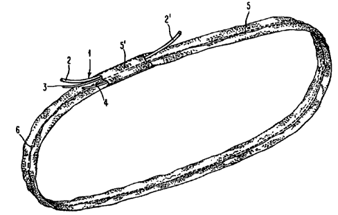
FIG. 1. is an overhead perspective view of an endless
loop twin-path roundsling having an inner lifting core of
7
load bearing strands and an outer protective cover which
shows two free ends (numerals 2 and 21) of a fiber optic
strand (numeral 1) which extend out from the inner core
through the sling cover, and also two free ends (tell tails)
of a load bearing strand (numerals 3 and 4) which extend
through said sling cover.
FIG. 2. is a direct plane view of the endless loop
roundsling of FIG. 1.
FIG. 3. is a cross-section view along the line 3-3 of
the endless loop roundsling of FIG. 2. which shows a free end
of fiber optic strand which separates from the inner core and
extends through the sling cover.
FIG. 4. is a cross-section view of an endless loop
roundsling having twin bundles of inner lifting core of load
bearing strand material inside a single endless tubular
protective cover in which at least one lifting core bundle
comprises at least one fiber optic strand.
FIG. 5. is a cross-section view of an endless loop
roundsling which is similar to the sling of FIG. 4. which
shows a means for fastening and separating said inner core
strand material between two separate outer covers.
DETAILED DESCRIPTION:
The fiber optic signal strand is identified as numeral
1 in Figures 1 through 5 ; it may be used in a single path
roundsling, or in a multiple path roundsling. The drawings
herein illustrate a multiple path roundsling construction.
The two free ends (2 and 21) of the fiber optic strand come
out of the core bundle (numeral 7 in Figure 4) and emerge
through the protective cover (numeral 5 in Figure 2) and
extend outside of the cover for a distance of one inch or
more. The lifting core strands are identified by numerals 7
and 8 in Figures 4 and 5. The protective cover is shown as
a single envelope in numeral 5 of Figure 4, and as part of a
double protective envelope in numerals 10 and 5 in Figure 5.
The protec-tive cover may be fastened to form separate paths
by stitching it longitudinally along its center between the
two separated cores using stitching means as exemplified by
8
_ ~ ~9~~9 3
numeral 6 in Figures 1, 2 and 4, and by using glue or hot
melt adhesive as depicted by numeral 9 in Figure 5.
If desired a sling cover reinforcement and information
patch, which is shown as numeral 5lin Figures 2 and 3, may be
used as a tag on which sling capacity information, and
suchlike may be communicated to the end user. The fiber
optic strand component of the inner core is depicted as
numeral 1 in all the drawings; the two free ends of the fiber
optic signal means strand are depicted as numerals 2 and 21
in Figures 1, 2 and 3. The two free ends of load lifting
strands (tell-tails) are depicted as numerals 3 and 4 in
Figures 1 and 2: an entire bundle of lifting strands which
form a loop core are depicted collectively as numerals 7 and
8 in Figures 3, 4, and 5.
The free ends (2 and 21) of the fiber optic strand
continuity damage signal, and the tell-tail free ends (3 and
4) of the load lifting strands are pulled through openings in
the sling cover 5, as shown in Figures 2 and 3, so that they
extend outside the cover for an inch or more . The roundsling
construction of this invention is formed from loops of
strands of load bearing material as described above which are
bundled together in parallel endless loops to form a load
lifting core, and a loop of fiber optic strand material
having two free ends is incorporated in the endless loop
lifting core; all of the loops are aligned in parallel
relation to each other; the loops are then placed in such
parallel relationship to each other on a surface which has
guide means mounted on the surface; the loops are then
fastened at their distal ends to a holding means; means for
pulling an endless tubular cover having two ends are engaged
to pull the cover over one end of said guide means to
completely envelop the core bundle of endless loops; the
distal ends of the bundle of load core loops are fastened by
suitable fastening means; suitable separating means are used
to separate the free distal ends of the fiber optic strand
from the bundle of lifting core loops; suitable fastening
9
__ _~19~3~~
means are used to fasten the distal ends of the tubular cover
to form it into an endless loop; suitable cutting means are
used to cut an opening or aperture in the cover; and suitable
pulling means are used to pull the two free distal ends of
the fiber optic signal strand through the aperture in the
cover for a distance of one inch or more. A strand of
lifting core material may also be separated from the bundle
of endless loops and converted into a strand having two free
ends which are pulled outside the protective cover to serve
as tell-tail overload signal means.
Various sling constructions can make use of the signal
means disclosed herein to detect overload and core yarn
damage. A skilled artisan will be able to construct slings
which may not be specifically described herein yet still
remain within the scope of the following claims which define
this invention.