Note: Descriptions are shown in the official language in which they were submitted.
~
' CA 02195568 2000-06-16
1
This invention relates to communication apparatus and to a method of operating
such apparatus. It is particularly applicable to the provision of call
services over
communication networks.
Background of the Invention
In today's commerce, companies and organisations often have departments at
widely separated geographical locations. Each geographical location is usually
provided with a private branch exchange, PBX. The PBX connects telephones at
that site to a number of outgoing lines connected to a public network or
private
circuit routes. The private circuit routes allow employees of the company to
communicate with employees at other sites and to use call services as desired.
It has been found desirable for personnel in the different departments to have
available to them a range of call services on their telephone networks. These
services may include "call-back-when-free", "call-back-when next used",
"divert-
on-busy" and "centralised-operator".
The call service "call-back-when-free" is a service which caters for the
situation
where a first telephone user wished to contact a second telephone user but is
unable to do so because the second telephone user is engaged on another call.
The first telephone user dials a code number for the "call-back-when-free"
call
service and replaces his handset. This causes his telephone to ring when the
second telephone user finishes his present call and replaces his handset. By
lifting
his handset, the first telephone user can then cause the second user's
telephone to
ring and the call can then be made.
The call service "call-back-when-next-used" is a call service which caters for
the
situation where the first telephone user attempts to contact the second user
but
although a ringing tone is heard the second user does not answer the
telephone.
WO 96/04754 ~ , ~ ~ PCT/GB95/01639
2
The first user then enters a code for this service and replaces his handset.
This
causes a "registration" of the request for call-back-when-next-used at the PBX
serving the second user's telephone. The PBX monitors the second user's
telephone for activity. When a call is made by the second user and then
cleared
from his telephone, the PBX notifies the PBX serving the first user's
telephone.
The PBX serving the first user's telephone then sets up a "no-ring" call which
establishes a speech path between the two telephones. Only the first person's
telephone is made to ring. When the first user answers his telephone, the
second
user's telephone is made to ring and the call is established.
The calf service "divert-on-busy" caters for the situation where the first
telephone
user wishes to contact the second telephone user but that user is engaged. The
second telephone user may have programmed his telephone system to divert calls
to a colleague's extension when he is engaged on a call.
The call service "centralised-operator" allows one telephone extension of a
local
telephone network to act as the operator on behalf of other extensions of the
entire private telephone network.
Figure 1 shows a conventional communications network topology in which the
network comprises four private branch exchanges 1 to 4, a public switched
telephony network 5 and communication paths 6 to 12.
The private branch exchanges (PBX) 1 to 4 serve local telephone networks at
various sites of the same company. It will be readily appreciated from the
figure
that there are a number of possible routes for calls routed from one local
telephone
network to another along communication paths 6 to 12.
For example, suppose a call originating from a local telephone network served
by
PBX2 is to be routed to a local telephone network served by PBX3. It may be
routed via communication path 8, the public switched network 5 and
communication path 10 to arrive at PBX3. Alternatively, the call may be routed
via communication path 9 to arrive at PBX3. This route is called a private
circuit
Z 195568
3
because it does not involve the call being carried over the public switched
network
5.
In a similar manner, calls may be routed from PBX4 to PBX2 by means of
communication path 1 1, the public switched network 5, and communication path
8. Alternatively, a private circuit may be used, comprising communication path
12, PBX3 and communication path 9, to arrive at PBX2.
Current PBX designs accept calls from an associated network of telephones at
that
site governed by a first communication protocol and pass that call to the
public
network by means of a second protocol. An example of the first protocol is
digital
private network signalling system (DPNSS) and an example of the second is
digital
access signalling system No2 (DASS2). DPNSS is a protocol which has been
designed to support call services but the DASS 2 protocol does not support
call
services.
Private circuit routes allow the PBXs to communicate using the first protocol
DPNSS and hence allow supplementary services. For geographically distant
sites,
it is usual for the organisation to rent a dedicated communication path from a
telephone service provider. In this case the dedicated communication path is
path
9. However, generally speaking, these paths are often underutilised and this
is
especially the case for primary rate 2.048 Mbit/s paths. This results in the
company or organisation having to pay for dedicated communication paths which
can carry a greater volume of call traffic than the company generates.
International Patent Application W093/15583 discloses a communications network
arrangement comprising a first communications network ("public network") which
operates in accordance with a first signalling protocol, and a plurality of
further
communications networks ("PABXs") which are connected to the first
communications network and which belong to the same virtual private network.
The further communications networks operate in accordance with a second
signalling protocol (which may be different far different ones of the further
communications networks) which supports a call service which is not supported
by
' CA 02195568 2000-06-16
4
the first protocol. Each PABX is provided with an "interworking unit" which
sits
longside the PABX providing the virtual network to the PABX. All private
network
calls route through the interworking unit which uses a database to translate
the
incoming private network number to a public network number and establishes an
outgoing call to that public network address across another private interface.
This
is routed back through the PABX so that the public network interfaces that are
required on the PABX can be used. The address provided on the secondary call
identifies the call, but need not route the call to the final extension across
the
public network. The signalling necessary to establish the final part of the
call on
the other side of the network is sent through an overlay network, for example
an
X.25 network. Calls are established within the X.25 network as required to
support the private network. Thus dedicated private circuit functionality is
provided using separate signalling and transmission network bearers.
Summary of the Invention
According to a first aspect of the invention there is provided communication
apparatus for transmitting calls generated by a first communication network
over a
second communication network to a third communication network, the first
communication network operating in accordance with a first communication
protocol which enables call services, the third communication network
operating in
accordance with a communication protocol which enables at least one of the
call
services enables by the first communication protocol and the second
communication network operating according to a second communication protocol
different to the first, which apparatus comprises:
means to produce a call compatible with the second communication protocol;
means to transmit the call over the second communication network to the third
communication network;
said apparatus being characterised by:
CA 02195568 2000-06-16
means to produce a data message compatible with the second communication
protocol, said data message being indicative of the required service; and
means to transmit the data message over the second communication network to
S the third communication network.
The invention thus enables the establishment of call services across a
communication network that need not itself operate according to a
communication
protocol that provides call services. All that is required is that protocol
allows
the transmission of data representing the service required which can then be
read
by an element of the destination network. Thus, it is not necessary for a
dedicated communications network to be provided between two geographically
remove sites of the same organisation. A public switched network, for example;
can be used to carry call service information in a transparent way. This is
less
expensive to the user then using private circuits. In accordance with the
invention
only one protocol is required to carry the call and information required to
set up a
call service.
Preferably, the apparatus further comprises means to receive data messages
from
the second communication network and means to read the data messages to
determine the required data service and to transmit a message to the first
communication network according to the first protocol that enables the
required
service to be established.
The communication protocols may include DPNSS for the network protocol
enabling call services and DASS2 for the protocol operating on the second
network.
According to a second aspect of the present invention there is provided
communications network comprising:
a first communication network operating in accordance with a first
communication
protocol which enables call services;
' CA 02195568 2000-06-16
6
a second communication network operating according to a second communication
protocol different to the first; and
a third communication network operating in accordance with a communication
protocol
S which enables at least one of said call services;
said network being characterised by:
first communication apparatus according to the first aspect of the present
invention;
second communicating apparatus according to the first aspect of the present
invention;
wherein:
said first communication apparatus is arranged in operation to route calls
originating
from the first communication network over the second communication network to
said
second apparatus; and
said second communication apparatus is arranged to accept such calls and to
route
them to an appropriate element of the third communication network.
Preferably, the first protocol is DPNSS and the second DASS1 or DASS2 with the
message being transmitted over the network as a user-to-user message enabled
by
DASS1 or DASS2.
According to a third aspect of the invention there is provided a method of
operating
communication apparatus in a communications network, said communications
network
comprising a first communication network operating in accordance with a first
communication protocol which enables call services and a second communication
network operating according to a second communication protocol different to
the first,
said method comprising the steps of:
CA 02195568 2000-06-16
6a
receiving a call configured according to said first communicating protocol
which call
requires a call service;
generating a call compatible with said second communications protocol;
transmitting said generated call over said second communications network;
said method being characterised by:
configuring one or more data messages including data representative of the
call
service, said data messages being compatible with said second communications
protocol, and
transmitting the or each data message over said second communications network.
Description of the Drawings
A specific embodiment of the invention will now be described, by way of
example
only, with reference to the drawings in which;
Figure 1 shows in schematic form a prior art communications network of a
number
of private branch exchanges interlinked by dedicated lines and a public
switched
network;
Figure 2 shows in schematic form a communications network in accordance with
the
invention;
Figure 3 shows a Virtual Private Network Server which is included in the
network
of Fig. 2;
Figure 4 shows a memory structure stored in a memory of the VPN server shown
in
figure 3;
CA 02195568 2000-06-16
6b
Figure 5 shows a User to User Data Message (UUD) compatible with a protocol
used in the communications network shown in figure 2; and
Figure 6 and 7 are explanatory diagrams.
Detailed Description
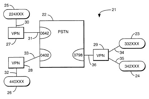
With reference to figure 2, a communication network 21 in accordance with the
invention comprises a public switched telephony network 22, four PBXs 23, 24,
25 and 26 each PBX serving an associated local network (not shown) and three
virtual private network servers VPN server 27, VPN server 28 and VPN server
29.
WO 96/04754 L y ~ 6 8 PCT/GB95/01639
7
The communication network 21 also includes a number of communication paths.
Communication path 30 links PBX25 to the VPN server 27 whilst communication
path 31 links the VPN server 27 to the PSTN 22. Similarly, communication path
32 links PBX26 to VPN server 28 and communication path 33 links VPN server 28
to the PSTN 22. It will be seen from figure 2 that VPN server 29 is linked to
two
PBXs. Communication path 34 links the VPN server 29 to PBX 23 whilst
communication path 35 links the VPN server 29 to PBX 24. A further
communication path 36 links VPN server 29 to PSTN 22.
Each of the local networks includes equipment of a well known type such as
telephones, facsimile machines, computers and computer modems and these will
not be described in greater detail.
The communication paths comprise optical fibre but may comprise other
communication cable.
The PBXs are Meridian 1 private branch exchanges, made by Northern Telecom,
and available from British Telecommunications plc of 81 Newgate Street,
London.
Each VPN server 27, 28, 29 is an intelligent switching unit capable of
signalling
protocol conversion and signalling protocol manipulation in a way which will
be
later described. The VPN servers 27 and 28 are nominally identical, the
structure
is as shown schematically in figure 3 and it comprises four major components,
a
processor 40, a call transceiver 41, a memory 42, and a processor instruction
means 45.
For VPN server 28, the call transceiver 41 receives calls on communication
path
32 originating from PBX 26 and on path 33 calls arriving by way of the PSTN
22.
Calls are also redirected by the call transceiver 41 onto these paths under
the
control of the processor 40. Similarly, for VPN server 27 calls are received
by its
transceiver 41 on paths 30, 31 and calls can also be redirected onto these
paths.
195568 .. :: .:
8
VPN server 29 differs from VPN servers 27,28 only in the connection of a
further
communication path, that is to say, communication paths 34, 35 and 36 are
connected to its call transceiver 41.
The call transceiver 41 is connected to the processor 40 by a control and data
bus
44. The processor 40 is able to interpret call information received by the
call
transceiver 41 and to instruct the call transceiver 41 to retransmit the call
onto an
appropriate one of the paths. The call information is passed by the call
transceiver
41 along the control and databus 44 to the processor 40. The same control and
databus 44 carries the instructions from the processor 40 to call transceiver
41.
The memory 42 stores a database of routing data and corresponding dialled
digit
strings arranged as a set of look-up tables. The processor 40 can access the
data
stored in the look-up table by means of a databus 43 in a way that will be
later
described. The processor instruction means 45 is a data storage area which
stores
the instructions which the processor 40 follows to perform the required
operations.
It takes the form of a ROM (read only memory), but it could take the form of a
floppy disk, hard disk or other data storage device.
Figure 4 shows a table 46 which is held in the memory 42 of each VPN server
27,
28 and 29. The table 46 comprises a first field 46a within which is stored
lead
digits of digit strings that may be dialled by a telephone user. The lead
digits
include "9", "22", "33", "34" and "44".
A second field 46b contains full bearer call numbers to be associated with the
dialled lead digits. Lead digit "9" is associated with null bearer call
number. Lead
digits "22" are associated with a bearer call number "0642-224694". Lead
digits
"33" are associated with a bearer call number "0798-332040". Lead digits "34"
are associated with a bearer call "0798-342041 ". Lead digits "44" are
associated
with a bearer call "0402-440103".
WO 96/04754 j ~ '~ ~ ~ ~ g PCT/GB95/01639
9
Table 46 is configured as a look-up table such that inputting a lead digit or
digits
returns a bearer call number. Thus, if the lead digits "33" are input into the
table
46 the bearer call number "0798-332040" is returned.
As can be seen from figure 2, numbers are allocated to parts of the
communications network 21 as follows.
VPN server 27 is allocated the number "0642 224694" and PBX25 is allocated the
number "224" the extensions supported by the PBX 25 being represented by
"XXX" in the figure.
VPN server 28 is allocated the number "0402 440103" with the PBX it serves PBX
26 being allocated "440". Again, extensions being supported by the PBX are
indicated as allocated to the number range "XXX".
VPN server ~ ~~ is allocated the numbers "0798 332040" and "0798 342041 ".
The PBx _~ is allocated the number "332" with its extensions being allocated
numbers in s range represented by "XXX" in the figure. The PBX 24 is allocated
the r~umoer "342" with the extensions it supports being allocated numbers in a
range represented in the figure by "XXX".
The local networks operate in accordance with a communications protocol called
DPNSS-1 (digital, private network signalling system). This protocol is well
known
to those skilled in the art of telecommunications and it enables a number of
call
services such as "call-back-when-free", "call-back-when-next-used", "divert-on-
busy" and "centralised-operator"
The PSTN 22 operates in accordance with a communications protocol called DASS
2 (Digital Access Signalling System No.2l. Again, this protocol is well known
to
those skilled in the art of telecommunications, but it is important to note
that it
does not support call services. It does, however, allow signalling between two
PBX nodes in the form of user to user data messages.
J 1 ~~568
,0
The user to user data message has a format as shown in figure 5. It comprises
a
thirty two byte structure 50. A first one byte 51 is the MESSAGE TYPE field of
the message. It signifies whether the data message is complete or incomplete.
This caters for the situation where a number of data messages are required to
carry a particular set of data. A first to a penultimate data message will
have a
first byte 51 signifying the data message is incomplete and the last data
message
will have a first byte 51 signifying that the data message is complete. A
second
byte 52 signifies the length of the data carried in a data field 53. The data
field 53
is allocated thirty bytes of the message.
The communications network 21 operates in a manner as shown in figure 6 when
a call is to be established between extensions served by different PBX's. In
the
figure a prefix P1 means that the message is configured according to the first
protocol, DPNSS, and a prefix P2 means that the message is configured
according
to the second protocol DASS2.
Let us suppose that a first user is on an extension served by PBX 24 and
wishes to
call a second user on an extension served by PBX25. The first user dials a "9"
for
an outside line followed by "0642 224XXX" the PSTN number for a direct
connection to the extension (direct in the sense that it does not go via a
switchboard operator).
The dialling of a "9-0642 224XXX" results in a message P1_CALL (9-0642
224XXX) being sent to VPN server 29 from PBX 24. The VPN server 29 receives
this along communication path 35. The call transceiver 41 passes the message
to
the processor 40. The processor 40 inputs the leading digit 9 into the look-up
table 46 held in memory 42. The look-up table returns the bearer call number,
which in this case is null. The processor 40 thus instructs the call
transceiver 41
to suppress the leading digit "9" and a call message according to the DASS2
protocol, P2 CALL (0642 224XXX), is sent over the PSTN22 to VPN server 27.
VPN server 27 converts this message to its equivalent in DPNSS P1_CALL (0642
224XXX).
~1955b8
11
PBX25 then sends an acknowledgement message P1 ACK to the VPN server 27.
VPN server 27 transmits an acknowledge message P2 ACK over the PSTN22 to
VPN server 29. VPN server 29 then sends a P1 ACK to PBX24.
PBX25 then sends a P1 ANSWER message which results in VPN server 27
sending a P2 ANSWER over PSTN22 to VPN server 29. VPN server 29 sends a
P1 ANSWER message to PBX24.
Speech communication between the two extensions can then be initiated.
Figure 7 shows the messaging sequence that occurs when a call service is to be
utilised over the PSTN22 between extensions served by different PBXs. Suppose
a call is to be made from a first extension served by PBX25 to a second
extension
served by PBX23, and then is to utilise a call service. Again in this figure
the
prefix P1 is attached to a message which conforms to the protocol DPNSS and
the
prefix P2 is attached to a message which conforms to the protocol DASS2.
To set up the call, the PBX25 receives a dialled digit string including a code
for a
call service from the first extension. PBX25 then sends a mPSSanP tn VPN
cPrvAr
27, P1_CALL (SERVICE + 332XXX), 332XXX being the second extension served
by PBX23. SERVICE being a code for the particular call service required.
VPN server 27 receives the message and inputs the first two digits "33" of the
extension number into its look-up table 46. This returns the bearer call
number
0798-332040. The processor 40 transmits from the call transceiver 41 a message
P2_CALL (UUD + 0798-332040). The message is transmitted across the PSTN22
to VPN server 29. VPN server 29 sends an P2 ACK acknowledgement message
across the PSTN22 to VPN server 27. This is followed by a P2 ANSWER
message.
The VPN server 27 then sends the original call message P1 CALL (SERVICE +
332XXX) in a UUD in the DASS2 protocol. This is shown in figure 7 as the
message P2_UUD (P1-CALL(SERVICE + 332XXX)). This travels across the
1 X5568 _
12
PSTN22 to the VPN server 29 in a "transparent" way that is to say no number
translation or protocol conversion is carried out but rather the original
message is
carried within the DASS2 compatible UUD.
The processor 40 of VPN server 29 then removes from the UUD, the DPNSS
message P1 CALL (SERVICE + 332XXX). It then transmits the message to
PBX23. Thus it will now be seen that to PBX23 it appears that it has received
the
message directly from PBX25 that is to say it is a DPNSS call.
PBX23 then returns an acknowledgement message P1 ACK followed by
P1 ANSWER. These are loaded by the VPN server 29 into UUDs to form P2 UUD
(P1 ACK) and P2_UUD (P1 ANSWER) and they are sent over the PSTN22 to VPN
server 27. VPN server 27 then removes the DPNSS messages and sends them to
PBX25. Speech can then be initiated.