Note: Descriptions are shown in the official language in which they were submitted.
r"
1
2195613
HT-200
LADDER ANODE FOR CATHODIC PROTECTION OF STEEL
REINFORCEMENT IN ATMOSPHERICALLY EXPOSED CONCRETE
BACKGROUND OF THE INVENTION
1. Field of the Invention
,~~ _
This invention is directed to anodes in the form of a grid for use in
cathodic protection systems.
2. Description of Related Prior Art
Cathodic protection of metal structures, or of metal containing
structures, in order to inhibit or prevent corrosion of the metal in the
structure is well known by use of impressed current cathodic protection
systems. In such systems, counter electrodes and the metal of the structure
are connected to a source of direct current. In operation the metal of the
structure, such as a steel reinforcement for a concrete structure, is
cathodically polarized. The steel reinforcement becomes cathodically
~15 polarized being spaced from the anodically polarized electrode and is
inhibited against corrosion. While cathodic protection is well known for
metal or metal containing structures such as in the protection of offshore
steel drilling platforms, oil wells, fuel pipes submerged beneath the sea, and
in the protection of the hulls of ships, a particularly difficult problem is
presented by the corrosion of steel reinforcement bars in steel-reinforced
concrete structures. Most Portland cement concrete is porous and allows the
passage of oxygen and aqueous electrolytes. Salt solutions which remain in
the concrete as a consequence of the use of calcium chloride to lower the
freezing point of uncured concrete or snow or ice melting salt solutions
which penetrate the concrete structure from the environment can cause more
-1-
~.
' 2195613
rapid corrosion of steel reinforcing elements in the concrete. For example,
concrete structures which are exposed to the ocean and concrete structures
in bridges, parking garages, and roadways which are exposed to water
containing salt used for deicing purposes are weakened rapidly as the steel
reinforcing elements corrode. This is because such elements when corroded
create local pressure on the surrounding concrete structure which brings
about cracking and eventual spalling of the concrete.
Impressed current cathodic protection systems are well known for the
protection of reinforced concrete structures such as buildings and in road
construction, and, particularly, in the fabrication of supports, pillars,
cross-
beams, and road decks for bridges. Over the years, increasing amounts of
common salt, sodium chloride, have been used during the winter months to
prevent ice formation on roads and bridges. The melted snow or ice and
sodium chloride in aqueous solution tend to seep into the reinforced
concrete structure. In the presence of chloride ion the reinforcing steel
rebars are corroded at an accelerated rate such that the resultant corrosion
products formed by the oxidation reaction occupy a greater volume than the
space occupied by the reinforcing bars prior to oxidation. Eventually an
increased local pressure is created which brings about cracking of the
concrete , and eventual spalling of the concrete covering the reinforcing
members so as to expose the reinforcing members directly to the
atmosphere. The use of a valve metal without an electrocatalytically active
coating thereon as an anode in a cathodic protection system is unexpected
in view of the belief among those skilled in the art that a titanium anode or
an alloy of titanium possessing properties similar to titanium cannot be used
in an electrolytic process as the surface of the titanium would oxidize when
anodically polarized and the titanium or alloys thereof would soon cease to
function as an anode.
HT-200 _ 2 _
' 219563
For instance, in U.S. 5,334,293, electrocatalytically coated anodes of
titanium or an alloy of titanium are disclosed for use in an electrolytic
cell,
particularly, for use as an anode in an electrolytic cell in which chlorine is
evolved at the anode. The coating utilized usually includes a metal of the
platinum group, oxides of metals of the platinum group, or mixtures of one
or more metals such as one or more oxides or mixtures or solid solutions of
one or more oxides of a platinum group metal and a tin oxide or one or
more oxides of a valve metal such as titanium. Similar electrocatalytically
coated titanium electrodes are disclosed in U.S. 3,632,498; U.S. 5,354,444;
and U.S. 5,324,407.
Known methods of introducing an anode into existing concrete
structures may involve insertion of an anode into a slot cut into the
concrete.
After application of the anode a cap of grout is applied to backfill the slot.
Representative anodes for cathodic protection of steel reinforced concrete
structures are disclosed in U.S. 5,062,934 to Mussinelli in which a grid
electrode comprised of a plurality of valve metal strips having voids are
disclosed. Another type of anode strip for cathodic protection of steel
reinforced concrete structures is disclosed in Canadian 2,078,616 to Bushman
in which mesh anodes are disclosed consisting of an electrocatalytically
coated valve metal which is embedded in a reinforced concrete structure so
as to function as the anode in a cathodic protection system. In U.S.
5,031,290 a process is disclosed for the production of an open metal mesh
having a coating of an electrocatalytically active material formed by fitting
a sheet and stretching the coated sheet to expand the sheet and form an
open mesh. In U.S. 4,401,530 to Clere, a three dimensional electrode having
substantially coplanar, substantially flat portions, and ribbon-like curved
portions is disclosed for use as a dimensionally stable anode in the
production of chlorine and caustic soda. The ribbon-like portions of the
HT-200 _ 3
2195613
anode are symmetrical and alternate in rows above and below the flat
portions of the anode.
In U.S. 3,929,607 to Krause, an anode assembly for an electrolytic cell
is disclosed comprising a film-forming metal foraminate structure comprising
a plurality of longitudinal members spaced with their longitudinal axis
parallel to one another and carrying on at least part of their surface an
electrocatalytically active coating. Each longitudinal member comprises a
channel blade member constituted by a pair of parallel blades having one or
more bridge portions connected to the current lead-in means.
It is known from U.S. 5,334,293 that a titanium anode cannot be used
in an electrolytic cell, particularly in an electrolytic cell in which during
operation of the cell chlorine is evolved at the anode. Such an anode
cannot be used in this electrolytic cell as the surface of the titanium anode
would oxidize when anodically polarized and the titanium would soon cease
to function as an anode. Coatings comprising ruthenium oxide are disclosed
as useful on a titanium substrate to obtain an electrode having a
commercially useful lifetime.
Bockris et al. in Modern Electrochemistry, volume 2, pages 1315 - 1321,
Plenum Press, explains the transformation of a metal surface from a
corroding and unstable surface to a passive and stable surface as being
facilitated by increasing the electrical potential in the positive direction
on
the metal. As the potential is increased, the current initially increases,
reaching a maximum value and then starts sharply to decrease to a negligible
value. The point at which the current sharply decreases is referred to as
passivation and the potential at which this occurs is termed the passivation
potential.
HT-200 _ 4 _
219563
In the prior art, electrodes particularly for use in cathodic protection
systems require electrocatalytic coatings on valve metals which are subject to
passivation in order to overcome the tendency of such metals to passivate
and cease to function as electrodes. Such coatings are described in U.S.
3,632,498 as consisting essentially of at least one oxide of a film-forming
metal and a nonfilm-forming conductor the two being in a mixed crystal
form and covering at least two percent of the active surface of the electrode
base metal. Similarly, electrodes made utilizing a valve metal substrate are
disclosed as requiring one or more layers of a coating containing platinum
as disclosed in U.S. 5,290,415 and U.S. 5,395,500.
An anode useful in a cathodic protection system to protect the
reinforcing steel bars in a concrete structure can consist of a porous
titanium
oxide, TiOx where "x" is in the range 1.67 to 1.95, as disclosed in European
patent application 186 334 or where "x" is in the range 1.55 to 1.95, as
disclosed in U.S. 4,422,917. Other porous materials are disclosed in 186 334
as substitutes for the porous titanium oxide such as graphite, porous
magnetite, porous high silicon iron or porous sintered zinc, aluminum or
magnesium sheet.
In U.S. 4,319,977, an electrode formed of thin sheets of titanium is
disclosed as useful in an electrometallurgical cell. In addition to a metal
such as titanium, electrodes consisting essentially of tantalum, niobium, or
zirconium are disclosed as useful in the British patent no. 951,766 cited in
this United States patent. As described in '977, the titanium electrode is
utilized as an anode in a method of electrolytically producing manganese
dioxide by immersing the electrode in a solution of manganese sulphate and
sulfuric acid and electrolytically depositing the manganese dioxide onto the
electrode. Periodically, the manganese dioxide is removed from the
electrode.
HT-200 _ 5 _
2i9~bi3
Expanded mesh anode structures having an electrocatalytic surface
which are disclosed as useful for cathodic protection of steel reinforced
concrete are disclosed in U.S. 5,421,968, U.S. 5,423,961, and 5,451,307.
These mesh anode structures have 500 to 2000 nodes per square meter
formed at metal strand intersections in the mesh and can be supplied in roll
form. Upon application to a concrete surface in order to present corrosion
of steel reinforcing structures therein, the expanded metal mesh is connected
to a current distribution member such as by welding.
A grid electrode is disclosed for use in cathodic protection of steel
reinforced concrete structures and a method of forming a grid electrode are
disclosed, respectively, in U.S. 5,062,934 and U.S. 5,104,502. The metal
members forming the grid electrode comprise a plurality of expanded valve
metal strips with voids therein, at least 2000 nodes per square meter formed
by intersecting strands of expanded metal, and an electrocatalytic surface
thereon. The valve metal strips forming the electrode grid are welded
together to form the grid. In use, a current distribution member is also
connected at intervals to the electrode grid.
SUMMARY OF THE INVENTION
Disclosed are novel valve metal grid electrodes for operation at either
high or low current density, particularly, as grid anodes in a cathodic
protection system in which iron or steel rods are embedded in a concrete
structure or as grid anodes for the cathodic protection of steel pipelines
placed in sea water, saline muds, or in the ground. The steel rods or
pipelines are protected against corrosion by connecting the novel valve metal
grid anodes and the iron or steel pipelines or reinforcing rods in the
concrete structure to an electrical circuit and impressing a current
sufficient
to cause the iron or steel material to act as a cathode in the circuit. The
HT-200 _ 6 _
i I i I
CA 02195613 2005-03-17
71932-105
valve metal anode strips which are spaced apart to form the
grid electrode can be porous or non-porous, coated with an
electocatalytically active metal or non-coated, and of any
shape, for instance, expanded metals, slit and deformed metal
strips, rods, tubes, etc.
Thus this inventor seeks to provide a grid
electrode for cathodic protection of a steel reinforced
concrete structure comprising a plurality of valve metal
strips spaced apart, said strips forming nodes at the
intersections of said strips, said nodes being present in the
amount of less than 100 nodes per square meter, said strips
being electrically connected at the intersections thereof to
form a grid, and said grid electrode further comprising a
plurality of electric current-carrying metal members
consisting of a valve metal, spaced apart and extending
across at least two valve metal strips.
This inventor also seeks to provide a concrete
structure comprising a cathodic protection grid electrode in
steel reinforced concrete, said electrode comprising a
plurality of valve metal strips, said strips forming nodes at
the intersections of said strips, said nodes being present in
the amount of less than 100 nodes per square meter, and said
strips being electrically connected at the intersections to
form a grid, and said grid electrode further comprising a
plurality of electric current-carrying metal members
consisting of a valve metal, spaced apart and extending
across at least two of valve metal strips of said grid
electrode.
This inventor also seeks to provide a method of
forming a grid electrode cathodic protection system for
cathodically protecting a steel reinforced concrete structure
comprising applying to a surface of said steel reinforced
-7-
i ~ i
CA 02195613 2005-03-17
71932-105
concrete structure a grid electrode comprising a plurality of
strips consisting of a valve metal., said strips forming nodes
at the intersections of said strips, said nodes being present
in the amount of less than 100 nocLes per square meter, and
said strips being electrically connected at their
intersections to form said grid electrode, said grid
electrode further comprising a plurality of longitudinally
extending electric current-carrying members consisting of
said valve metal spaced apart fro~~ one another or a plurality
of electric current-carrying members consisting of said valve
metal laterally extending across a.t least two longitudinally
extending strips consisting of said valve metal.
-7a-
CA 02195613 2000-11-30
76561-3
BRIEF DESCRIPTION OF THE DRAWINGS
Figures 1 - 13 illustrate several examples of porous
valve metal strips utilized to form the grid electrode of the
invention shown in Figure 14. Non-porous valve metal strips
can also be used to form the grid electrodes of the invention.
The porous valve metal strips are formed by slitting and
subsequently expanding a valve metal strip in a direction
normal or parallel to the largest dimension of the valve metal
strip. Each of these valve metal strips can be formed into the
grid electrode of the invention by electrically connecting the
valve metal strips at the intersections of the strips.
Alternatively, mixtures of the various examples of valve metal
strips, including non-porous strips can be utilized to form the
grid electrode of the invention.
Figure 1 is a plan view of an example of a portion of
a unitary, multiplane, porous, metal strip or ribbon showing a
plurality of louvers arranged laterally across the metal strip.
Figure 2 is a side view of the metal strip of Figure
1.
Figure 3 is an enlarged side view taken through
section 3-3 of Figure 1.
-7b-
295613
Figure 4 is a plan view of yet another example of a portion of a
unitary, mufti-plane, porous, metal strip showing a series of louver units
oriented on a metal strip in a direction parallel to the longitudinal
direction
of the metal strip and spaced apart from adjacent louver units by a plane
which is intermediate between the planes defined by the upper and lower
lateral extremities of said louvers.
Figure 5 is a side view of the anode of Figure 4.
Figure 6 is an isometric view of the anode of Figure 1.
Figure 7 is an isometric view of the anode of Figure 4.
Figure 8 is a plan view of one example of a portion of a unitary,
mufti-plane, porous, metal ribbon strip showing perforation or slitting of a
metal sheet with openings of predetermined size, shape and arrangement and
bending the slit strips to form trough and crest nodes.
Figure 9 is a cross sectional view of the perforated sheet shown in
Figure 13 showing the appearance on bending the perforated sheet so as to
raise upper, crest and lower, trough nodes in a direction normal to the plane
of the largest dimension of the perforated sheet.
Figure 10 is a plan view of a second example of a portion of a unitary,
mufti-plane, porous, metal strip showing a perforated or slit sheet prior to
bending the rows between perforated sections so as to form a metal ribbon
having a plurality of trough and crest nodes.
HT-200 _ g _
2i 9613
,,,..
Figure 11 is a cross sectional view of a portion of the metal ribbon
subsequent to bending the rows between perforated sections of the ribbon
shown in Figure 10.
Figure 12 is an isometric view of a portion of the porous, metal ribbon
shown in cross section in Figure 11.
Figure 13 is an isometric view of a portion of the metal ribbon shown
in cross section in Figure 9.
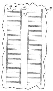
Figure 14 is a diagrammatic representation of two grid anodes placed
upon a concrete surface. Strips forming the grid can be either porous or
non-porous, electrocatalytically coated valve metal or non-coated valve metal.
In other embodiments not shown, the louvers of Figures 2 and 5
extend only above the base plane of the metal anode strip. In addition to
forming the grid electrode of the valve metal strips shown and described
above, the valve metal strips can be formed of non-porous valve metal strips
or of the expanded valve metals shown in the prior art, for instance in U.S.
5,423,961.
DESCRIPTION OF THE PREFERRED EMBODIMENTS
This invention relates, generally, to a cathodically protected concrete
structure, a method of forming a grid electrode cathodic protection system,
and to a grid electrode for use in a cathodic protection system, particularly
for a cathodic protection system to protect a steel reinforced concrete
structure. The grid electrode of the invention is formed of a plurality of
porous or non-porous valve metal strips forming nodes at the intersections
HT-200 - 9 -
219613
of said strips and electrically connected to form a grid such as by welding.
Porous or non-porous electric current-carrying valve metal members
are also spaced apart on the grid electrode and extend across at least two
valve metal strips. The current-carrying valve metal members can extend on
the grid electrode either laterally or longitudinally and can be coated with
an electrocatalytic metal or be uncoated and can be porous or non-porous.
If the current-carrying member is placed laterally and electrically connected
on the grid electrode, it need not be coated but it may be coated. If the
current-carrying member is placed longitudinally on the grid electrode and
electrically connected to the laterally extending cross member metal strips,
it is coated with an electrocatalytic metal.
Non-porous valve metal strips can be used to form the grid electrode
by using valve metal strips either with or without an electrocatalytically
active
metal surface. Non-porous valve metal strips suitably have a thickness of
about 0.010 inches to about 0.030 inches, preferably, about 0.015 inches to
about 0.020 inches, and most preferably, about 0.012 inches to about 0.017
inches. Non-porous valve metal strips suitably have a width, generally, of
about 0.20 to about 0.25 inches or more.
The porous valve metal strips used to form the grid-electrode of the
invention can be formed by slitting and expanding a valve metal ribbon or
strip either in a direction normal to the largest surface or in a direction of
the plane of the largest surface of a valve metal strip. In addition, the
valve
metal grid electrodes can function effectively as anodes in a cathodic
protection system, for instance, to protect steel reinforcement elements in a
concrete structure whether or not the surface of said valve metal has an
electrocatalytically active metal coating. The grid electrodes of the
invention
HT-2(?0 _ 10 -
2195E~ 13
can be manufactured in roll form for ease of handling. Contrary to prior art
grid electrodes, especially of the type in which a valve metal is highly
expanded to form a grid sheet of expanded metal, the grid electrodes of the
invention ca.n be installed without excessive damage to the grid structure by
breakage of the strands of the expanded metal or splitting of the expanded
metal at the expanded metal nodes.
The porous valve metal strips suitably have a longitudinal strip
thickness, generally, of about 0.015 to about 0.030 inches, preferably, about
0.02 to about 0.025 inches and a width, generally, of about 0.15 to about 0.30
inches, preferably, about 0.20 to about 0.25 inches. Laterally oriented porous
valve metal strips, generally, have the same thickness but a preferred
thickness of about 0.0175 to about 0.020 inches and the same width as the
non-porous strips. Alternatively, where a higher current density is required
on the grid anode of the invention either or both longitudinal and lateral
strip widths can be, generally, about 0.2 to about 1.5 inches, preferably,
about 0.75 to about 1.0 inches and, most preferably, about 0.5 to about 1.0
inches.
In one embodiment, a grid electrode is formed from an expanded
valve metal strip which is obtained by slitting a valve metal strip, for
instance, a grade 2 titanium strip and, subsequently expanding the slit strip
in a direction normal to the largest dimension surface of the valve metal
strip. A titanium strip thus formed is considerably stronger, as indicated by
higher tensile strength and hardness levels, than a strip expanded in the
direction of the plane of the largest surface of a grade 1 titanium which is
typically used in the prior art to provide an expanded titanium grid electrode
structure. The grid electrode of this embodiment of the invention will have
a network of nodes having less than about 100 nodes per square meter.
HT-200 - 11 -
i ~ i
CA 02195613 2005-03-17
71932-105
In another embodiment, a valve metal grid electrode
can be formed from strips of an expanded valve metal, which
are expanded in a direction of the plane of the largest
surface, electrically connected at intersecting strips, and
expanded at a typical expansion factor of 10:1 and
preferably 15:1. A substantially diamond shaped pattern is
preferred having about 500 to about 2000 connections per
square meter of expanded valve metal strip. These expanded
valve metals are disclosed in U.S. 5,062,934; U.S. 5,104,502;
U.S. 5,451,307; U.S. 5,423,961; and U.S. 5,421,968. The grid
electrode of this embodiment of the invention will have a
network of nodes formed at the intersections of said strips
having less than about 100 nodes per square meter. In both
embodiments, the grid electrode is formed by electrically
connecting the strips of the grid at the intersections of the
valve metal strips.
The grid electrode contains a plurality of electric
current-carrying valve metal members spaced apart from one
another and, preferably, extending laterally across at least
two valve metal strips which extend in a longitudinal
direction. Generally, the current-carrying valve metal
strips can extend either longitudinally or laterally or both
longitudinally and laterally. The valve metal current-
carrying strips have an electrocatalytic metal surface when
oriented laterally on the grid electrode or can be used to
form the grid electrode of the invention with or without an
electrocatalytically active metal surface when oriented
longitudinally.
Accordingly, each of the valve metal grid
electrodes of the embodiments set forth above can utilize a
valve metal anode without benefit of an electrocatalytic
metal coating thereon.
-12-
CA 02195613 2000-11-30
76561-3
The valve metal strips can be coated with an
electrocatalytic metal coating either before or after forming
into an electrode grid. The grid electrodes of the invention
are capable of being rolled up subsequent to manufacture to
allow ease of transport to a construction site where they are
thereafter unrolled and applied to the surface of a concrete
structure. In those embodiments in which the grid is formed by
the assembly of valve metal strips which have been previously
slit and expanded in a direction normal to the largest surface
area of the strip, the strength and electrical conductivity of
the original valve metal strip before slitting and expansion is
retained. In use, a valve metal current distributing member is
placed at intervals in association with the grid electrode or a
series of adjacent grid electrodes placed on a concrete surface
in a cathodic protection system. The valve metal current
distributing member can be porous or non-porous and have an
electrocatalytically active metal composite coating or can be
uncoated. A series of adjacent grid electrodes on a concrete
surface, generally, will be electrically connected by a current
distributing member. The current distributing member can be
placed laterally at intervals across at least two valve metal
strips or can be longitudinally oriented on the grid electrode.
The number of valve metal strips forming the grid
electrode which are placed in a longitudinal direction in the
grid electrode, generally, is about 1
-13-
. 2i 95613
to about 4, preferably, about 2 to about 3. At least one of the longitudinally
directed valve metal strips can be a current distributing member. The grid
electrodes can be formed in any suitable width, preferably, about 8 inches
to about 30 inches. The void space between lateral valve metal strips in the
grid electrode, generally, can be less than 1 inch up to about 6 inches or
more, preferably, about 2 inches to about 4 inches, most preferably, about
3 inches to about 4 inches. The spacing between adjacent grid electrodes
placed on a concrete surface, generally, is a function of the amount of
current required to cathodically protect the steel reinforcement member in
the concrete. For even current distribution, this spacing can be from less
than 1 inch to about 8 inches, preferably, about 3 inches to about 6 inches,
most preferably, about 3 inches to about 4 inches.
In each of the embodiments of the grid electrode of the invention in
which the valve metal strip is elongated or expanded in a direction normal
to the largest surface area of the strip, the valve metal strips forming the
grid electrode of the invention can be formed of a valve metal such as
titanium using either a grade 1 or grade 2 titanium. In the prior art, the use
of grade 1 titanium has been considered desirable to form an expanded
metal structure which is expanded in a direction of the plane of the largest
surface of the metal strip because of the, generally, greater expansion ratios
utilized to reduce cost and to allow the expansion process to be performed
without excessive breakage of the strands of the expanded mesh. Grade 1
titanium is more suitable for preparing such expanded metals as having a
lower tensile strength as well as a higher purity than grade 2 titanium.
However, the higher cost and reduced availability of grade 1 titanium has
necessitated high expansion ratios in order to provide an economical but
necessarily weaker expanded mesh structure than can be provided by the use
of a grade 2 titanium which is less expensive and more readily available.
HT-200 _ 14 _
2 i 95613
I
The grid anode of one embodiment of the invention is formed of a
valve metal such as titanium or tantalum having an oxide film on the surface
thereof and is formed of porous or non-porous valve metal strips forming
nodes at the intersections of said strips and electrically connected and is
free
of electrocatalytically active metal coatings which have been applied in the
prior art to valve metal electrodes, particularly valve metal substrates for
use
as anodes in cathodic protection systems. The anode grid in this
embodiment of the invention does not require the application of an
electrocatalytic metal coating or a precursor electrocatalytically active
metal
coating and the subsequent activation of said catalytic coating.
Surprisingly, it has been found possible to extend the lifetime of a
valve metal anode grid, as determined by exposure of the anode grid to
accelerated testing, by heating the valve metal anode grid at elevated
temperature. Generally, exposure of the valve metal of the anode grid to
a temperature of about 250°C to about 750°C for a period,
generally, of
about 3 minutes to about 5 hours, preferably, about 30 minutes to about 3
hours, and most preferably, about 1 hour to about 2 hours results in a
substantial improvement in anode grid lifetime, i.e., time before passivation
occurs at a given current density. In use, the grid anode in this embodiment
of the invention is connected to a source of direct current and the circuit is
completed by connecting as a cathode the reinforcing elements, i.e., steel
bars within the concrete structure. The impressed current is opposite and
at least equal to the naturally occurring current which results under normal
circumstances. The net result of impressing a direct current which is
opposite and equal to the naturally occurring current is to prevent
electrolytic corrosion action on the reinforcing steel bars.
HT-200 _ 15 _
2~ 9513
Suitable valve metals include titanium, zirconium, niobium, tantalum,
and alloys comprising one or more valve metals or metals having properties
similar to those of valve metals. Titanium is a preferred valve metal as it
is readily available and relatively inexpensive when compared with the other
valve metals. Preferably, the titanium is ASTM 265 titanium grade 1 or 2.
It is well known that valve metals exposed to normal atmospheric
conditions will inevitably possess a surface oxide layer for example, titanium
oxide (Ti02) which can be stoichiometric or non-stoichiometric depending
upon the conditions of formation of the oxide layer. The valve metal strips
forming the grid anode of the invention are believed to have a surface oxide
layer which is stoichiometric as represented by the compounds Ti02, TiO,
and Ti203. Accelerated tests indicate that the lifetime of the electrode can
be substantially extended by activating the electrode at elevated
temperatures. It is considered that this process results in the formation of
a surface oxide layer which is stoichiometric.
The novel grid electrode can be formed by electrically connecting
intersecting valve metal strips. The grid anodes can be formed of a plurality
of valve metal strips having trough and crest nodes or protrusions defining
upper and lower planes at the extremities of said nodes as shown in Figures
8 - 13. The nodes of the valve metal strip can be spaced longitudinally to
provide an intermediate plane separating the upper and lower nodes. The
trough and crest nodes, in a preferred embodiment, alternate both laterally
and longitudinally. The metal grid anodes of the invention are electrically
connected at intersecting strip areas, such as by welding.
Other shaped valve metal strips can be used as shown in Figures 1 -
7. In addition, valve metal strips of the expanded valve metals shown in the
HT-200 _ 16 _
2195r~i3
prior art, such as those disclosed in U.S. 5,423,961 and non-porous valve
metal strips can be used to form the grid electrodes of the invention.
The use of the valve metal grid anode without an electrocatalytically
active metal surface in a cathodic protection system for reinforced steel
elements in concrete is limited to those applications where the anode current
density is controlled at up to about 20 milliamps per square foot unless the
valve metal is activated by heating at an elevated temperature. Generally,
the grid anodes of this embodiment of the invention can be prepared from
a valve metal such as grade 1 or grade 2 titanium which normally has an
oxide film on the surface thereof. Preferably, a valve metal such as titanium
is activated prior to use as an anode so as to extend the lifetime of the
anode and allow use of the anode at higher anode current densities.
Activation can be accomplished by heating the valve metal anodes at
elevated temperature as previously described. Preferably, activation is
accomplished by exposure of the valve metal grid to a temperature of about
250°C to about 750°C, preferably, for a period of about 3
minutes to about
5 hours. Upon activation a substantial improvement in anode grid lifetime
occurs, as indicated by the time for passivation of the anode grid to occur
at a given anode grid current density. Useful valve metals for forming the
anode grid are selected from the group consisting of titanium, tantalum,
zirconium, niobium, and alloys and mixtures thereof.
Anode grid current densities of up to about 20 milliamps per square
foot can be used with the valve metal grid anode of the invention not coated
with an electrocatalytically active metal coating. Preferably, cathodic
protection systems in which steel reinforcing elements are embedded in
concrete are, generally, operated at an anode grid current density of about
0.1 to about 15 milliamps per square foot, most preferably, an anode grid
current density of about 2 to about 10 milliamps per square foot. As
HT-200 _ 17 _
- 21 ~~6 i 3
indicated above, an extension of the lifetime of the valve metal anode grid
can be obtained by heating the anode. Upon heat activation of the valve
metal anode grid, anode grid current densities of up to about 50 milliamps
per square foot can be used, preferably, about 10 to about 20 milliamps per
square foot.
II
Where the novel grid anode of the invention is formed of strips of a
composite comprising a valve metal base and an electrocatalytically active
metal coating thereon, cathodic protection systems can be operated at
substantially higher current densities such as up to about 80 to about 120
amperes per square foot.
The application of an electrocatalytically active metal coating on the
surface of a valve metal substrate can involve painting or spraying an
aqueous or organic solvent solution of a soluble precursor compound on the
surface of the valve metal. Application of the precursor catalyst compound
can also be made by electrolytic and electroless plating and by thermal
spraying. Thermal spraying is defined to include arc-spraying as well as
plasma and flame spraying. The electrocatalytically active metal can also be
applied by thermal spraying of a metal or metal composite. Subsequent to
application of a precursor compound, the coating is heated to convert the
precursor compound to the electrocatalytically active metal form such as the
oxide. Thermally sprayed coatings may not require heating to convert the
catalytic coating to the catalytically active metal form.
The physical form of the electrocatalytically active metal coated grid
electrode is similar to that described above for the grid electrode not having
an electrocatalytically active metal surface, i.e., valve metal strips having
a
HT-200 - 18 -
2 i ~5~13
plurality of trough and crest nodes, as shown in Figures 8 - 13; valve metal
strips as shown in Figures 1 - 7; expanded metal strips as disclosed in the
prior art and non-porous valve metal strips. Where higher current densities
are used with the electrocatalytically active metal coated grid electrode, it
will be recognized by one skilled in this art that a larger number of anode
strips or thicker or wider anode strips will be used to form the grid
electrode.
Typical catalyst precursor compounds used to apply liquid solution
coatings and thermal spray coatings consist of platinum group metal
compounds selected from the group consisting of metal compounds of
platinum, palladium, ruthenium, rhodium, osmium, iridium, or mixtures or
alloys thereof. Cobalt, nickel, and tin compounds can also be utilized as
electrocatalytic precursor compounds. The precursor compounds are heated
to convert these or a portion of these compounds to their oxides.
It is to be understood that the valve metal strips can be coated with
a composite of a catalytic coating either before or after forming into porous
strips or before or after being assembled in grid form. Usually before
coating, the valve metal will be subjected to a cleaning operating, e.g., a
degreasing operation, which can include cleaning plus etching, as is well
~0 known in the art of preparing a valve metal to receive an electrochemically
active metal coating. The electrochemically active metal coating composite
can be provided from a valve metal and a platinum group metal, oxides of
electrocatalytically active metals, or it can be any of a number of active
oxide
coatings such as the platinum group metal oxides, the oxides of tin, nickel,
manganese, or magnetite, ferrite, cobalt spinet, or other mixed metal oxide
coatings, which have been developed for use as anode coatings in the
industrial electrochemical industry for an oxygen evolution reaction. It is
particularly preferred for extended life protection of concrete structures
that
HT-200 - 19 -
I
the anode coating be a mixed metal oxide, which can comprise a solid
solution of a valve metal oxide and a platinum group metal oxide.
For the extended life protection of concrete structures, the coating
should be present in an amount of from about 0.05 to about 0.5 gram of
platinum group metal per square meter of electrode strip. Less than about
0.05 gram of platinum group metal will provide an insufficient
electrochemically active metal coating for preventing passivation of the valve
metal substrate over extended time, or to economically function at a
sufficiently low single electrode potential to promote selectivity of the
anodic
reaction. On the other hand, the presence of greater than about 0.5 gram
of platinum group metal per square meter of the electrode strip can
contribute an expense without commensurate improvement in anode lifetime.
In this embodiment of the invention, the mixed metal oxide composite
coating is highly catalytic for an oxygen evolution reaction. The platinum
group metal or mixed metal oxides for the coating are such as have been
generally described in one or more of U.S. Patent Nos. 3,265,526, 3,632,498,
3,711,385 and 4,528,084. More particularly, such platinum group metals for
forming the composite include platinum, palladium, rhodium, iridium and
ruthenium or alloys with other metals and the valve metals for forming the
composite include titanium, tantalum, zirconium, niobium, and alloys and
mixtures thereof. Mixed metal oxides comprise at least one of the oxides of
these platinum group metals in combination with at least one oxide of a
valve metal or an oxide of a valve metal and another non-precious metal
such as the oxides of tin, nickel, cobalt, and manganese.
The three-dimensional structure of the expanded valve metal strips
shown in Figures 1 - 13 in use in a concrete structure allows the distribution
of the electrical current in multiple planes in the concrete. To obtain this
three-dimensional current distribution, both the anode grid structure and the
HT-200 - 20 -
~1y5b13
electrical current must not be concentrated in one plane. With a three-
dimensional structure, there is less likelihood of any subsequent delamination
of the usual concrete overlay as a result of the anode presence in the
concrete structure. With the prior art expanded mesh structures, for instance
there is a greater tendency for the concrete overlay to separate from the
underlying concrete.
The distribution of current from the surfaces of the anode to the steel
rebar depends upon the proximity of the anode surfaces to the rebar. If the
anode grid is placed between two mats of steel rebar, then the current will
emanate, generally, from both sides of the anode strands, and particularly
from the surfaces in the planes of the crest and trough nodes of the anode
strips of Figures 8 - 13 or the planes defined at the upper or upper and
lower louver surfaces of the anode strips of Figures 1 - 7. The amount of
current emanating from these surfaces will tend to be greater than the
amount of current emanating from the essentially flat expanded metal grid
anodes of the prior art in which the current from the plane of the expanded
mesh structure emanates equally from the crossing and connecting strands;
that is, the current would tend to be more evenly distributed.
When the valve metal strips forming the grid electrode of the
invention are characterized by a plurality of louvers, as shown in Figures 4,
5, and 7, arranged in multiple louver units and aligned in the long dimension
substantially parallel in a longitudinal direction of the metal strip from
which
they are formed, each louver defines upper or upper and lower planes at the
lateral extremities of said louvers. Multiple louver units are spaced from
adjacent units by an intermediate plane. A series of multiple louver units
aligned as indicated above have the same or alternating angles of about
20°
to about 90° to said intermediate plane. In addition to the parallel or
perpendicular alignment of the louvers in the long dimension in a
HT-200 - 21 -
2~ 9613
longitudinal direction of the metal strip, as shown in Figures 4 and 1,
respectively, the louvers can be oriented on the metal strip at any angle
between 0 and 90° to the longitudinal direction of the metal strip.
When the valve metal strips forming the grid electrode of the
invention are characterized by a plurality of substantially parallel louvers,
as
shown in Figures 1 -3, and 6, and aligned in a lateral direction on said metal
anode strip, each louver can define upper and lower planes at the extremities
of said louvers. Said louvers are bordered at their lateral extremities by an
intermediate plane. The strips are, generally, formed using an
electrocatalytically active metal coated valve metal. The strips can also be
coated with an electrocatalytically active metal after forming or after a grid
structure bonded at the intersections of said metal strips is formed. Where
the valve metal is coated with an electrocatalytically active metal layer, it
is
preferred that the coating comprise a mixed oxide of a platinum group metal
and a valve metal or an additional platinum group metal, as set forth above.
In the example of a valve metal strip shown in Figure 7, the valve
metal strip is characterized by a plurality of louvers arranged in multiple
louver units and aligned in the long dimension substantially parallel to the
longitudinal direction of the metal strip. The louvers can define upper and
lower planes at the lateral extremities of said louver units. The louver units
are spaced from adjacent louver units by an intermediate plane. In another
example shown in Figure 6, the valve metal strip is a plurality of
substantially parallel louvers aligned laterally in the long direction on the
strip. The grid anode is formed with said strips, said louvers defining either
upper or upper and lower planes at the lateral extremities of said louvers.
Said louvers are bordered at their lateral extremities by an intermediate
plane.
HT-200 _ 22 _
21~~613
While each of the examples of valve metal strips described above in
Figs. 6 and 7 are useful, it is preferred to utilize the example shown in Fig.
7 so that electrical conductivity along the valve metal strip will not be
compromised or at least reduced very little. Orienting the louvers of the
valve metal strip laterally as in the example of Fig. 6 is less desirable with
respect to electrical conductivity of the anode.
In another example not shown in the Figures, the multiple louver units
define only an upper plane at their upper extremity; the lower extremity
coinciding with the plane of the metal strip from which the anode is formed.
The openings formed by the louvers of these valve metal strips are
large enough to allow a concrete grout to flow through such openings.
Preferably, a minimum opening formed by the louvers is about 1/16 of an
inch in dimension, more preferably, about 3/32 of an inch to about 1/8 of an
inch. On the other hand, the louvers are not so large that, when they are
formed by twisting the louver slats out of the plane of the starting strip of
metal, they do not form a plane or planes which extend so as to be
inadequately covered in use by the usual concrete overlay. Preferably, the
anode grid profile when viewed from the side is less than about 1/2 inch.
The length of the louvers of the valve metal strips is less critical than
the dimensions set forth above. Generally, the length of the louvers can be
about 1/2 inch to more than 3 or 4 inches in the embodiment of Fig. 7
depending somewhat upon the width of the anode strip. Giving due
consideration to the width and thickness of a particular louver slat, the
length of the louver slat is not so great that the rigidity of the valve metal
strips is compromised, that is, not so great that the valve metal strips would
not retain the original orientation under normal handling or installation
procedures. In addition, the length of the louver slat, if oriented along the
HT-200 - 23 -
2~ 95613
length of the starting anode strip, as in the embodiment of Fig. 7, is not so
great that upon rolling up the louvered anode, an inordinately large diameter
roll would result. Most preferred dimensions of the anode are an anode
strip having a width of about 3/4 inch, about 0.020 inches in thickness having
louvers about 1 to about 1-1/2 inches long and about 3/32 of an inch to
about 1/8 of an inch wide for the embodiments of Fig. 7.
The louvers of Figures 1 - 7 are formed by slitting a strip of valve
metal, then twisting the slit strips into final orientation so as to form an
angle with the base plane of the anode strip from which it is formed in
which the angle of the louvers is at least about 20°C to the plane of
the
original anode strip, preferably, at least about 70° to about
90°C to said
plane. The louvers can be oriented so that succeeding groups of louvers are
turned in an alternate direction or the louvers can all be oriented in the
same direction.
With respect to the example of the valve metal strip of Fig. 7, the
louvers define either upper or upper and lower planes at the lateral
extremities of said louvers. Intermediate between the upper and lower
planes is the original base plane of the valve metal strip. The base or
intermediate plane separating the series of louver groups can vary in
longitudinal dimension but in order to maintain the ability of the valve metal
to accommodate the penetration of concrete grout and to increase the
effective valve metal surface area, the intermediate plane, generally, is not
more than about 2 inches in longitudinal dimension, preferably, less than 1
inch in longitudinal dimension, and, most preferably, about 3/8 of inch to
about 1/4 of an inch in longitudinal dimension.
The anode grid strips can be formed using conventional metal working
equipment such as a piercing die to perforate the metal strip in preselected
H'T-200 _ ~ _
2195613
portions and a die mechanism to impart the final shape to the louvers which
can project both above or both above and below the base plane of the metal
strip from which the grid anode is formed. In certain instances, the piercing
and shape forming operations can be completed with the same dies.
Referring now to the drawings in greater detail, in Figure l, there is
shown one embodiment of the valve metal strip in a plan view. Flat sheet
stock valve metal strip 20 is slit laterally at 21 so as to define louvers 22
which are formed by twisting the slit sheet stock so as to form louvers which
are inclined at an angle of at least 20° to the plane of the flat sheet
stock
valve metal. Bordering the longitudinal extremities of said louvers is plane
24 which is intermediate between the planes defined by the lateral
extremities of louvers 22 which upon twisting extend both above and below
the intermediate plane of the flat strip valve metal material.
In Figure 2, there is shown in a side view the valve metal strip having
metal strip 20 and louvers 22 shown in a plan view in Figure 1. An enlarged
side view through section 3-3 is shown in Figure 3 in which louvers 22
project both above and below the plane of metal strip 20.
In Figure 4, there is shown in a plan view another embodiment of a
valve metal strip used to form the grid anode of the invention in which a flat
sheet stock valve metal strip 30 is slit longitudinally so as to allow louvers
32 to be formed by twisting sections defined by adjacent slits 31 in the flat
sheet stock material. The louvers are raised by twisting the slit sheet stock
to form a series of louver units oriented at an angle of at least 20°
to the
plane of the flat sheet stock material. Where the louvers project both above
and below the surface of the metal strip from which they are formed, the
louvers define at their lateral extremities upper and lower planes. The
louvers can also project only above the surface of the metal strip from which
HT-200 _ ~5 _
2195613
. ,,..
they are formed. An intermediate plane 34 separates successive louver units.
In Figure 5, there is shown in a side view the valve metal strip shown
in a plan view in Figure 4. It is noted that in each of these examples the
louvers 32 are formed from flat sheet stock valve metal strip 34 without
contracting or stretching the material longitudinally or laterally. Thus, the
thickness as well as both longitudinal and lateral dimensions of the flat
sheet
stock valve metal strip remain essentially unchanged.
In Figures 6 and 7, there are shown isometric views of the valve metal
strips shown, respectively, in plan view in Figures 1 and 4. In Figure 6, flat
sheet stock valve metal 20, louvers 22 and intermediate plane 24 are shown.
In Figure 7, flat sheet stock 30, louvers 32, and intermediate plane 34 are
shown.
In Figure 8, there is shown another embodiment of the valve metal
strip used to form the grid anode of the invention in which flat sheet stock
valve metal material 10 is slit at 12 so as to define nodes 16 which are
raised or lowered in a direction normal to the plane of the flat sheet stock
which is also defined as intermediate plane 14 in describing the geometry of
the fabrication of the ribbon anode of the invention. Perforated portions
shown as at 12 are produced by shearing preselected portions of flat sheet
stock material 10 in closely spaced relation of one to another thereby
forming exposed edges on each side. Slit areas 12 are pierced in sheet 10
by means of a piercing die, which is not shown, or by other known means
and expanded to produce the finished configuration of the inventive
structure. Slit areas 12 are symmetrically offset as laterally displaced rows
which project slightly into longitudinally adjacent rows so as to provide an
intermediate plane 14 as between slit areas 12. Nodes 16 are alternately
HT-200 _ 26 _
2195613
raised and depressed to form, respectively, crest and trough nodes defining
upper and lower planes at the extremities of said nodes. The nodes are
formed from slotted areas by forcing these areas in a direction normal to the
flat sheet stock intermediate plane while contracting or foreshortening the
material longitudinally. The lateral dimensions of sheet stock material 10
remain unchanged during formation of the anode.
In Figure 9, there is shown in a cross-sectional view the expanded
nodes which are termed crests, upper node 16, and troughs, lower node 18,
the expanded nodes 16 and 18 are longitudinally separated by intermediate
planes 14 and are symmetrically staggered or offset and laterally displaced
row on row and column on column with one node end attached to sheet
stock material 10 at 15.
In Figure 10, there is shown another embodiment of the valve metal
strip used to form the grid anode of the invention. The strip is formed by
first perforating valve metal sheet stock 10 to provide a plurality of
longitudinally aligned slit areas 12 separated by an intermediate area 14.
In Figure 11, which is a cross-sectional view of the expanded ribbon
anode shown in Figure 10, upper node 16 and lower node 18 alternate both
longitudinally and laterally and are separated by intermediate area 14.
In Figure 12, there is shown in an isometric view the embodiment of
the valve metal strip shown in Figure 11. Alternating trough node 18 and
crest node 16 are separated by intermediate area 14.
In Figure 13, there is shown in an isometric view the embodiment of
the valve metal strip shown in Figure 9. The valve metal strip is formed
from metal sheet stock 10. Between upper node 16 and lower node 18 is
HT-200 - 27 -
2~ ~~~13
intermediate area 14 which separates the successive crest node 16 and trough
node 18.
In Figure 14, there is diagrammatically shown two individual grid
anodes of the invention placed upon a concrete surface 44. Longitudinally
S extending members 40 and laterally extending members 42 are electrically
connected at intersecting areas 46 which are termed nodes. Current
distribution members not shown can be placed at intervals laterally across
the grid anode to connect individual anode grids.
Each current distribution member is preferably a strip of valve metal
either uncoated or coated with the same or different electrocatalytically
active metal coating as the valve metal anode grid strips and is electrically
connected to the valve metal strips of the grid electrode. In many
installations such as parking garage decks and bridge decks, the current
distributor strips can be advantageously bonded to the valve metal strips of
the individual grid electrodes with a spacing of between 10, to 50 meters,
such spacing calculated to provide an adequate current density to the grid
electrode. In such installations, it is also a cost saving and convenient to
have a common current distributor strip bonded to and extending across at
least two individual longitudinally oriented grid strips, for example across
two
elongated sheets of the grid electrodes which have been rolled out side-by-
side from two rolls of grid electrode.
When the protected structure is a concrete deck covered by a series
of side-by-side elongated sheets of the grid with a common current
distributor strip extending across the grids, the current distributor strip
may
conveniently extend through an aperture in the deck to a current supply
disposed underneath the deck at a location where it is readily accessible for
servicing etc.
HT-200 - 2g -
2~~5~13
The protected structure can be, for instance, a cylindrical pillar having
the grid electrode covered by an ion-conductive overlay. The current
distributor can in this case be a strip disposed vertically on the pillar and
the
grid is cut to size so that it is wrapped around the pillar with little or no
overlap.
The invention also pertains to a method of cathodically protecting steel
pipelines placed in sea water, saline muds, or in the ground by supplying a
continuous or intermittent current to a valve metal grid electrode placed in
association therewith at a current density of up to about 120 amps per
square foot. This current is effective for oxygen generation on the surfaces
of the coated valve metal grid and can be established by taking periodic
measurements of the corrosion potential of the steel pipeline using suitably
distributed reference electrodes in the proximity of the steel pipeline, and
setting the operative current density to maintain the steel at a desired
potential for preventing corrosion.
While this invention has been described with reference to certain
specific embodiments, it will be recognized by those skilled in the art that
many variations are possible without departing from the scope and spirit of
the invention and it will be understood that it is intended to cover all
changes and modifications of the invention disclosed herein for the purposes
of illustration which do not constitute departures from the spirit and scope
of the invention.
HT-200 - 29 -