Language selection

Search

Patent 2195886 Summary

Third-party information liability

Some of the information on this Web page has been provided by external sources. The Government of Canada is not responsible for the accuracy, reliability or currency of the information supplied by external sources. Users wishing to rely upon this information should consult directly with the source of the information. Content provided by external sources is not subject to official languages, privacy and accessibility requirements.

Claims and Abstract availability

Any discrepancies in the text and image of the Claims and Abstract are due to differing posting times. Text of the Claims and Abstract are posted:

  • At the time the application is open to public inspection;
  • At the time of issue of the patent (grant).
(12) Patent: (11) CA 2195886
(54) English Title: MULTICYLINDER BOXER CRANKSHAFT ASSEMBLY
(54) French Title: VILEBREQUIN A PISTONS A TETES OPPOSEES POUR MOTEUR A CYLINDRES MULTIPLES
Status: Term Expired - Post Grant Beyond Limit
Bibliographic Data
Abstracts

English Abstract

In typical internal combustion engines and compressors, etc., it is known to have a piston, moving in a cylinder, connecting rod and a crankshaft, as a crankshaft system. The gas and inertia forces press the piston against the cylinder side wall and produce bending stresses in the connecting rod. With increased speed the effect of inertia forces may exceed this of gas forces. The second harmonic inertia force may cause bigger stresses than its first harmonic. This puts heavy demand on all components, posing limitations to speed and power. Balancing is also difficult.


French Abstract

Dans la plupart des moteurs à combustion interne et des compresseurs ordinaires, se trouvent un piston, se déplaçant dans un cylindre, une bielle et un vilebrequin, agissant en tant que système de vilebrequin. Les forces d'inertie et les forces dues aux gaz pressent le piston contre la paroi latérale du cylindre et produisent des contraintes de flexion dans la bielle. Avec l'augmentation de la vitesse, l'effet des forces d'inertie peut dépasser celui des forces dues aux gaz. La deuxième force d'inertie harmonique peut provoquer des contraintes plus grandes que celles de sa première harmonique. Cela sollicite fortement tous les composants, ce qui oblige à limiter la vitesse et la puissance. L'équilibrage est également difficile.

Claims

Note: Claims are shown in the official language in which they were submitted.

4. CLAIMS
The embodiments of the invention in which an exclusive property or privilege
is claimed are
defined as follows:
1. Crankshaft assembly consisting of a crankshaft with one or more cranks, cam
sleeve with
circular cams, each offset radially by a crankthrow, fitted on the crank
together with a cam ring
embracing partially one of the said circular cams, with both cam ring and cam
sleeve having one
conical gear each at opposite ends, the said gears meshing with stationary
internal conical gears
having twice the amount of teeth each, with double-sided one-piece in-line
pistons fitted on the
circular cams through pistons centre circular openings, with the hydraulic
pressure generated as a
result of lubricants introduced between the cam ring and the circular cam,
applied between the
said cam ring and the cam sleeve for the purpose to ensure the said meshing
without any play,
with the said pistons fitted into in-line opposite cylinders, the axes of the
said cylinders intersect
the crankshafts main bearing axis at 90 degrees angles.
2. A crankshaft assembly as defined above in claim 1, where the two sets of
conical gears are of
different sizes, but the gear ratio remains 1:2 for both sides.
3. A crankshaft system as in claims 1 or 2, wherein the cam ring, consisting
of one piece with a
conical gear, is changed to a pin engaging into an opening in the side of the
neighbouring circular
cam, with running fit.
4. A crankshaft system as defined in any one of claims 1 to 3 wherein the
piston or pistons are
one-sided.
5. A crankshaft system as defined in any one of claims 1 to 4 with only one
circular cam, one
single or double-sided piston and two sets of gears.
6. A crankshaft system as defined in claims 1, 2, 4 or 5 where the cam sleeve
and cam ring form
one rigid piece.
7. A crankshaft system as in claim 6, wherein one of the stationary internal
conical gears has
modified fitting in the crankcase to allow axial movement of the said internal
conical gear without
rotation and the hydraulic pressure, generated by the lubricant introduced
between the said
internal conical gear and the crankcase, is moving the said internal conical
gear towards the cam
sleeve for the purpose to ensure the said meshing without any play.
8. A crankshaft as defined in any one of claims 1 to 7 wherein the system is
repeated on the next
cranks of the crankshaft.
9. A crankshaft system as defined in any one of claims 1 to 8 wherein the
cylinders form V, cross
or star configurations.

Description

Note: Descriptions are shown in the official language in which they were submitted.


25.08.1999.
2,195,886 _3_
'Jojciech Barski
3. Disclosure: SPECIFICATION
This invention relates to internal combustion engines and
compressors, piston driven.
The classical crankshaft mechanism uses piston moving in a
cylinder with circular cross section, which both are the best
part of it. It is relatively easy to seal the circular piston
in a cylinder.
During motion the piston exerts forces on the cylinder wall,
resulting from gas or inertia forces, causing the wear of piston
and cylinder pair. Piston motion contains a long list of harmonic
components, impossible to balance for one cylinder.
The Wankel rotary engine was one of proposed design to depart
from the unconvenient crankshaft system, but is plagued by sealing
problem of the corner blades, so the durability is low.
The solution proposed by Grundy is only a half-measure, because
the reaction of cylinder walls is used to guide the cams, thus
does not remove this unwanted effect of side friction and pressure
needed to counteract the applied forces.
The original Pitts design also did not find a practical application
for piston combustion engines because there will be a backlash on
the gears and a play on the crank and main shaft bearings.
The lay-out is sensitive to radial displacements resulting during
normal operation. The net result is hammering, pitting, wear or
cracks and breaking of teeth.
The backlash will manifest itself in not perfect guidance of the
piston, resulting in forces on the cylinder wall, and the hammering
contact forces between the gears will cause excessive stresses
leading to noise or material failure.
My system proposed here eliminates the dawbacks listed here
in the Abstract section and delivers a fully operational, practical,
useful and new crankshaft system. The details follow.
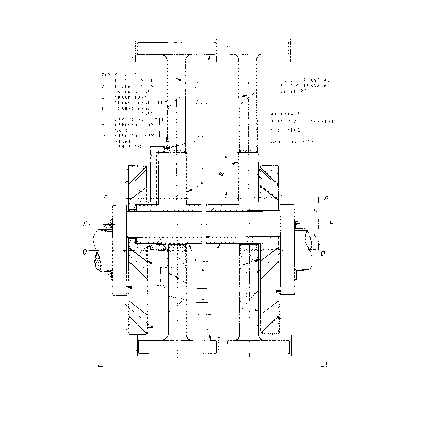
Also please see page 6, Picture #1.
Picture #2, page 7 here, shows more general case of my design.

2,195,886 -4- 25.08.1999.
Wojciech Barski
E 2195888
- I have found that these drawbacks may be overcome by placing
a cam sleeve (7) on the crank of a crankshaft (4), with a running
fit. The cam sleeve carries at least one circular cam (8) for
a double-sided piston (2) and (13). The piston may be also single,
as (2) or (13). The circular cams are offset from the crank axis
by the amount equal a crankthrow (see picture #1, lines 00, BB, AA,
dimension r). Line AA passes through the centre of circular cam (8).
The circular cam (8) is partially placed into a circular cam ring
(10), with a running fit. The cam ring (10) terminates on the left
side having a conical planet gear (5). The cam ring (10) may
move on the left cylindrical end of the cam sleeve, as well as
on the crank.
The cam sleeve at its right end terminates in another conical
planet gear (6).
The double sided piston (2) and (13) is fitted on the circular
cam (8) with proper play. The pistons (2) and (13) sit in two
opposite in line cylinders. The axis of the cylinders intersects
with the main bearing axis 00 of the crankshaft. The double piston
may be reduced to one.
Another circular cam (9) with its own pistons may be added. The
axis of the cylinders has to cut the 00 axis, but the new cylin-
ders need not to be in the same plane as the former set of cylin-
ders, enabling different configurations of cylinders ( X, cross,
U, etc.).
The left conical planet gear (5) meshes with an internal conical
gear (3) on the left.
The right conical planet gear (6) meshes with the right internal
conical gear (3).
The gear ratio is 1:2. Planet gear has one half of the teeth of
the internal gear.
The conical internal gears (3) are installed firmly in the housing.
The oil is supplied also between the cam ring (10) and the cam
sleeve (7), and circular cam (8), causing the axial expansion
of the planet gears (5) and (6). The oil may flow in via one-
directional valve to resist compression of cam ring (10) against
cam sleeve(7). In this way there is automatic compensation-
elimination of backlash, crucial in rectilinear movement of the
circular cam (8), so no side forces are transmitted from piston
to the cylinder wall.
The length of teeth contact in conical gears is substantially
bigger than for cylindrical gears, so the contact stresses are
smaller. The design employs conical gears, which are more of
a general class of gears than cylindrical ones. In this sense
my design is a generalization of Pitts design, see picture #2.
Conical gears offer far smaller sensitivity to radial plays of
the main and crank bearings, or movements caused by gas, inertia
or vibrations, so the life of mechanism will be longer.
Gears may be of different sizes, provided the gear ratio is 1:2.
As it has been pointed out here, the design combines the best
features enabling the practical application of my design to a
modern piston engine with internal'combustion, built for speed.
The sinusoidal piston movement in relation to crank rotation
eliminates the higher harmonics completely, releasing extra
strength of material for higher revolutions of the crankshaft.
For the same materials used, this design is able to withstand
way higher speeds than a typical crankshaft system.

Representative Drawing
A single figure which represents the drawing illustrating the invention.
Administrative Status

2024-08-01:As part of the Next Generation Patents (NGP) transition, the Canadian Patents Database (CPD) now contains a more detailed Event History, which replicates the Event Log of our new back-office solution.

Please note that "Inactive:" events refers to events no longer in use in our new back-office solution.

For a clearer understanding of the status of the application/patent presented on this page, the site Disclaimer , as well as the definitions for Patent , Event History , Maintenance Fee  and Payment History  should be consulted.

Event History

Description Date
Inactive: Expired (new Act pat) 2017-01-24
Maintenance Request Received 2015-11-19
Maintenance Request Received 2014-11-27
Maintenance Request Received 2013-12-19
Maintenance Request Received 2012-12-07
Grant by Issuance 2000-04-11
Inactive: Cover page published 2000-04-10
Pre-grant 2000-01-19
Inactive: Final fee received 2000-01-19
Notice of Allowance is Issued 2000-01-14
Letter Sent 2000-01-14
Inactive: Application prosecuted on TS as of Log entry date 2000-01-10
Inactive: Status info is complete as of Log entry date 2000-01-10
Inactive: Approved for allowance (AFA) 1999-12-21
Inactive: Advanced examination (SO) fee processed 1999-03-25
Letter sent 1999-03-25
Advanced Examination Determined Compliant - paragraph 84(1)(a) of the Patent Rules 1999-03-25
Application Published (Open to Public Inspection) 1998-07-24
Small Entity Declaration Determined Compliant 1997-01-24
Request for Examination Requirements Determined Compliant 1997-01-24
All Requirements for Examination Determined Compliant 1997-01-24

Abandonment History

There is no abandonment history.

Maintenance Fee

The last payment was received on 1999-11-08

Note : If the full payment has not been received on or before the date indicated, a further fee may be required which may be one of the following

  • the reinstatement fee;
  • the late payment fee; or
  • additional fee to reverse deemed expiry.

Patent fees are adjusted on the 1st of January every year. The amounts above are the current amounts if received by December 31 of the current year.
Please refer to the CIPO Patent Fees web page to see all current fee amounts.

Fee History

Fee Type Anniversary Year Due Date Paid Date
MF (application, 2nd anniv.) - small 02 1999-01-25 1998-11-13
Advanced Examination 1999-03-25
MF (application, 3rd anniv.) - small 03 2000-01-24 1999-11-08
Final fee - small 2000-01-19
MF (patent, 4th anniv.) - small 2001-01-24 2000-11-24
MF (patent, 5th anniv.) - small 2002-01-24 2001-11-19
MF (patent, 6th anniv.) - small 2003-01-24 2002-12-06
MF (patent, 7th anniv.) - small 2004-01-26 2003-11-17
MF (patent, 8th anniv.) - small 2005-01-24 2004-12-02
MF (patent, 9th anniv.) - small 2006-01-24 2005-11-18
MF (patent, 10th anniv.) - small 2007-01-24 2006-11-15
MF (patent, 11th anniv.) - small 2008-01-24 2007-11-14
MF (patent, 12th anniv.) - small 2009-01-26 2008-11-06
MF (patent, 13th anniv.) - small 2010-01-25 2009-11-06
MF (patent, 14th anniv.) - small 2011-01-24 2010-12-06
MF (patent, 15th anniv.) - small 2012-01-24 2011-11-28
MF (patent, 16th anniv.) - small 2013-01-24 2012-12-07
MF (patent, 17th anniv.) - small 2014-01-24 2013-12-19
MF (patent, 18th anniv.) - small 2015-01-26 2014-11-27
MF (patent, 19th anniv.) - small 2016-01-25 2015-11-19
Owners on Record

Note: Records showing the ownership history in alphabetical order.

Current Owners on Record
WOJCIECH GRZEGORZ BARSKI
Past Owners on Record
None
Past Owners that do not appear in the "Owners on Record" listing will appear in other documentation within the application.
Documents

To view selected files, please enter reCAPTCHA code :


To view images, click a link in the Document Description column. To download the documents, select one or more checkboxes in the first column and then click the "Download Selected in PDF format (Zip Archive)" or the "Download Selected as Single PDF" button.

List of published and non-published patent-specific documents on the CPD .

If you have any difficulty accessing content, you can call the Client Service Centre at 1-866-997-1936 or send them an e-mail at CIPO Client Service Centre.


Document
Description 
Date
(yyyy-mm-dd) 
Number of pages   Size of Image (KB) 
Claims 1997-05-08 1 20
Description 1997-05-08 1 13
Abstract 1997-05-08 2 62
Drawings 1997-05-08 1 31
Abstract 1999-12-21 2 75
Description 1999-12-21 2 116
Claims 1999-12-21 1 59
Drawings 1999-12-21 3 105
Representative drawing 1998-07-21 1 12
Representative drawing 2000-03-07 1 23
Notice: Maintenance Fee Reminder 1998-10-26 1 118
Notice: Maintenance Fee Reminder 1999-10-25 1 119
Commissioner's Notice - Application Found Allowable 2000-01-13 1 166
Notice: Maintenance Fee Reminder 2000-10-24 1 119
Notice: Maintenance Fee Reminder 2001-10-24 1 121
Notice: Maintenance Fee Reminder 2002-10-27 1 118
Notice: Maintenance Fee Reminder 2003-10-26 1 114
Notice: Maintenance Fee Reminder 2004-10-25 1 119
Notice: Maintenance Fee Reminder 2005-10-24 1 118
Notice: Maintenance Fee Reminder 2006-10-24 1 118
Notice: Maintenance Fee Reminder 2007-10-24 1 122
Notice: Maintenance Fee Reminder 2008-10-26 1 130
Notice: Maintenance Fee Reminder 2009-10-26 1 120
Notice: Maintenance Fee Reminder 2010-10-25 1 129
Notice: Maintenance Fee Reminder 2011-10-24 1 121
Notice: Maintenance Fee Reminder 2012-10-24 1 120
Notice: Maintenance Fee Reminder 2013-10-27 1 128
Notice: Maintenance Fee Reminder 2014-10-26 1 120
Notice: Maintenance Fee Reminder 2015-10-26 1 120
Fees 2002-12-05 1 75
Fees 2003-11-16 1 65
Correspondence 2000-01-18 2 115
Fees 2000-11-23 1 82
Fees 2001-11-18 1 71
Fees 1998-11-12 2 145
Fees 1999-11-07 2 97
Fees 2004-12-01 1 63
Fees 2005-11-17 1 63
Fees 2006-11-14 1 103
Fees 2007-11-13 1 81
Fees 2008-11-05 1 61
Fees 2009-11-05 3 263
Fees 2010-12-05 1 58
Fees 2011-11-27 1 77
Fees 2012-12-06 1 70
Fees 2013-12-18 1 185
Fees 2014-11-26 1 68
Maintenance fee payment 2015-11-18 1 72
Prosecution correspondence 1997-01-23 20 737
Courtesy - Office Letter 1998-11-25 1 21
Correspondence related to formalities 1998-11-25 1 25
Courtesy - Office Letter 1997-02-17 1 13
Prosecution correspondence 1999-03-24 1 60
Examiner Requisition 1998-08-17 2 45
Examiner Requisition 1998-08-17 2 54
Prosecution correspondence 1998-10-06 9 259
Examiner Requisition 1998-12-06 3 87
Prosecution correspondence 1998-12-13 7 179
Examiner Requisition 1999-03-21 5 153
Prosecution correspondence 1999-04-06 4 137
Examiner Requisition 1999-05-16 4 168
Prosecution correspondence 1999-08-29 1 30
Prosecution correspondence 1999-09-07 1 23
Examiner Requisition 1999-09-19 1 40
Prosecution correspondence 1999-10-13 1 39
Examiner Requisition 1999-10-31 2 67
Prosecution correspondence 1999-11-16 1 24
Prosecution correspondence 1999-11-24 1 34