Une partie des informations de ce site Web a été fournie par des sources externes. Le gouvernement du Canada n'assume aucune responsabilité concernant la précision, l'actualité ou la fiabilité des informations fournies par les sources externes. Les utilisateurs qui désirent employer cette information devraient consulter directement la source des informations. Le contenu fourni par les sources externes n'est pas assujetti aux exigences sur les langues officielles, la protection des renseignements personnels et l'accessibilité.
L'apparition de différences dans le texte et l'image des Revendications et de l'Abrégé dépend du moment auquel le document est publié. Les textes des Revendications et de l'Abrégé sont affichés :
| (12) Brevet: | (11) CA 2195886 |
|---|---|
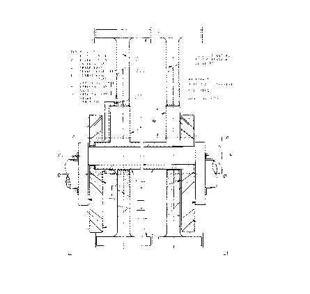
| (54) Titre français: | VILEBREQUIN A PISTONS A TETES OPPOSEES POUR MOTEUR A CYLINDRES MULTIPLES |
| (54) Titre anglais: | MULTICYLINDER BOXER CRANKSHAFT ASSEMBLY |
| Statut: | Durée expirée - au-delà du délai suivant l'octroi |
| (51) Classification internationale des brevets (CIB): |
|
|---|---|
| (72) Inventeurs : |
|
| (73) Titulaires : |
|
| (71) Demandeurs : |
|
| (74) Agent: | |
| (74) Co-agent: | |
| (45) Délivré: | 2000-04-11 |
| (22) Date de dépôt: | 1997-01-24 |
| (41) Mise à la disponibilité du public: | 1998-07-24 |
| Requête d'examen: | 1997-01-24 |
| Licence disponible: | S.O. |
| Cédé au domaine public: | S.O. |
| (25) Langue des documents déposés: | Anglais |
| Traité de coopération en matière de brevets (PCT): | Non |
|---|
| (30) Données de priorité de la demande: | S.O. |
|---|
Dans la plupart des moteurs à combustion interne et des compresseurs ordinaires, se trouvent un piston, se déplaçant dans un cylindre, une bielle et un vilebrequin, agissant en tant que système de vilebrequin. Les forces d'inertie et les forces dues aux gaz pressent le piston contre la paroi latérale du cylindre et produisent des contraintes de flexion dans la bielle. Avec l'augmentation de la vitesse, l'effet des forces d'inertie peut dépasser celui des forces dues aux gaz. La deuxième force d'inertie harmonique peut provoquer des contraintes plus grandes que celles de sa première harmonique. Cela sollicite fortement tous les composants, ce qui oblige à limiter la vitesse et la puissance. L'équilibrage est également difficile.
In typical internal combustion engines and compressors, etc., it is known to have a piston, moving in a cylinder, connecting rod and a crankshaft, as a crankshaft system. The gas and inertia forces press the piston against the cylinder side wall and produce bending stresses in the connecting rod. With increased speed the effect of inertia forces may exceed this of gas forces. The second harmonic inertia force may cause bigger stresses than its first harmonic. This puts heavy demand on all components, posing limitations to speed and power. Balancing is also difficult.
Note : Les revendications sont présentées dans la langue officielle dans laquelle elles ont été soumises.
Note : Les descriptions sont présentées dans la langue officielle dans laquelle elles ont été soumises.
2024-08-01 : Dans le cadre de la transition vers les Brevets de nouvelle génération (BNG), la base de données sur les brevets canadiens (BDBC) contient désormais un Historique d'événement plus détaillé, qui reproduit le Journal des événements de notre nouvelle solution interne.
Veuillez noter que les événements débutant par « Inactive : » se réfèrent à des événements qui ne sont plus utilisés dans notre nouvelle solution interne.
Pour une meilleure compréhension de l'état de la demande ou brevet qui figure sur cette page, la rubrique Mise en garde , et les descriptions de Brevet , Historique d'événement , Taxes périodiques et Historique des paiements devraient être consultées.
| Description | Date |
|---|---|
| Inactive : Périmé (brevet - nouvelle loi) | 2017-01-24 |
| Requête visant le maintien en état reçue | 2015-11-19 |
| Requête visant le maintien en état reçue | 2014-11-27 |
| Requête visant le maintien en état reçue | 2013-12-19 |
| Requête visant le maintien en état reçue | 2012-12-07 |
| Accordé par délivrance | 2000-04-11 |
| Inactive : Page couverture publiée | 2000-04-10 |
| Préoctroi | 2000-01-19 |
| Inactive : Taxe finale reçue | 2000-01-19 |
| Un avis d'acceptation est envoyé | 2000-01-14 |
| Un avis d'acceptation est envoyé | 2000-01-14 |
| Lettre envoyée | 2000-01-14 |
| Inactive : Dem. traitée sur TS dès date d'ent. journal | 2000-01-10 |
| Inactive : Renseign. sur l'état - Complets dès date d'ent. journ. | 2000-01-10 |
| Inactive : Approuvée aux fins d'acceptation (AFA) | 1999-12-21 |
| Inactive : Taxe de devanc. d'examen (OS) traitée | 1999-03-25 |
| Lettre envoyée | 1999-03-25 |
| Avancement de l'examen jugé conforme - alinéa 84(1)a) des Règles sur les brevets | 1999-03-25 |
| Demande publiée (accessible au public) | 1998-07-24 |
| Déclaration du statut de petite entité jugée conforme | 1997-01-24 |
| Exigences pour une requête d'examen - jugée conforme | 1997-01-24 |
| Toutes les exigences pour l'examen - jugée conforme | 1997-01-24 |
Il n'y a pas d'historique d'abandonnement
Le dernier paiement a été reçu le 1999-11-08
Avis : Si le paiement en totalité n'a pas été reçu au plus tard à la date indiquée, une taxe supplémentaire peut être imposée, soit une des taxes suivantes :
Les taxes sur les brevets sont ajustées au 1er janvier de chaque année. Les montants ci-dessus sont les montants actuels s'ils sont reçus au plus tard le 31 décembre de l'année en cours.
Veuillez vous référer à la page web des
taxes sur les brevets
de l'OPIC pour voir tous les montants actuels des taxes.
Les titulaires actuels et antérieures au dossier sont affichés en ordre alphabétique.
| Titulaires actuels au dossier |
|---|
| WOJCIECH GRZEGORZ BARSKI |
| Titulaires antérieures au dossier |
|---|
| S.O. |

