Note: Descriptions are shown in the official language in which they were submitted.
2196099
W096103228 PCTIUS94108661
1
PRODUCE WASHER
Background of the Invention
1. Field of the Invention
The present invention relates to washing apparatus
and, more particularly, to apparatus for washing produce.
2. Description of Related Art
Washing machines for crockery have been available
for years. Such machines provide racks for supporting
the crockery on edge or inverted to encourage drip drying
after the washing process. The cleaning function is
performed in part by a plurality of nozzles, whether
stationary or moveable, which a spray pattern of fine
water droplets in the form of a hollow expanding cone
with a relatively high impact force. The washing
function is substantially aided by the use of very hot
water and the chemical deterging and degreasing
properties of a cleaning agent.
For produce, including fruits and vegetables, a
spray providing fine water droplets having a substantial
impact force would bruise or damage the produce and such
sprays must be precluded. The use of a cleansing agent
to wash produce would leave an unacceptable after taste
unless extraordinary and time consuming rinsing were
incorporated. Moreover, the cleaning agent may produce
an unacceptable chemical reaction with the produce that -
would result in deterioration or damage of the produce.
Finally, a high temperature washing fluid would wilt or
otherwise damage the produce.
219 ~ ~ ~ ~ PCT/US9410S661
WO 96f03228
a
The produce washers known provide a swirling
immersion bath that provides a gentle rinse to the
produce to prevent damage and deterioration.
Unfortunately, such gentle rinsing fails to clean the
crevices, interstices and other surface perturbations of
the produce. Moreover, debris lodged within folds, in
depressions or in cavities is usually not removed. Thus,
such produce washers are primarily used for an initial
washing operation to be followed by hand washing prior to
presenting the produce for cooking or eating. Manually
operated produce washers are also known and are effective
to the extent an operator diligently directs the washing
fluid on and about the produce.
summary of the invention ....... .. _ . ..", . . ",
Produce is loaded upon a basket of mesh material
placed within a closeable cabinet. A plurality of
nozzles, which nozzles may be fixed or movable, are
located above and below and possibly on the sides of the
basket to direct sprays of washing fluid onto the
produce; preferably, the washing fluid is slightly
acidic. The nozzles are configured to provide a non
hollow expanding cone spray pattern to provide relatively
large but slow moving droplets to gently agitate and to
scour the produce surfaces impinged. The large droplets
tend to dislodge, float and convey any liquid or solid
debris on the produce. Because of the relatively low
impact forces of the droplets, soft surface produce, such
as strawberries-, may be washed equally as well as hard
surfaced produce, such as celery. The washing fluid
containing debris is filtered and collected in a trough.
A pump recycles the washing fluid from the trough through
the nozzles for a period of time sufficient to complete
the washing process. After washing is complete, the
CA 02196099 2000-11-21
3
washing fluid is discharged. A rinsing fluid, such as tap
water, is sprayed onto the produce to rinse the produce and
remove any residual washing fluid or debris.
The present invention provides a washer for: washing
produce of any type; a produce washer for washing robust and
tender produce with equal effectiveness and without damage;
a produce washer for simultaneously washing a mixture of
different produce; a produce washer for recycling the
washing fluid; a produces washer having a plurality of
nozzles for emitting an expanding non hollow cone of
droplets of washing fluid; and a produce washer for washing
produce of various kinder during a washing cycle and for
rinsing the washed produce during a rinse cycle.
The present invention also provides: a plurality of
nozzles for omnidirectionally spraying produce with a
washing fluid; and stationary and moveable nozzles for
spraying produce with a washing fluid.
Further the present invention provides a method for
washing produce.
These and other asps:cts of the present invention will
become apparent to those, skilled in the art as the
description of the prese=nt invention proceeds.
R'O 96103228 ~ ~ ~ 6 0 9 9 p~~S94108661
4
Rr;ef Descrix~tion of the Drawincs _"",
The present invention will be described with greater
specificity and clarity with reference to the following '
drawings, in which:
Figure 1 illustrates a cabinet housing a produce
washer;
Figure 2 is a cross sectional side view of the
produce washerillustrated in Figure 1;
Figure 2a is a cross sectional view taken along
lines 2a-2a illustrated in Figure 2;
Figure 3 is a partial cross sectional front view of
the produce washer illustrated in Figure 1;
Figure 4 is a partial cross sectional rear view of
the produce washer illustrated in Figure 1;
Figure 5 is a representative illustration of the
plumbing for the washing fluid of the produce washer;
Figure 6 is a partial top view of the plumbing
interconnecting certain nozzles;
Figure 7 is a partial side view illustrating the
plumbing for top and bottom nozzles;
Figure 8 is a partial view of the plumbing for a
plurality of top, bottom and side mounted nozzles;
Figure 9 is a partial cross sectional view
illustrating the spray patterns of the nozzles depicted
in Figure 8;
Figure 10:.:is a partial cross sectional side view of
the nozzles illustrated in Figure 9;
Figure 11 is a cross sectional view of a
conventional hollow expanding cone spray pattern of a
conventional nozzle; and
Figure 12 illustrates the spray pattern of the
nozzles used in the produce washer; and
Figure 13is a cross sectional view taken along
lines 13-13, as shown in Figure 12 and illustrating the
2196099
W096103228 PCT/U594108661
spray pattern of-the nozzles used with the produce
washer.
D~scrintion of the Preferred Embodiment
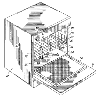
A produce washer 10 housed within a cabinet 12 is
illustrated in Figure 1.- The cabinet includes a
closeable door 14 for providing access to the interior of
the cabinet to load and unload the produce to be washed.
A basket 16, formed of a mesh or other easily water
permeable material supports and contains the produce to
be washed. The basket is mounted upon opposed ledges 18,
20, which ledges may include rollers 22 or similar
devices to assist in sliding the basket into and out of
cabinet 10. A shelf 24 extends across the lower end of
compartment 26 defined by cabinet 10; the shelf may
include one or more substantially sized holes or
apertures 28 to accommodate drainage of washing fluid. A
filter 30 is removably lodged or mounted beneath shelf 24
to filter debris from the washing fluid flowing through
aperture 28. Preferably, a cutout switch (not shown),
such as a magnetic switch, is enabled upon mounting of
the filter to prevent operation of the produce washer
unless the filter is in place. A control panel 32 is
mounted on the exterior of cabinet 10 to provide start,
stop and other controls for operation of produce washer
10. Moreover, it may include timers to vary the time of
fluid flow, pressure controls in combination with
pressure gauges to vary the pressure of the fluid flow,
and flow controls to vary the quantity of fluid recycled.
Referring jointly to Figures 2, 3 and 4, further
details of produce washer 10 will be described. Cabinet
' 12 includes side walls 40, 42, rear wall 44, top 46 and
bottom 48. Compartment 26 is defined by false side walls
50, 52, false rear wall 54, false top 56 and false bottom
WO 96/03228 219 6 0 9 ~ PCTIUS94108661
6
58. The spaces intermediate compartment 26 and cabinet
12 are used for routing plumbing and electrical conduits,
as illustrated in part in Figures 2, 3 and 4.
Filter 30 is supported upon shoulders 60, 62
extending inwardly from false side walls 50, 52. A
further shoulder 64 for supporting the rear edge of the
filter may extend from false rear side wall 54. Upon
closing of door 14, the door engages seals 70, 72, 74 and
76 extending about opening 78 to compartment 26.
Thereby, upon closing the door; compartment 26 will
become essentially watertight. False bottom 58 serves in
the manner of a trough 80 to collect the washing fluid.
It includes a downwardly extending cone shaped drain 82
for discharging the water. An electrically actuated pump
84 includes a conduit 86 extending from inlet 88 in fluid
communication with drain 82 to draw water from trough 80.
Outflow from pump 84 is conveyed via conduit 9o to a
conduit tree 92 for discharging water through a plurality
of outlets or nozzles into compartment 26. Conduit 94 of
the conduit tree. extends beneath shelf 24 and upwardly
through aperture 28. An arm 95, including nozzles 96, 98
is rotatably mounted at the end of conduit 92 to locate
the arm within compartment 26 and beneath basket 18.
Mounting 100 accommodates rotatable movement of arm 95
and also accommodates flow of washing fluid from within
conduit 92 into the arm for expulsion through nozzles 96,
98. The spray pattern of the nozzles is directed
upwardly into basket 18. Conduit 110 of conduit tree 92
conveys washing fluid through an aperture in false top
56. An arm 112; supporting nozzles 114, 116 is rotatably
mounted by mounting 118 at the terminal end of conduit
110. The mounting accommodates rotation of the arm and
accommodates flow of washing fluid from conduit 110 into
the arm for expulsion through nozzles 114, 116. The
washing fluid sprayed from the nozzles is directed
WO96103228 219 6 ~ 9 9 P~~s94/08661
7
downwardly into basket 18. Nozzles 96, 98 are mounted
upon arm 95 at an angle of the vertical axis to provide
a reaction force upon expulsion of the washing fluid to
' induce rotation of the arm, as depicted by arrow 102.
Similarly, nozzles 114, 116 are mounted at an angle off
the vertical axis to provide a reaction force upon
expulsion of washing fluid to induce rotation of the
arm, as depicted by arrow 120. The canting of the
nozzles is represented by canted nozzle 114 attached to
arm 112 as depicted in Figure 2a. As particularly
depicted in Figures 3 and 4, a plurality of nozzles 96
and 98 may be mounted upon arm 95. Similarly, a
plurality of nozzles 114, 116 may be mounted upon arm
112. it is understood that a seal 122 may be disposed
between conduit 110 and false top 56 to preclude water
flow therebetween. Similarly, a seal 104 may be
2o disposed about conduit 92 in false rear wall 54 to
prevent water flow therebetween.
.
As particularly illustrated in Figures
3, 4 and 5,
conduit tree 92 may include a drain conduit 130 and
valve 132 controlling outflow through the drain
conduit. Thereby, pump 84 may also be used to drain
trough 80 on completion of a washing cycle.. Water
inlets 132, 134 are in fluid communication with trough
80 to accommodate inflow of washing fluid. One of
these inlets may be connected to a source of water at
3o ambient temperature and the second inlet may be
connected to a source of chilled water at a
predetermined temperature. Alternatively, one of the
inlets may be used to introduce an additive, such as a
. weak acidic solution which is beneficial for cleaning
various types of produce.
SJBSTITU1'E SHEET
z~g~a~9
WO96103228 PCTIUS94/08661
7/1
Referring to Figures 6 and 7, there is illustrated
an alternate embodiment of conduit tree 92 which
conduit tree 140 provides a plurality of fixed nozzles '
for spraying a washing fluid upon the produce to be
washed. The conduit tree includes arms 142, 144
t..r..,.,~+a.,.. ,.,
i5
ao
30
SUBSTIME SHEET
W096103228 21 ~ 6 0 ~ q PCTlU894108661
8
nozzles 146, 148, respectively. A further nozzle 150 is
disposed at the junction of the arms and a nozzle 152 is
disposed at the bend of arm 144. Each of these nozzles
' extends through false top 56 in sealing engagement
therewith to prevent water flow upwardly therebetween.
' Nozzles 146, 148, 150 and 152 direct washing fluid
downwardly into basket 18 within compartment 26.
Similarly configured arms 154, 156 are disposed beneath
shelf 24 and support four nozzles in the manner of arms
142, 144 and of which nozzles 158, 160 are illustrated.
The four nozzles extending through shelf 24 emit an
upwardly directed spray of washing fluid into basket 18.
A complex conduit tree 170 is illustrated in Figures
8, 9 and 10. A conduit tree of this type provides a
plurality of downwardly directed nozzles, upwardly
directed nozzles, inwardly directed nozzles from opposed
sides and nozzles located within compartment 26 to spray
water both upwardly and downwardly simultaneously. A
complex conduit tree of this type is particularly useful
wheri a pair of spaced apart baskets (242, 244) are
located in the compartment within the cabinet. Conduit
tree 170 includes a manifold 172 connected to the outlet
of pump 174, which pump draws washing fluid from a trough
at the bottom-of the cabinet through inlet conduit 176.
An upright conduit 178 extends from manifold conduit 172
and supports laterally located arm conduits 180, 182.
Arm conduit 18o supports one or more laterally directed
nozzles 184. Similarly, arm conduit 182 supports one or
more laterally directed nozzles 186. An arm conduit 188
extends from upright conduit 178 and supports one or more
upwardly directed nozzles 190. Another arm conduit 192
extends from upright conduit 178 and supports one or more
" downwardly directed nozzles 194 and one or more upwardly
directed nozzles 196. A further arm conduit 198 extends
from upright conduit 178 and supports one or more
2196099
WO 96103228 PCTIUS94108661
9
downwardly directed nozzles 200. Nozzles 202 may be
mounted upon upright conduit 178 to direct washing fluid
laterally. An upright conduit 204 extending from
manifold conduit 172, supports lateral arm conduits 206, '
208. one or more nozzles 21o may be mounted upon lateral
arm conduit 206 to direct washing fluid laterally. '
Similarly, one or more nozzles 212 are supported by
lateral arm conduit 208 to direct washing fluid
laterally. Arm conduit 214 extends from upright conduit
204 and supports one or more nozzles 216 to direct
washing fluid upwardly. Arm conduit 218 extends from
upright conduit 204 and supports one or more nozzles 220
to direct washing fluid downwardly and one or more
nozzles 222 to-direct washing fluid upwardly. Arm
conduit 224 also extends from upright conduit 204 and
includes one or more nozzles 226 to direct washing fluid
downwardly. One or more nozzles 228 may be disposed
along upright conduit 204 to direct washing fluid
laterally.
Figures 9 and 10 illustrate a cabinet 240 for
housing a conduit tree, such as conduit tree 170
illustrated.in Figure 8, and a pair of-baskets 242, 244.
Basket 242 may be supported upon ledges 245, 246 and rear
ledge 247 and basket 244 may be supported upon leges
248,249 and rear ledge 250. A door 252 provides access
to interior compartment 254 defined by false side walls,
top and bottom, as described above with reference to
cabinet 12. A shelf 256 includes a central aperture 258
to accommodate-drainage of the washing fluid. Additional
apertures, of which apertures 260, 262 and 264 are shown,
may encircle nozzles 190, 216 extending upwardly from
arms 188, 214, respectively. Washing fluid flowing
through the apertures in shelf 25b- is filtered by filter
270. A trough 272 is disposed beneath the filter to
catch and collect drained washing fluid. A cone 274
WO 96103228 219 6 0 9 9 PCTIUS94108661
provides for discharge of the washing fluid from trough
272 into inlet conduit 176 and to pump 174. As
illustrated in Figures 9 and 10, the conduits forming
' conduit tree 170 may be disposed in the spaces between
the false walls defining compartment 254 and the exterior
walls of cabinet 240. Preferably, seals are provided
about each of the nozzles penetrating the walls of
compartment 254 to preclude inadvertent water flow
therebetween.
As particularly noted in Figures 8 and 9, nozzles
200 provide a cone of spray 280 downwardly upon and into
242. A similar cone of spray 282 is provided by nozzles
226. A cone of spray 284 is provided by nozzles 186
laterally upon and into basket 242. Nozzles 184 provide
a cone of spray 286 laterally upon and into basket 244.
Nozzles 210 provide a cone of spray 288 laterally upon
and into basket 244. Nozzles 212 provide a cone of spray
290 laterally and upon basket 242. Nozzles 196 provide
an upwardly directed cone of spray 292 upon and into-the
bottom of basket 242. Nozzles 222 provide an upwardly
directed cone of spray 294 upon and into the bottom of
basket 242. Nozzles 194 provide a cone of spray 296 upon
and into the top of basket 244. Nozzles 220 provide a
cone of spray 298 upon and into the top of basket 244.
Upper ones of nozzles 202 provide a cone of spray
laterally and forwardly upon and into the rear of basket
242. Similarly, upper ones of nozzles 228 provide a
lateral cone of spray upon and into the rear ofbasket
242. Lower ones of nozzles 202 provide a lateral cone of
spray upon and into the rear of basket 244. Similarly,
the lower ones of nozzles 228 provide a cone of spray
laterally upon and into the rear of basket 244. Nozzles
190 provide a cone of spray 300 directed upwardly upon
and into the bottom of basket 244. Nozzles 216 provide a
PCT/US94108661
WO 96103228
11
cone of spray 302 directed upwardly upon and into the
bottom of basket 244.
Upon inspection, it will become evident that the
nozzles attendant conduit tree 170 spray both baskets
242, 244 from the top, bottom the opposed sides and the
rear. Such deluge of water will provide the requisite
agitation and scouring action to cleanse debris from the
produce supported by or located within the baskets. Any
dislodged debris flows with the washing fluid downwardly
by gravity through the apertures in shelf 256 onto filter
270. The filter filters the debris from the washing
fluid and the filtered washing fluid is collected within
trough 272. Pump 274 draws the filtered washing fluid
from the trough and forces expulsion of the filtered
washing fluid through the nozzles. Such washing action
will continue for a predetermined time, as set by the
controls located upon control panel 308.
Subsequent to draining of the washing fluid on
completion of a washing cycle, a quantity of fresh water
or rinse solution is introduced to the trough. The fresh
water or rinsesolution is pumped through the conduits
and nozzles onto the produce to wash away and rinse any
residual washing or cleaning solution from the produce.
Conventional nozzles of the type used for cleansing
items with water or liquid spray emit a cone shaped spray
pattern 330 which is hollow, as '111ustrated in Figure 11.
Any item intercepting the spray pattern will have
impinged thereupon an annular band 332 of water or
washing fluid.-- Generally, the droplets 333 forming the
spray are relatively small sized and travelling at a
relatively high rate. The resulting kinetic energy of
each droplet is relatively high. Because the area of the
droplet impinging upon the item to be washed is
relatively small, the force, in pounds per square inch,
imposed by the droplet is relatively high. For crockery
W096103228 ~ ~ ~ ~ ~ ~ ~ PCT/US94108661
12
and the like, the destructive effect of this force is
inconsequential. For soft tissue items, such as produce,
including strawberries, other berries, lettuce, etc.,
bruising and tissue damage will occur. To obtain a
relatively large mass of water or washing fluid impinging
' upon the item to be washed per unit of time requires a
relatively high velocity of the hollow cone shaped spray
pattern. The higher velocity or flow rate will
contribute to washing or flooding to help convey debris
and other foreign matter but the likelihood of damage to
delicate and soft tissue items being washed due to the
increased force of the spray pattern is exacerbated.
To avoid the actual and potential damage to soft
tissue items being washed, such as fruits and vegetables,
nozzles 334 of the type illustrated in Figure 12 have a
spray pattern 336 defining an expanding cone 338 and are
used with the produce washers described above. The spray
cone is not hollow as shown by spray pattern 330
illustrated in Figure 11 emanating from a conventional
nozzle. Instead, expanding cone 338 is filled with
randomly distributed droplets 340 emanating from nozzle
334. For a given flow rate from each of nozzles 334 and
the conventional nozzle producing hollow cone shaped
pattern 330, the axial flow rate per area of droplets 340
within the area defined by cone 338 is substantially less
than the flow rate per area of the droplets within the
area defined by annular band 332. This reduced flow rate
per area of nozzle 334 over that of conventional nozzles
will result in impingement upon the item being washed at
a lower force per unit area of the droplets since
droplets are disposed throughout the area of the cone
impinging upon the item being washed and not just within
' an annular band of the cone of water. Yet, the quantity
of washing fluid impinging upon the produce may be the
R'O 96103228 ~ ~ ~' ~ ~ ~ ~ PCT/US94f08661
13
same or more than that emanating from a conventional
nozzle.
Because individual droplets 340 impinge upon the
element being washed, repetitive impact forces will
impinge upon debris and other foreign matter present.
Such impacts will tend to agitate, scour and dislodge
debris and foreign matter from the element being washed.
As the impact forces are relatively low, damage to the
element being washed due to the impacts is relatively
unlikely. The substantial quantity of water or washing
fluid per unit area will tend to cause scouring flotation
and carrying away of dislodged debris and foreign matter.
Such agitation, scouring and flotation will be present in
crevices, depressions and even folds of the element being
washed and difficult to clean produce, such as lettuce
and broccoli can be readily cleaned. Because of the low
impact forces and low probability of damage, soft tissue
produce, such as strawberries and other fruits or
vegetables, are readily washed clean without ripping or
tearing of the outside skin.
For reasons not fully understood, it has been found
useful to add a weak acidic solution to the wash water
initially placed within the trough of the produce washer.
For example, the juice squeezed from half a lemon or a
small quantity of lemon abstract along with about a
tablespoon of common salt (N~C1) poured upon the screen
or into the trough prior to the washing cycle provides
somewhat better cleaning than plain tap water. This
suggested cleaning solution is equivalent to a mild
hydrochloric acid solution and is a very effective
cleaning solution. -Where readily available tap water may
be contaminated, it is suggested that purified water be
used as the washing fluid.
WO 96103228 ~ ~ ~ ~ ~ ~ ~ PCT/U594/08661
14
Produce, whether vegetables or fruits, vary
significantly in robustness. Moreover, the degree and
type of debris and contaminants present vary
' significantly. To accommodate such range of variations,
the control panel of the produce washer provides the
' capability of varying the water flow rates through the
nozzles to increase or decrease the impact forces of the
impinging droplets. Typically, the flow rate of the
recycling washing fluid is 7-9 gallons per minute and the
pressure at the nozzles is in the range of 100-110 psi.
Usually, only 1 to 1z gallons of washing fluid is-
consumed per washing cycle. These ranges of flow rate,
pressure and volume would also be applicable to the rinse
cycle. Further controls are provided to lengthen or
shorten the wash cycle and/or rinse cycle to perform the
washing and the rinsing operations as efficiently as
possible.
As representatively illustrated in Figures 2 and 4,
wires 350 and electrical conductors or cables 352 may be
routed through the space between the exterior walls of
the cabinet and the false walls of the compartment.
Similarly, as illustrated in Figures 5, 7 and 10,
conduits of plumbing trees 92, 140 and 170, may be routed
in the spaces between the exterior walls of the cabinet
and the false walls of the compartment. The pump and
associated valuing, when present, may be located in the
space between the bottom of the trough and the bottom of
the cabinet. The electrical conductors, the respective
locations of any electrical connectors, the plumbing
conduits and plumbing fixtures are shielded from the
water or washing fluid by the false walls of the
compartment in combination with the seals disposed about
the nozzles and related structure at the point of
penetration into the washing compartment.
W'O 96103228 2 ~ 9 6 0 9 9 PC1'/US94108661
While the principles of the invention have now been
made clear in an illustrative embodiment, there will be
immediately obvious to those skilled in the art many
modifications of structure, arrangement,- proportions,
elements, materials and components used in the practice
of the invention which are particularly adapted for
specific environments and operating requirements without
departing from those principles.