Note: Descriptions are shown in the official language in which they were submitted.
AN ADAPTIVE POWER CONTKOL AND CODING SCHEME
FOR ~IOBILE RADIO SYSTEMS
FiPI.I of
The present invention relates to the field of mobile radio comml~nir~tirrl.~ systems
and more particularly to the problem of reducillg the power consumed by wireless~lal~ lilL j while increasing the number of cimlllt~ -ollc supported.
~ a ~
Mobile radio channels are often vll~tv~ by t~le unpredictability of the channel
due to, inferalia~ rayleigh fading and long term shadow fading. The channel quality may
degrade as a result of several factors such as, for example, co-~hannel il.t~"rGIcl..v,
adjacent channel i...~,lrv~ e, IJlUL~ LiUIl path loss, and multi-path l~u~ iul~ (i.e.,
rayleigh fading). Tla~ llia~iù~l errors typically occur in bursts when fading causes the
signal level to go below the noise or i f~lCll~G level. Therefore, explicit measures often
15 need to bv taL.~en to maintain an acceptable level of quality of the lI~ allli~aiUIl over a radio
cl~annel.
Each radio channel connection typically has a reliability constraint associated with
it. This channel reliability may, for example, be defined in terms of the bit-error-rate
(BER) or, ' ~ , the word-error-rate (WER) as ~ - ;' '" c~l at the receiver. A given
2û connection will typically desire some particular average word-error-rate, W~,R,J~s. There
are two categories of techniques which have been heretofore employed for keeping the
WER from exceeding some ~/ICI~IIII;IIvd required threshold: (a) increasing the power
~r.~ncmitt~rl, and (b) improving the data encoding.
Various channel quality illl~lU~..Il.llL techniques have been heretofore proposed
25 and/or i~ Gd in each of these categories. For example, power control (ie.~ the
lldjustment of the ~ . ";~ power level) baced on the carrier-tû-ill.~. rvl. ,.~c ratio (ClR)
is one well-known technique for managing co-channel illt~lfclvll~G and incre;lsing
throughput in a multi-user Gllvilull~ lL. Power control may also be used for improving
the quality-of~service (QOS) over a cllanllel. Many portable radios and most base station
30 equipment have the ability to transmit at different power levels. The other technique which
2 2 ~ ;3 6 1 ~ 4
is frequently used for improv,ing the quality of the channel seen by the receiver is error
control by data encoding. Various encoding schemes have been heretofore proposedand/or il.l,JI..I ' d for present analog and digital cellular systems. Unfortunately, each
of these alternative approaches (i.e., power control and data encoding) has certain
5 respective drawbacks limiting their effectiveness.
The first approach -- power control -- has often been employed for reducillg co-cllannel interference and increasing the capacity of cellular radio systems. In a cellular
Lllvilull~ lL, for example~ the average received power at a receiver depends on the
. II ..,..:t.~ i.. of the channel and the distance between the transmitter and the receiver.
10 The loss in signal strength due to the distance factor is commonly referred to as the
"propagation path loss." In free space, the causes of Itlu~ Sa~iul~ path loss include the
frequency of 11 .,i~;. "I~f; and the distance between the transmitter and the receiver, d,
related as shown below:
Pr
P~ ~4rl~f/c)~ (1)
where, P, is tbe tranr,mitted power, Pr is the received power in free space. c is the speed of
15 light, and a is an attenuation constant.
As the mobile receiver moves away from the transmitter, the power of the received
signal decreases, the CIR also decreases, and, therefore, the WER experienced by the
receiver increases. Thus, as the distance between the transmitter and receiver increases,
power control schemes are used to increase the transmitted power so as to maintain the
20 signal power seen at the receiver and to keep the WER below a given threshold value.
There are, however, several disadvantages to ;.l~ rt ly increasing the
transmitted power. First, the battery power at a mobile unit is a limited resource and needs
to be conserved. Second, increasing the transmitted power on one channel, irrespective of
tl~e power levels used on other channels, can increase the co-channel interference seen on
25 other channels and thereby degrade the quality of ~la~la~ iull over these other cllannels.
Finally, there is a limit to which a transmitter can increa~se its power, and when that limit
~ 3 L~ I ~ {~ t
is reached, no further improiement in WER can be achieved with use of such a power
control technique.
The second appro~h -- data encoding -- also has its drawbacks. Specifically,
torward error corTection (FEC) and automatic repeat request (ARQ) are two well-known
S elTor control techniques commonly used for noisy channels. In a system that uses FF,C for
erTor control, for example. the transmitter encodes the data using a giYen code, while the
receiver, which has been informed of the code used. decodes the data at the receiYing end.
Many such systems using conventional block or convolutiollal codes have been e.Yplored
andlor employed.
Specitlcally, a code is said to be an (n,k,t) code if, for k illfo~ bits, the code
adds (n k) redundant bits so as to corTect any t errors in the resulting n bits. Power
transmitted per intormation bit for an (n,k,t) code may be defmed to be the value of (nlk)P,
where P is the power used in Ll, ~ one bit. The code rate of an (n,k,t) code may be
defined to be the value kln, i.e., the ratio of the number of information bits in a codeword
15 to the total number of bits. Given the channel conditions, the code rate must be chosen
careEully to satisfy the channel reli~bility It;yuil~ "lL~. If the BER c~ ,.L~d by the
channel is, for example, p~, and the channel is encoded using a bit-interleaved (n, k, ~) code,
then th~ WER for a word of size n bits as seen at the receiver is as follows:
~ER = ~ ) p~ Pb 1 ~ 2 ~
(Note that this equation assumes that ihe "bur.sty" nature of errors is countered by u6ing a
20 code which is v ~ ~y bit-interleaved, such that each bit erTor in a word is likely to be
in~ F.-nd.-nt of others.)
As the distance between the transmitter and the receiver increases, the signal
strength at the receiver decreases (assuming the power transmitted remains constant).
Hence, Ihe BER and the WER c~ ,cd at the receiver increase. Tn order to keep the25 WER within a ~.c~l ' threshold value, therefore, the encoding of the data needs to
be . u~lci~y~ d;..vly increased. If the encoding is increased, however, the tllroughput of the
4 2~ 9~1 ~4
wireless channel goes down, i.e., more redundant bits have to be transmitted for the same
number of i~lf(J-~--ali~l) bits. This can also increase the delay in ~ a given
amount of information. Hence, like power control, using only error correction to improve
ttle WER ~ .d by the recei~er also has serious drawbacks.
5 ~ of - T
In accordance with an illustrative clllbodi~ l of the present invention, a dynamic
combined power control and forward error correction control (FEC) technique for mobile
radio systems is used to decrease the power consumed by wireless l~al.~ while
increasing the number of ~ connections which may be supported thereby.
10 rvroreover, t'nis illustrative C~.,.I.~li.~l...t comprises a distributed technique, where individual
transmitter-receiver pairs adaptively determine the minimal power and FEC required to
satisfy specified quality-of-service (QOS) constraints.
Specifically, and in accordance with an illustrative ~,.,b~d,ii~ of the present
invention, a first portion of a signai is encoded with a first code to generate a first encoded
15 signal portion. Then, the first encoded signal portion is transmitted with a first power
level. Next, parameter data is received, wherein the parameter data is ~ ,O..~ iv~ of one
or more ~ ula~t.,liD~ of a received sigllal portion having been received by the receiver,
the received signal portion having been based on the transmiffed first encoded signal
portion. A second code and a second power level is then determined based on the received
20 parameter data, and a second portion of the signal is encoded with the second code to
generate a second encoded signal portion. Finaily, the second encoded signal portion is
transmitted with the second power level.
Brief ~ ~,' of' D'
Fig. I shows a typicai cell-based mobile wireless ~ ,llVil~ in
25 which an illustrative ~Il,I,o.l;.,...,l of the present invention may be advantageously
employed.
Fig. 2 shows one possible example of a table comprising a set of possible encoding
schemes for use in an illustrative ~ .Oli;ll~ of the present invention.
Fig. 3 shows a flow-chart illustrating a method of operation of a mobile radio
5 ~ 1 1 4
receiver operating in accordance with an illustrative ~ u~ . of the present invention.
Fig. 4 shows a flow-chart illustrating a method of operation of a mobile radio
transmitter operating in accordallce with an illustraLiYe embodiment of the present
illvention.
S ~ "
Fig. I shows a typical cell-based mobile wireless cu" ~ " ,c environment jn
which an illustrative rll,l.l~.l;.,.r,ll of the present invention may be advantageously
employed. The illustrative environment comprises a plurality of hexagonal cells 12, each
of which contains therein a ~ ,uulldillv base station 13 placed d~V ' Iy at the
10 center thereof, and one or nlore mobile units 14 (e.g., automobiles) located within various
ones of the cells. Each mobile unit 14 is in ~.VllllllUlli~ iUII with the base station
~,ull~ )olldillg to the cell in which the mobile unit is located, the ~u".",.",i. ~aiOn being
effectuated with use of wireless 1 ~ ions links IS. Some ~r all of these
l OIlllll 1;. ~;llll~ links may adva ll. vevusly comprise a two-way .-.:...".."";. ~lions link for
15 providing, e.g., two-way voice ~IJIIIIIIIIII;~ ' In addition, one or more interference
signals 16 may be present throughout the ~IV;lO~ Moreover, some or all of
~,..."",...,;.-:ions links 15 may themselves interfere with the ~ull~lu~ aLiOn being
effectuated by other ones of comml'r;~~ nc links 15.
A set of frequencies can be assigned to each cell such that each crmmlln~ tions
20 link 15 makes use of one of the frequencies assigned to the given cell. Cells using the
same set of rlc4u~n~i~s are ad~ u~,~vu~ly placed syllllll~tli~ally on the hexagonal grid.
A co-channel cell is defined as a cluster of seven hexagonal cells, and a given frequency
or channel is a~l~ v 'y assigned to only one cell in a co-channel cell.
Unlike prior art schemes that use only power control or only error-correction for
25 managing the quality of I, a ~ over a wireles.s channel, the illustrative ~ odilll~,.lt
of the present invention described herein makes judicious use of both power control und
error correction for improvement of channel quality. Moreover, a teedback loop is
advantageously used for changing the power as well as the encoding level, thereby
resulting ill a fully adaptive approach. The illu.strative method also comprises a distributed
30 approach that advall~..v,~,u ,l~ does not rely on a central decision making process, and,
6 7 I s3~
therefore, does not require ~ knowledge of the state of a plurality of
~u~ iOIls.
For purposes of ~Yrlsln~ri~n~ the tollowing ~ may be made regarding the
transmitter and receiver of the illustrative ~I-,I,odi~ ..l described herein:
1. All II~D~ S ha~e minimum and m~imum power levels at which they
can transmit signals.
2. The set of possible encoding schemes is given by a ~";d.,t~,l..li..~d set. C
= ~c"c2, . . . ~c ~, such aD, for example, the illustrative set of BCH (Bose,
Chaudhuri and 11"~ ,h. .") codes as shown in the table of Fig. 2.
3. The illustrative receiver monitors the observed power, P,b~, and the
word-error-rate, WER"bs. It call also observe the noise and i.lt..r~ ,c level, I"~s,
by monitoring the channel during periods when it is idle.
As described above, channel quality control using only power control may otten
be undesirable since it increases the power transmitted per i~-ru--lldliul~ bit. Similarly,
15 channel quality control using only FEC may not be beneficial to the system, since the
channel may have very low throughput if the data is too strongly encoded. Therefore, in
accordance with an illustrative rllll,~ of the present invention, a method wi~ich
incorporates both of these techniques is advantageously employed.
Specifically, a "power-code pair" is defined to l,ll~lld~ c the llall~ iUII
20 ~lld d~ls;li~Li~ provided on a given channel ~t a given time. A channel may be said to use
a given power-code pair, (P" c,), if it is ~ i..g at a power level P and the data being
sent on the channel is being encoded using code c,. In addition, a IJl~d~L~.,~lillt:d
"Code-WER" table is advantageously provided to the system, wherein each entry in the
table provides the vaiue of the CIR which is required for a given value of the WER and a
25 given encoding scheme. Specifically, an entry (c"~,) in the Code-WER table,
ull~.ulldillg to code Cj, and desired word-error-rate ~y, gives the CIR required at the
receiver for the receiver to experience a word-error-rate of w, when the data is encoded
7 2~ T ~
.
using code ci. (Note that all of the codes described herein are illustratively presurned to
be bit-interlea~ed cyclic cod~s, familiar to those of ordinary skill in the art.) The
word-error-rate for a data packet with k i"r~ ..lio,~ bits encoded using an (~I,k,t) code is
given by equation (2) above.
S In accordance with an illustrative ~ o til~ of the present invention. an entry
in the Code-WER table may be calculated as follows. Given the desired WER and the
code, the BER (p~) in equation (2) above can be adv.",lu6~,~,u~1y pr~ 1 BER is afunction of the CIR and the modulation scheme. ~lowing the modulation scheme, the
average CIR can be calculated from the BER. Assuming, for e~ample, the use of a binary
phase shift key (BPSK) modulation scheme and fast fades, the relationship between BER
and CIR is given by:
<~E~> =
2 1 1 1
C~R
From the above equations. a Code-WER table can be constructed for a given set of codes
and a uvl~ ul~ tillg set of desired word-error-rates.
In accordance with an illustrative embodiment of the present invention, each
tS transmitter-receiver pair individually determines the appropriate power-code pair to use
for its subsequent tl a~ 111 Specifically, based on parameter data received from the
receiver, the transmitter chooses a power-code pair, and then ~I~llllllUlli. ' the chosen
encoding scheme to the receiver. More particularly, the method of the illustrative
embodiment described herei~ operates as follows. During a connection, the receiver
~0 periodically monitors the received signal strength and the average WER. W~len a
connection between a transmitter and a receiver is established, the transmitter uses the
monitored signal strength and the WER on the channel between the two for setting the
eower and the encoding levels. The choice of the eower and encoding levels is perfo~med
with the goal of minimizing the power used in L..~ liL~ g a single information bit for a
given quality of service. (The quality of ser~ice may be defined in terms of any of several
parameters such as, for example, carrier-to-i"lc.r~ , ratio, channel throughput,S reliability, BER, etc.)
Consider, for example, a base station sending data to a mobile receiver. (The
t~ iVll of data from a mobile transmilter to a base station uses a completely
analogous analysis.) If the mobile unit is moving away from the base station and tlle
word-error-rate observed by the mobile increases beyond a ~lc-'i~t~.-..;.,cd upper lilnit,
10 IVF,R,o the mobile unit a~ 'y informs the base station of the drop in the channel
quality and the base station changcs the power level and/or the encoding level based on this
feedback. The base station then informs the mobile receiver of the change in encoding, so
that the mobile unit can use the correct (t.e., corresponding) decoding scheme.
The receiver observes the noise or interference level, 1~, by monitoring the channel
15 when it is idle. During ~ .., the receiver also monitors the received power le~el
and the ~ord-error-rate. The CIR observed at the receiver is a function of the power
observed at the receiver and the ~ ;."~,~r .~ , leYel seen by the receiver. Thus, the
signal power, Ps~ as seen at the receiver is P"bs - ~,hs . Therefore, the received CIR, CI~,
may be determined as follows:
P P . - I
C ~Rg = S = ODg o~g ( 4 )
Io~,g I~,b5
O If the time between the ~ .L of the CIR and the calculation of the new
power-code pair is small, it can be reasonably assumed that the noise level remains the
same. Given the desired word-error-rate at the receiver, WER"~, and given the encoding
scheme, the required carrier-to-i~it.,.rcl~ ratio, C~R~, can be obtained from the
code-WER table. The observed signal power, P,', for this CIR can be calculated using the
~5 values of Pf,b" C.'IR~ and CII~, as follows:
~ ,i i i 4
~ = s CIR ~
CI~s
Power observed is a function of the power transmitted and the distaulce between the
transmitter and the receiver. If the time between the previous l~.t~7U~ l and the
power-code pair computation is small, it can be reasonably assumed that the mobile unit
has moved a distance which is nearly equal to zero. Thus, the power observed will be
S directly IJlvpulLivl~al to the po~ver ~1 ' The use of the following e4uations
determines the transmitted power as a function of the received signal power:
p
P = c
'; d"
p~ 16)
Pt P Pt ~
where P~ is the power at which ~ was performed when the observed value of
signal power ~t the receiver was Ps~ P, is the power at which transmission should be
perforrned in orde} to see a signal power of P;~ at the }eceiver.
The dist}ibuted approach in accordance with the illustrative ~ bodi~ of the
p}esent invention ~i~. ' v 'y does not }ely on a cent}alized process to determine the
correct power-code pair fo} ail transmitters. As such, changes by one t}ansmitte} can ei'fect
the L~ of anothe} transmitter. In general, the}efo}e, it may not be possible to}all ~ lnC to be maintained at the specified QOS. Thus, in some situations,
15 connections will need to be d}opped. One illust}ative technique for d}opping connections
iS a~ l~.,v~...ly distributed in that it does not }equi}e the sharing of information between
va}ioUs 1l ''' D and }eceivers. Note that since the p}ocedu}e for computing new
power-code pai}s is ite}ative (necessarily incu}}ing a finite del.qy with each ite}a~ion~,
~ 10
G l 14
satisfactory l;~OS conditions may not be met for several time frames. Therefore,connections may be advallL~,~uu~ly m~intained ~i.e., not dropped) despite the occurrence
of a single time fr"me of, ~ f,. 1~ ~. y QOS. On the other hand, a bad connection should
not persist too lon~ if removing it will allow other UUIIIIC.~ l?, to satisfy their QOS
5 conditions.
Specifica~l~/, ~cording to an illustrative e~ ,..t of the present invention, an
rh. ~ y connection is given a "gr,lce period" of f time steps. After this grace peri()d
is over, the procedure assigns to the connection a small initial prob~bility that the
connection will be dropped. Tllis probability is increased on each UOI~S~,.U~ rlll
10 attempt to find a satisfaclor~ power-code pair. If a s~lLi~rrl luly power-code pair is indeed
found, then the grace period is reinstated tor use upon the next ull~U~L~ rul power-code
pair change. Thus, the probability of dropping the connection, Pdrop7 is as tollows:
Pdrop ~1 ( 1 Pin tir~l 1 ] for x > t
= o otherwlse, ~ )
where Pih ,~ is the probability of dropping the connection after one lln~isf~ tory attempt
to find a power-code pair, and x is the number of consecutive ...l~u~ s~rul attempts. The
15 value chosen for Pihih'r.~ may, for example, be ,I~IJl u~ ly 10 2.
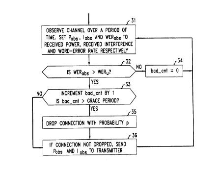
Figs. 3 and 4 show flow-charts illustrating a method of operation of a mobile radio
receiver and a mobile radio tr~msminer~ respectively, each operating in accordance with an
illustrative r.lllll~ - - of the present invention. Specifically, the illustrative procedure
shown in Fig. 3 may be used by a mobile radio rec eiver to monitor the channel quality of
20 its connection. In particular, step 31 observes the channel over a given period of time. and
set~s the observed power parameter (P,r.,r) to the received power, the observed interference
parameter (1"~,,) to the received interrerence, and the observed error rate p~rameter (l~ER"~,)
to the word-error rate. Step 32 compares the word-error rate to an upper tolerance limit
therefor (WER,), and, if the limit is exceeded, step 33 increments the count ~~f~5 " - .~ ly time fr,lmes (bad_cnf) and compares this count with the pl~d.t~l llull~d grace
period. If the count of llncr,~i~r~r tory time frames exceeds the grace period, step 35 drops
the connection witi~i a probability p. If the connection is not dropped, or if the grace period
is not exceeded. step 36 sends the observed power parameter imd the observed ill~tl ~ ,e
parameter to the transmitter.
The illustrative procedure shown in Fig. 4 is used by a mobile radio transmitter in
5 order to compute a new power-code pair when the above-described parameter data is
received from the receiver (thereby indicating that the connection is l~r~f i~f;~(~tory). The
new power-code pair computed by this procedure is based on the received parameter data.
Specificaily, step 41 performs normal transmit mode (i.e., continuing to transmit w;th the
same power-code pair) until step 42 determines that parameter data has been received from
10 the receiYer. Then, step 43 set~s parameter P, to the current transmit power and parameters
P~*i and 1~5 to the UUI.~ n~di~ values receiYed from the recei-~er. Step 44 computes the
received signai power (P,) and the received carrier-to ' r~ ratio (CIR~) based on
the parameter data received.
Then, steps 45 through 52 execute an iterative process (ie., a loop) for ~iP~Prminin~
15 a new power-code pair to be u.sed tor the given connection. In pa~ticular, each code in the
IJ.~d t..,~ c~i set of encoding schemes (c~ through c") is examinf d, in turn, to determine
the code which may be used with the least overall consumption of power (i.e., the power
consumed per inforn-iation bit) which 1l.,... ~h. 1. ~. satisfies the desired criteria (i.e., the
desired word-error rate and desired carrier-to-;.,t.,rtlc~ e ratio). The Code-~'ER tabie
20 (step 47) and equations (5) and (6) as described above (step 48) are adv~l.t..6~,u~1y used
to determine the required power for a given code, and the overall power consumption is
then determined (step 50) and compared to the various alternative code choices (step 51).
(Step 49 ensures that the given code does not require a power level which exceeds the
maximum lia~ 5:J~, capacity of the transmitter.) If, in fact, no acceptable power-code
25 pair can be found, step 54 causes the connection to be dropped. Other vise, step 55 sets the
(new) transmit power and the (new) transmit code ~ ;ly, and returns to step 41 lo
perform the signal ~ /111 in accordance therewith.
Although a specific r l,li,o ii.l..l,l of this invention has been shown and described
herein, it is to be understood that this embodiment is merely illustrative of the many
30 possible specific al, ~ which can be devised in application of the principles oF the
in~ention. For e~ample, the illustrative ~ i,o~ "1 described l1erein focused on systems
- ~ =
12
~ L' ?~
using forw~rd-error correction only, although the present inventive method can also be
used for systems using a combination of FEC and ARQ. Also by way of e~ample. even
though the illustrative embodiment herein described a distributed technique wherein each
individual transmitter-receiver pai} determined the ~ppropriate power-code pair to be used
S tor subsequent ~ , the pre~sent inventive method could be used with a
centralized technique in which a common (i.e., centralized) decision-nlaking process is
used to determine ~ lllib~;VII parameters for the various L~ t.~.,. The extension to
any such systems will be obvious to those skilled in the art. Numerous and varied other
'1l I "''L' '~" ~'f - can be devised in accordance with these principles by those of ordinary skill
10 in the art without departing from the spirit and scope of the invention.