Note: Descriptions are shown in the official language in which they were submitted.
~ 611~
OBJECT LOCATOR SYSTEM AND METHODS THEREFOR
Ei~ of the rnven~ n
The present invention relates generally to methods and systems for locating
objects. More po~ ulolly~ the present invention relates to using electronic tags to
5 locate objects such as documents.
r~ n~l of the TnvPn~ion
In ~,u~ liiullal systems for locating documerlts, documents are filed in assigned
places. When a document that is filed according to such a system is remoYed from its
assigned place, its location is usually unknown to persons other than the individual who
10 removed the document. If, after use, the document is re-filed in a place other than the
assigned place, it may be very difficult to located again.
In other more advanced filing systems, computers and database software are
used for document tracking. Ln such advanced systems, a document's location is
entered into a computer database, and, wheneYer the document is moved, the database
15 is updated a~,,ul ~ . Such a computer database system fails when items are misfiled,
movements are not recorded or i"ru, IlldLiull is incorrectly entered into the database. As
in the case of simpler filing sytems, if these or other filing errors occur, documents may
not be found at their e~pected locations and may be very difficult or impossible to
locate.
As such, there is a need for an improved rlli.. V~.'d~, location system.
Sllmm ~,v l-f the rnv~ntit~n
According to the present invention an electronic tag is used to locate an obiectsuch as a document. In one clllb~- ' t, an electronic tag is attached to a document
before filing the document. The electronic tag is identifiable by a unique response
25 code. Theresponsecodeand;,.r~"", ';.",pertainingtothedocumentareloggedand
the document is filed. To loc~te the document, the response code is entered into an
uv...vl. The i~ uv~ sends a sivnal which, in one ~".lb~d....~ , causes the tag
21~6~
to emit a sound. In other r~ , the i.lt~ ol emits a radio signal allowing
the user to locate the document. The present system thus allows for random storage
of documents and is also useful for locating misplaced documents.
Brief D.~cl~ription of th~ DMwi~c
Further features of the invention will become apparent from the following
detailed description of specific ~ Jodi~ thereof when read in, ; with the
dcc.ml~ iu~ drawings, in which like elements have like reference numerals and inwhich:
FIG. I is an exemplary ~. . ,1~).1:, ,1 of an object loc~tor system according tothe present invention;
FIG. 2 is a flow diagram illustrating a method for locating an object using the
system of FIG. I;
FIG. 3 is an illustration of a second ~ ,~li.. ,1 of an object locator system
according to the present invention wherein location markers are used;
FIG. 4 is an illustration of a third rl ~ 11 of an object locator system
according to the present invention,
FIG. S is a flow diagram illustrdting a method for locating an object using the
system of FIG. 4; and
FIG. 6 is an illustration of a fourth ~ odil~ of an object locator system
20 according to the present invention.
DPtril~fl l~crrir~ n nf ~h~ Invenril-n
The present invention provides methods and systems for locating objects such
as documents. Although the following description is primarily directed to locating
documents, it should be understood that the present invention may be used for locating
25 other objects, as well. It should also be appreciated that the receiving, i ~ or
locating devices used in .... j ., ... l ;, ." with the present invention are not intended to be
limited to any particular~.,.l.o.l;.,.. ~
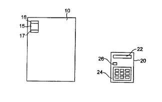
An ex~mplary object locator system for use in accordance with the present
~ ~ 96 , ~ o
in~ention is shown in FIG. 1. The exemplary system comprjses an electronic tag 15
and an interrogator 20. The electronic tag 15 is uniquely identified by a response or
identifier code. The electronic tag 15 is preferlbly physically adapted to be removably
attached to an object. such as document 10. For example, the electronic tag 15 can
5 include a piece of material 16 that can receive a staple so that the tag 15 may be stapled
to the document 10. Alternatively, a semi-sticky glue can be disposed on the material
16 or other portion of the tag 15. Preferably, the electronic tag 15 may further include
a peel-off sticker 17 that is marked with the response code of the tag. The response
code can appear on the sticker 17 as an alpha-numeric sequence, a bar code or in any
10 other suitable manner. Alternatively, the response code could be embossed on the body
of the tag 15 itself. The electronic tag 15 is preferably small, flat and thin so that a
"tagged" document uses a minimal amount of additional file space relative to an "un-
tagged'' document.
The illt~ U~ UI ~0 is operable, via appropriate circuitry, to detect and transmit
15 the response code of the electronic tag 1 5. The ;1.~ ,, 20 preferably includes a
display 22, an alpha-numeric key pad 24 and a transmit button 26. The response code
of the electronic tag 15 is entered, via the _', ' .._...~,ic keypad 24, into the
;IILcl ~u~S~lul 20. The entered code appears in the display 22. Once the user verifies
that the code is correct, the user then pushes the transmit button 26 causing the
20 ill~l.U~;UtU[ 20 to broadcast the response code of the electronic tag 15.
In one e.~l ' t~ the electronic tag 15 includes circuitry suitable for an
active response by the tag, i.e., the tag emits a sound, when its response code is
broadcast. In another I ....l ~l;, . ~ . the electronic tag 15 includes circuitry suitably
conf gured for a passive response by the tag, i.e., the tag 15 modulates its reflection of
25 the illLcl~u;;~n's radio signal. If the tag is passive, the ill;~llU;~; 'Ul 20 should include
a receiver and other circuitry suitable for actively locating the tag 15. For example, in
one ~" ,l .- . l; " ,. . ,l such locating circuitry enables the i..~l l~ ,, ' 20 to emit a sound
which changes in frequency or some other manner to indicate relative proxirnity to the
tag 15. In other C ~ the locating circuitry causes the i.lt~,.lUI5~Lu. display 22
30 tû pro\~ide a \lisual indication of tag proximity, such as signal strength, o~ an indic~tion
r 1 ~ ~
of distance to the tag l5. The design and ;,.,~ .. of such active and passive
tags and locating circuitry is within the capabilities of those skilled in the art.
A method fo} locating an object with the electronic tag 15 and il.t. ..uo.llul 20
is shown in FIG. 2. In the Following discussion, the object will be assumed to be a
S document, such as the document 10. A user attaches the electronic tag 15 to the
document 10, for example by stapling, as indicated in operation block 100. In
operation block 110, the tag's response code and document ' ~U~ tiOl~ are recorded in
a storage device. In one ~lllbodill~.lL, the storage device is a log book, and the peel-off
sticker 17 is removed from the tag and stored in the log book with i..~lllldLio..
10 pertaining to the document 10. In other emho~iml~nt~ the storage device can be a
computer storage medium, such as a floppy disk or hard drive. If the response code is
in the form of a bar code, a bar code reader can be connected to a computer so that the
code is read by the reader and transmitted to the computer and s~ored in an appropriate
entry on the floppy disk or hard drive. Alternatively, in a further c..~l.o~l' .;, the tag
15 15 is suitably con~;gured to allow it to be ~-~vOl~ with a response code at the time
of its use. After the electronic tag 15 is attached to the document 10, and the tag's
response code and document ii.r~ iu.. are recorded, the document can be filed in a
filing cabinet, such as the filing cabinet 5 of FIG. 3 or some other suitable document
storage apparatus.
To locate the tagged document 10 in storage, the response code for the tag 15
is entered into the ill.~ .l 20 as indicated in operation block 120. Depending
upon the specific electronic u~rlOul,~ ll of the tag and il.~l-- O , as discussed
above, one of either the tag 15 or the i..t~".uo.lLo. 20 will provide an indication of the
tag's location and hence the location of the document 10, as noted in operation block
25 130. Using the present metnod, documents can be filed randomly as filing space
permits. Further, the present invention provides a means for locating a document that
has been improperly filed in an organized filing system.
In a furthem,llll~dilll~,lll, an object locator system according to the present
invention also includes location markers. In FIG. 3, location markers 31, 32, are
30 shown pl~Lced in the filing cabinet 5. While two location m~rkers are shown in FIG. 3,
~ 219611~
more or less of such markers can be used depending on the size of the file sto~age
equipment. Location markers are preferably larger than the electronic tag 15, powered
and suitably shaped for the particular ~pl ir~iir,n For example, if the location markers
31 and 32 will be used in a filing cabinet, such as the filing cabinet 5, they should be
S relatively thin and sized to fit within a typical file drawer. In one ~ lI,od;l~ , the
electronic tag 15 is suitably configured so that when its response code is ir~ncmir~1
the tag 15 sends a signal that causes location markers in the vicinity, such as location
markers 31 and 32, to emit a sound. Once the activated location markers are located,
a manual search can be performed to Fmd the document of interest or an automatic10 search can continue more rapidly with the user now focused on the generai location of
the document 10.
Alternatively, the electronic tag 15 can be configured so that when its responsecode is i i, the tag 15 sends a signai to, or receives a signal from, a locationmarker, and then sends a signal to a suitably conFlgured ~ llu~;~tul 20, which signal is
15 indicative of the proximity of the electronic tag 15 to the location marker. Thus, a
message such as "5 inches from LM3 1 " can be provided in the display 22 of the
llU~ U- 20 indicating that the document of interest is 5 inches from location
marker 31. In a further . ~ . ,1~.~.1: ., .. l the location marker, such as location marker 31
or 32 can send a signal to the ilit~ V~_ Ol 20 indicative of the proximity of the
20 electronic tag 15. Means for ,i. ~ the proximity of the electronic tag 15 to the
location marker 31 or 32 can be located in the i..~,.lU~ VI 20, electronic tag 15, the
location mark~rs or in a separate device. As will be appreciated by those skilled in the
art, various methods are available for ' ~ the proximity of the taB to the
location marker. If, for example, the tag l 5 contains a radio receiver, it can measure
25 the strength of a radio signal received from the location marker. Knowledge of how
much power is transmitted by the location marker and the received signal strenglh
allows calculation of the distance from the electronic tag 15 to the location marker 31.
The tag can then transmit the calculated distance to tbe il~t~.lU~..tVI 20, or transmit a
signal indicative of the received signal skength information to khe ill;~,llU~ UI, which
30 can then c~lculate the disbmce from the location marker to the tag. The design and
~ ~ 1 9 f~
l of such means are within the capabilities of those skilled in the art.
In a further ~ o I;~ IL, an object locator system according to the present
invention includes a processor or computer, as shown in FIGS. 4 and 6. The computer
is accessed for record storage as well as for processing functions. Illcùl~ula~ g a
5 computer in the object locator system is particularly a ;i~a~ u~ in :~rrl j~r jon~
where files include textual information suitable for storage in computer records as well
other material that is not as well suited to computer storage. For example, a computer
storage medium may suitably be used to store a patient's medical records. To theextent x-rays or other visual medical scans can be digitized and ~ lv~ lly stored, it
10 may also be desirable to maintain hard copies of the original visual media.
In the ~.lllb~ '' ' shown in FIG. 4, a processor 40 is in .,u with
an IU~ UI 21 comprising a transmitter 23a and a receiver 23b. Though shown
illcul~la~d into the illl~llu" ~.( 21 in FIG. 4, it should be al""c- ' that the
transmitter 23a and receiver 23b may be separate devices. Textual material from a
15 record, such as, ~vithout limitation, a patient's medical record, can be kept on a
computer storage means such as floppy disks, a hard drive or other suitable memory
device associated with the processor 40. If, however, an x-ray 11 or other
~llulu~la~ll;c material torm part of the patient's record, physical storage of such
material may be desirable. A t'urther . ., .1 ,o. 1; . . ' of a method for locating an object,
20 directed to the object locator system shown in FIG. 4, is presented in FIG. 5.
As indicated in operation block 200, an electronic tag 15 is attached to an
object, such as the x-ray 11. A record is formed containing the response code for the
tag 15 and illru~ ioll concerning the tagged obiect, as shown in operation block 210.
The record is stored in a computer storage means, as indicated in operation block 220.
25 In the present example of medical records, the record created in operation block 210
may form part of a patient's medical record. The x-ray 11 may then be filed in aphysical storage container, such as the filing cabinet 5, near location markers, such as
the location markers 31 and 32. The ~ ,~".I...r. ;,. ~1 record may then be queried for the
location of the object, i.e., the x-ray 11, as indicated in operation block 230. Once
30 queried, the processor, in operation block 240, directs the transmitter 23a to transmit
3~ J;~ '! b
i
the response codo for the tag 15. As indicated in operation block 250, a signal is
returned to the receiver 23b indicative of the tag's position relative to one or more
location markers, which, in the present illustration, are markers 31 and 32. The tag~s
location can then be displayed on the display device 41 as indicated in operation block
5 260.
In another ~ illustrated in FIG. 6, the electronic tag 15 can be
attached to a folder 50 for retaining documents. Each document that is to be stored in
the folder 50 has an identifier labol 'i2 providing an i~ code. As a document
is placed in, or removed from the folder 50, it is scanned by a reador 54 capable of
10 readingthe~ "ir..~ ;,.codefromthelabel52~ Thereader54isin~
with a processor, such as the processor 40. A computer record is ~ ly
generated and maintained of the documents placed in, or removed from, the folder 50.
The record also contains the response code of the electronic tag 15. Thus, to locate a
document, a suitably l~lv~ d processor 40 identifies the folder 50 in which the
15 document resides. An indication is provided as to whether the document is in the
folder. Further, the processor directs the transmitter 23a to transmit the response code
for the tag 15. A signal is returned to the receiver 23b indicative of the tag's position
relative to one or more location markers 31 and 32. The tag's location can then be
displayed on the display device 41. The identifier label 52 and reader 54 can be a bar
20 code and bar code reader, a printed label scanned by an optical character recognition
system, a label with an i, l. .~l ;r;~ codo read by a short range l~l~"~ h~l and the
like.
The electronic tag 15 used in .~.. .; I ;- ", with the present invention can bo,without limitation, a low frequency tag using inductive coupling or a radio frequency
25 IRF) tag using modulated backscatter.
The following non-limiting examples are presented to further illustrate the
features and benefits of the present methods and systems.
EXAMPLE I - Random Filing of Documents
A group medical practice may have thousands of patient files. After a period of
O
time, marly of such files may be discarded as patients no longer patronize the group
practice. Further, over time, additional ~ may join the group practice,
bringing within them many additional patient files. Rather than ~v~L g the filing
system, it may be convenient to add the files to filing cabinets as space permits. The
present invention may be used for this purpose as described below.
An electronic tag 15 is attached to a new patient file. The tag's response cocie,
and the patient' s name are recorded in a log such as a notebook or a computer record.
The file is then placed in a filing cabinet as space permits. To retrieve the file, the log
is consulted to obtain the response code of the tag 15 attached to the patient's file. The
response code is entered into a interrogator, and the tag provides an indication of its
location in any of the previously described ways depending upon the particulars of the
locator system.
EXAMPLE 2 - Locating an Incorrectly Filed Document
Filing systems may be organized in a variety of ways. For example, files may be
given a numerical designation and filed in numerical order, or they may be ', ' ' I
by subject matter or by a client's or patient's name, to mention a few. When a file is
mis-filed in such a system, it may require an extensive and time-consuming search to
locate it. The methods and systems of the present invention can be used to simplify the
task of locating a mis-filed document as described below.
A file is to be filed in a numerical filing system. An electronic tag 15 is attached
to the file. The tag's response code, and a description of the file are recorded in a log
such as a notebook or a computer record. The file, which was intended to be
filed, is mis-filed. To later locate the file, the log is consulted to obtain the
response code of the tag 15 attached to the file. The response code is entered into an
illLcllv~ u-, and the tag provides an indication of its location in arly of the previously
described ways depending upon the particulars of the locator system.
The foregoing examples and ~ .. .1 ,vi i ;. . .. ~ of the present invention are
illustrative of the principles of this invention and are not intended to limit the invention
in any way. It will hc further appreciated that various ll.ùdili.atiolls may occur to those
~ q 5 6
skilled in the art in vie v of the pre~sent teachings without departing from the scope and
spirit of the invention.