Note: Descriptions are shown in the official language in which they were submitted.
2~ ~~~ 4a
_ 1 _
ROUTING SYSTEM
BACKGROUND OF THE INVENTION
1. Field of the Invention:
The present invention relates to packet switching
communication and ATM switching communication, and
particularly to a routing control system.
2. Description of the Related Art:
In connection-oriented communication as represent-
ed by ATM (Asynchronous Transfer Mode), one connection
is established in one manner at the time of setting up
a call and no change is allowed during a call. The
application program communicates to the base (communi-
cation partner) using this ATM connection. Here, as
one means of altering a route in response to congestive
state in the network, one routing control method has
been proposed by which a plurality of connections from
source to destination are set up independently and the
connections employed are altered for every information
unit (message). The selection of connections at this
time is executed only at the transmission node which is
the information source. Devices such as terminals,
information transfer servers, and routers that become
information sources and transmit ini=ormation are here-
inbelow referred to as "transmission terminals."
r ;
d L., ~ ~' ~~
_ 2 _
In a case in which a transmission terminal
transmits an information group made up of a plurality
of information units from source to destination by a
plurality of routes using a plurality of connections,
one connection is used for each information unit trans-
mitted. The plurality of connections that are set up
for transmitting from source to destination by a plu-
rality of routes are called the same connection group.
At this time, the ID of the VC (virtual channel)
(hereinbelow referred to as "VCI"), or the ID of the VP
(virtual path) (hereinbelow referred to as "VPI"),
which are the identifiers of each connection, is
required at each link (segment) between connection
nodes.
Fig. 1 shows a routing table :Eor a routing system
of the prior art. In the routing table shown in Fig.
1, the input-side VCI are mapped to the output-side
VCI. In other words, this table is a correspondence
table such that VCI or VPI which are the ID of input
packets (hereinbelow referred to simply as "input-side
VCI"), are rewritten as the VCI or VPI which are the ID
of output packets (hereinbelow referred to simply as
"output-side VCI"). This means that, for example, a
packet for which input side VCI = 1.00 is rewritten as
output side VCI = 200 and outputted from the switch.
In Fig. 1, one input-side VCI is mapped to one output-
~~ ~~~~ ~0
_ 3 _
side VCI.
The first problem of the above-described prior art
is the occurrence of a reduction-in network throughput
and communication quality degradation including delays
and cell loss.
The cause of this problem is that, in general,
when a network is very large, transmission nodes cannot
accurately detect congestive states in the network, due
to propagation delay and other factors, so that dynamic
selection of optimum routes for good routing efficiency
cannot be expected.
A second problem of the prior art is that the VCI
and VPI required at each link (segment) between
connection nodes are consumed in large volumes due to
the plurality of connections used.
The reason for this is that only a limited number
of these VCI and VPI are prepared, and, due to the
concern that VCI and VPI will be exhausted because of
the plurality of VCI and VPI consumed when using a
plurality of connections, VCI and VPI must be conserved
to ensure effective use of the network.
SUMMARY OF THE INVENTION
In view of these problems of the prior art, the
object of the present invention is to provide a routing
system that can bring about an improvement of
~ , ~t ~ 1
~'~.ia..,i~~~
-
throughput of a network as well as an improvement of
communication quality, and moreover, that enables
conservation of connection identifiers.
The routing system of the present invention is a
routing control system that, for each call, sets up a
plurality of connections in advance of transmission of
information, selects one connection from this plurality
of connections for each unit of transmission informa-
tion, and then transmits the units of transmission
information. The plurality of connections are not
changed for sections in which the :routes to be taken
are different but are consolidated into one connection
for sections in which the routes to be taken are the
same; and a connecting device provided at the node,
which are set up for a pluralii~y of connections to
either or to both the input and output sides, discre-
tionary makes either a first connection, which is
either the plurality of connections or one consolidated
connection, to the input side, or a second connection,
which is either the plurality of connections or one
consolidated connection, to the output side.
According to the routing system of the present
invention as described hereinabove, the connecting
device changes connecting relationship between the
first connection and the second connection for every
unit of the transmission information in accordance with
~~~~~4~0
- 5 -
information held by the node indicating either or both
the congestive state and the load conditions of a
network.
According to the above-described routing system of
the present invention, the connecting device can cause
connecting relationship between the first connection
and the second connection to change in accordance with
the connecting information held by each individual
packet of the units of transmission information.
According to the above-described routing system of
the present invention, a transmission terminal, which
is the source of transmitted information, determines
the routing and writes routing information into each
individual packet for each transmission information
unit; and the connecting device is capable of perform-
ing.routing using the routing information designated by
the transmission terminal.
According to the above-described routing system of
the present invention, the method of consolidating
routing information at the time of setting up
connections is such that, after setting up each
connection without consolidating connections, a plural-
ity of connections at each node having~a same destina-
tion can be consolidated as one connection, and the
identifiers of the consequently unused connections can
be saved to unused connection identifiers.
_ 6 -
According to the above-described routing system of
the present invention, a routing procedure at the time
of setting up connections is such that, in setting up a
plurality of connections at individual node, when there
is the second connection set up for a destination which
is the same as that of the,first cannection already set
up at the node, the connection identifier of the first
connection is mapped to the second connection and each
plurality of connections is set up as one consolidated
connection.
(1) The plurality of connections existing in
parallel in the prior art are concentrated to one
connection, and information is communicated using the
one concentrated connection. As a result, a single
connection identifier is sufficient for a plurality of
connections, and the number of connection identifiers
used on the entire network can be reduced. In other
words, a multiplicity of routes can be switched by the
nodes of a network using only a small number of con-
nection identifiers, and load dispersion can be effec-
tively carried out by routing.
For example, although the prior-art system
required 100 VCI in a case in which 100 connections of
the same connection group use the same link, just one
VCI is sufficient for the present invention, thereby
allowing a great reduction in the use of VCI.
~~ ~~~~ ~0
In addition, rebranching of connection to a plu-
rality of routes from a concentrated connection can be
realized while the transmission terminal manages
routes.
(2) Instead of the transmission terminal deter-
mining the route by which information is to be sent at
the time of transmission as in the prior art, when a
packet arrives at a node which decides the routing, the
node uses the information it has indicating the load
state and congestive state of the network together with
the information contained in the packet determined by
the repeater nodes, and can by using the most recent
information control the routing in accordance with the
state of the network. In other words, when nodes
decide the routing, links having low use can be select-
ed and congested connections avoided, thereby improving
network throughput and communications quality.
For example, for a case in which the one-way
propagation~delay between a sending side and receiving
side is 100 msec, and in which intermediate nodes exist
for routes distribution, a delay of at least 100 msec
is necessary for the sending side to be alerted of
congestion occurring in the vicinity of the receiving
side. However, for congestion occurring at intermedi-
ate nodes, the sending side can be alerted after a
delay of only 50 msec, so that congestion can be dealt
CA 02196140 2000-09-25
74570-54
_ g
with effectively 50 msec sooner.
(3) By providing a procedure for identifying a
plurality of connections on the same connection group, a table
can be produced for concentrating the plurality of connections.
Using more recent network information allows
information to be sent by the optimum route, brings about an
improvement in network throughput, an improvement in
communication quality, and moreover, conservation of connection
identifiers.
In accordance with the present invention, there is
provided a routing system for establishing a plurality of
connections having Virtual Channel Identifiers (VCIs) or
Virtual Path Identifiers (VPIs) for each call between a
transmission terminal and a reception terminal through a
plurality of nodes prior to transmission of information from
said transmission terminal to said reception terminal, and for
selecting one connection from among said plurality of
connections for each unit of information; said routing system
comprising: means provided at at least one of said nodes, for a
section where all of said connections take different routes,
for establishing said connections without changing the routes,
and for a section where at least two connections take the same
route, for combining said connections that take the same route
into a combined connection having one VCI or VPI; and means
provided at at least one of said nodes, for making arbitrary
connections between a first connection at an input side of said
at least one of said nodes which is a combined connection or is
selected from a plurality of connections, and a second
connection at an output side of said at least one of said nodes
which is a combined connection or is selected from a plurality
of connections.
CA 02196140 2000-09-25
74570-54
- 8a -
The above and other objects, features, and advantages
of the present invention will become apparent from the
following description based on the accompanying drawings which
illustrate examples of preferred embodiments of the present
invention.
BRIEF DESCRIPTION OF THE DRAWINGS
Fig. 1 shows a routing table in a routing system of
the prior art.
Fig. 2 shows the structure of a routing device in
which the routing system of the present invention is applied.
Fig. 3 shows a routing table in the first embodiment
of the present invention.
Fig. 4 is a conceptual view of the procedure in the
first embodiment of the present invention.
_ g _
Fig. 5 shows a routing table in the second embodi-
ment of the present invention.
Fig. 6 shows a routing table in the second embodi-
ment of the present invention.
Fig. 7 is a conceptual view of the procedures in
the second embodiment of the present invention.
DETAILED DESCRIPTION OF THE PREFERRED EMBODIMENTS
Embodiments of the present invention will next be
explained with reference to the accompanying figures.
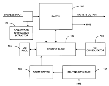
Fig. 2 shows the structure of a routing device in
which the routing system of the present invention is
applied.
In the routing system according to the present
invention, packets and ATM cells (hereinbelow referred
to as simply "packets") are distributed between routes
using a routing device (hereinbelow referred to as
simply "node") including a switch as shown in FIg. 2, a
cross-connector, and other components.
The node shown in Fig. 2 includes switch 101,
routing table 102, route switch 103, routing data base
104, VCI (Virtual Channel Identifier) pool 105, VCI
consolidator 106, and connecting information extractor
107.
In Fig. 2, when packets belonging to a connection
already set up are inputted, the inputted packets are
2~ '~61 ~~
- to -
copied to connecting information extractor 107 where
header information is extracted, and then the packets
are switched at switch 101. The header information
extracted at connecting information extractor 107 is
inputted to routing table 102, and the switch destina-
tions of inputted packets are communicated to switch
101 based on the header information.
In addition, at the time of setting up
connections, routing table I02 uses unused VCI numbers
stored in VCI pool 105 at connections having set-up
requests, and these VCI numbers are set to an "in use"
state. When a connection is cut, the VCI numbers used
at the connection that is cut are set to an "unused"
state in VCI pool 105.
In working the present invention, the connection
set-up procedure of the ATM requires no special proce-
dures other than those of the prior art.
The present invention is distinguished by the
mapping methods of the input cell ID and output cell ID
in the routing table, and therefore, when setting up
connections, any prior-art connection set-up procedure
may be employed that stipulates a one-to-one mapping of
input cell ID (input side VCI) and output cell ID
(output-side~VCI) in the routing table. UNI Spec. 3:1
as stipulated by The ATM Forum is one example of such a
connection set-up procedure. In this case, connections
_ 11 _ .~ C~ ~ d
are set up one by one in succession when setting up a
plurality of connections from source to destination.
However, a set-up procedure that requires that the
plurality of connections be set up simultaneously is
also possible. To simplify the explanation in each of
the embodiments of the present invention, the setting
of routing tables at each node is carried out for each
connection set-up request in the order of arrival.
[First Embodiment]
The first embodiment of the present invention
relates to a routing table.
Fig. 3 shows a routing table in the first
embodiment of the present invention, and shows routing
table 102 of the node shown in Fig., 2.
In the prior-art routing table shown in Fig. 1,
one input-side VCI inputted to switch lOl shown in Fig.
2 is mapped to one output-side VCI. The routing table
of the first embodiment shown in Fig. 3, however, is'
constructed such that a plurality of input-side VCI are
mapped to a single output-side VCI. In other words,
input-side VCI = 100, 101, 102 are mapped to output-
side VCI = 200, and input-side VCI = 103, 104, 105 are
mapped to output-side VCI = 201.
Fig. 4 shows a conceptual view of the procedure of
the first embodiment of the present invention, and
w.~b. ~ - 12 -
presents a comparison of the results of setting up
connections using the. routing table shown in Fig. 3 and
the results obtained using the routing table shown in
Fig. 1.
[Second Embodiment]
In the same way as the first embodiment, the
second embodiment of the present invention relates to a
routing table and illustrates a case in which routes
are switched based on an activity indicator.
Fig. 5 and Fig. 6 show a routing table for the
second embodiment of the present invention and a rout-
ing table 102 of the node shown in Fig. 2.
Fig. 5 shows the routing table for a node which
used connection A and connection B of the same connec-
tion group. In Fig. 5, input-side VCI - 100 is mapped
to output-side VCI = 200, 201, 202 for connection A,
and input-side VCI = 101 is mapped to output-side VCI =
203, 204, 205 for connection B. At this time, mapping
of input-side and output-side VCI in the routing table
shown in Fig. 5 is performed as follows. For connec-
tion A, any of the values VCI = 200, 201, 202 can be
taken as output-side VCI for input-side VCI = 100. The
value that is taken is determined by the ON or OFF
state (corresponding to "1" and "0," respectively, in
Fig. 5) of an activity indicator (hereinbelow referred
~~ 9~~ ~o
- 13 -
to ws "AI"), which is a symbol attached to each of
output-side VCI = 200, 201, 202 of connection A.
Regarding the AI of this connection A, an ON state of
only one AI of the output-side VCI indicates that this
output-side VCI is to be used, and OFF states of all of
the AI of the remaining output-side VCI indicate that
these output-side VCI are not to be used. In connec-
tion B as well, each output-side VCI for use by connec-
tion B has an AI, and the operation is equivalent to
that of connection A. Fig. 5 shows a situation in
which the input-side VCI of connection A is mapped to
output-side VCI = 200, and the input-.side VCI of con-
nection B is mapped to output-side VCI = 204. The
switching of ON/OFF states of these AI is performed by
route switch 103 shown in Fig. 2.
Fig. 6 shows a case in which, after consolidating
the routes of a plurality of connections using the
procedure described in the first embodiment, these
routes are again branched using the procedure of the
second embodiment. Connection A in Fig. 6 is assigned
input-side VCI = 100 or 101. At this time, input-side
VCI is the output-side VCI in the routing table de-
scribed in the first embodiment, which is the output of
the node of the preceding section. The value that is
taken in input-side VCI is determined by the procedure
described in the first embodiment in the routing table
:~ 2~9~1"~~
- 14 -
of the node of the preceding section. For connection
A, the input-side VCI are mapped output-side VCI = 200,
201, 202 regardless of the value of the input-side VCI.
In other words, any of the values output-side VCI =
200, 201, 202 can be taken whether input-side VCI = 100
or input-side VCI = 101. The same as the case shown in
Fig. 5, the value taken is determined by the ON/OFF
state (corresponding to "1" and "0", respectively, in
Fig. 6) of the AI attached to each,of output-side VCI =
200, 201, 202 of connection A. Regarding these AI, in
output-side VCI = 200"202, the ON state of only one AI
of the output-side VCI for each input-side VCI indi-
cates that this output-side VCI is to be used, and OFF
states in all AI of the remaining output-side VCI
indicate that these output-side VCI are not to be used.
Fig. 6 shows the situation in which input-side VCI =
100 is mapped to output-side VCI = 201, and input-side
VCI = 101 is mapped to output-side VCI = 200.
Fig. 7 is a conceptual view of the procedure in
the second embodiment of the present invention. Fig.
7(A) presents a comparison of the results of setting up
connections using the routing table shown in Fig. 5 and
the results of setting up connections using the routing
table shown in Fig. 1. Fig. 7(B) shows a comparison of
the results of setting up connections using the routing
table shown in Fig. 6 and the results of setting up
,~. 21 '~ ~ ~ 4 0
- 15 -
connections using the routing table shown in Fig. 1.
[Third Embodiment)
The third embodiment of the present invention
shows a case in which AI of the routing table described
in the second embodiment is set up indirectly according
to congestive information of a network managed by a
routing data base.
Congestive information of a network described in
the second embodiment can conceivably include such
items as load, vacant bands, degree of congestion, cell
loss rate, and cell delay times. In addition to these
items, an index indicating the load state of the net-
work can also be used. Routes are selected based on
these indices according to a procedure that-is deter-
mined beforehand at route switch 103. For example. a
selection algorithm may be used by which routes having
the lowest rate of use are selected.
Route switch 103 selects the optimum route at each
connection using any of the information contained
within the information on congestion of the network
that is extracted from routing data base 104, which
manages information indicating the congestive state of
the network as the .optimum routing information. Rout-
ing data base 104 may be any device that reflects the
load state of the network. As one example, an ABR
~~ ~~~ ~o
F
- 16 -
control procedure described in Draft specification ATM
Forum 94-047188 of The ATM Forum (March 1995) discloses
an.ER rate within an RM cell designated for each con-
nection, and this ER rate may be used as data indicat-
ing the congestive state of a route by which the RM
cell was sent.
[Fourth Embodiment]
The fourth embodiment of the present invention
presents a case in which the AI of the routing table
described in the second embodiment are setup using
network congestive information held by the packets
themselves.
In the fourth embodiment, route switch 103 ex-
tracts some of the congestive information not from
routing data base 104 described in the second embodi-
ment, but from arriving packets, and based on this
information, selects the optimum route for each connec-
tion. After determining routes, this determined rout-
ing is maintained as long as no information for route
determination (route updating) is recorded in newly
received packets. This congestive information may
include such factors as load, vacant bands, degree of
congestion, cell loss rate, and cell delay times. In
addition, indices indicating load conditions in the
network may also be used. These indices may be re-
2~ 9140
_ 17 _
ceived from, for example, a network management system
(NMS) by way of routing data base 104. The route
selection based on these indices is carried out accord-
ing to a predetermined procedure at route switch 103.
For example, an algorithm may be used that results in
selection of routes in which no congestion occurs.
Alternatively, the transmission terminal may designate
which route is to selected based on these indices and
record this information in packets to execute selec-
tion. Packets would be required to carry information
indicating network congestive state or load conditions,
and one possible method of conveying this information
is, for example, to confer ER information to RM cells
as described in Draft Specification ATM Forum 95-001388
of The ATM Forum (October 1995).
[Fifth Embodiment]
The fifth embodiment of the present invention
presents a case in which the AI of the routing table
described in the second embodiment are set up using
network connecting information held by the packets
themselves. In the fifth embodiment, route switch 103
extracts information not from routing data base 104
described in'the second embodiment, but from arriving
packets. In addition, the extracted information is not
congestive information described in the fourth embodi-
2~9~~~
- 18 -
ment, but connecting information. After the arrival of
a packet, route switch 103 routes subsequent packets
based on the extracted connecting information. This
connecting information is designated at the time of
transmitting information by the transmission terminal
that is the source of transmitted information and
recorded in the packets. Connecting information ex-
tractor 107 extracts this connecting information from
arriving packets and forwards it to routing table 102.
[Sixth Embodiment]
The sixth embodiment of the present invention
relates to the set-up procedure of the routing table
described in the first embodiment.
According to the sixth embodiment, when setting up
a connection, VCI consolidator 106 shown in Fig. 2
searches all connecting data of the routing table after
obtaining input-side VCI and output-side VCI, and when
a connection (connection B) is discovered in the same
connection group as that set up for the next target
node of the connection (connection A), changes the
output-side VCI of connection A to the output-side VCI
of connection B. In addition, it returns the output-
side VCI number of connection A to VCI pool 105, which
manages unused output-side VCI numbers, and sets it to
an unused state.
~~ ~~ l '~~
- 19 -
For example, when connection B input-side VCI =
100 is mapped to output-side VCI = 20~, input-side VCI
- 101 is mapped to output-side VCI = 202 immediately
after setting up connection A as shown in Fig. 1.
However, when VCI consolidator 106 operates immediately
after setting up connection A, connection A input-side
VCI = 101 is mapped to output-side VCI = 200. This
result is the same as the routing table shown in Fig.
3.
[Seventh Embodiment)
The seventh embodiment of the present invention
relates to the set-up procedure of the routing table
described in the first embodiment.
In the seventh embodiment, when setting up a con-
nection, VCI consolidator 106 shown in Fig. 2 searches
all connecting data of the routing table before obtain-
ing input-side VCI and output-side VCI. Then, when a
connection (connection B) is discovered in the same
connection group as that set up for the next target
node of the connection (connection A), VCI consolidator
106 makes the output-side VCI of connection A the same
as the output-side VCI of connection B.
For example, if connection A has already been set
up and its input-side VCI = 100 is mapped to output-
side VCI = 200, output-side VCI = 200 is mapped to
_ 20 _ ~~~~~~~-0
input-side VCI = 101 for connection B of the same
connection group. Moreover, output-side VCI = 200 is
mapped to-input-side VCI = 102 for connection C of the
same connection group. The result is the same as the
routing table shown in Fig. 3.
It is to be understood, however, that although the
characteristics and advantages of the present invention
have been set forth in the foregoing description, the
disclosure is illustrative only, and changes may be
made in the arrangement of the parts within the scope
of the appended claims.