Note: Descriptions are shown in the official language in which they were submitted.
2196217
WO 96/04065 PCT/EP95/02725
Adsorption reactor for separating undesirable
components from a fluid
The invention relates to an adsorption reactor
for separating undesirable components from a fluid, in
particular from an exhaust gas, having at least one
reaction chamber which has feeding means at the top and
funnel-shaped discharge means at the bottom for feeding
and for discharging an adsorbent in lumps or in granular
form.
DE-A 26 26 939 shows a device of the generic
type, in which the fluid inside the reaction space is
conducted through two layers traveling parallel to one
another, and the adsorbent is moved at a higher speed in
the downstream layer and is loaded to a lesser extent
than in the layer on the upstream side. This known device
is intended to carry out thorough purification of the
exhaust gas as far as possible since sufficiently fresh
adsorbent is still applied to the exhaust gas on the
downstream side. On the other hand, adsorbent which has
only been utilized to a very limited extent must con-
stantly be discharged and regenerated in a relatively
thick layer on the downstream side. The reaction chamber
is subdivided by vertical partitions. The individual
compartments are provided with adsorbent from a central
filling opening and have discharge openings or funnels
assigned to the individual layers.
It is known from DE-C 34 27 905 to even out the
adsorbent particle flow by means of baffles over the
2196217
WO 96/04065 - 2 - PCT/EP95/02725
cross section of the traveling bed.
In known adsorption equipment, significant parts,
in particular, of the pile of bulk material in the top
region and of the discharge pile in the bottom region of
the reactor cannot or cannot satisfactorily be reached by
the transversely flowing fluid. The consequence of this
ranges from hot spots (heat concentrations) to sources of
fire in the top region and accumulations of condensate,
in conjunction with caked-on particles in the bottom
region of the reactor. Furthermore, difficulties arise in
the region where the fluid flows off since, on the one
hand, the adsorbent is to be retained and, on the other
hand, obstructions to the fluid flow should be minimized.
The invention is based on the object of providing
improved flow of the fluid to be treated through the
adsorbent bed and of avoiding operational malfunctions,
in particular in the critical top and discharge regions
of the adsorber and the fluid flow.
To achieve this object, the adsorption reactor
according to the invention is defined by the fact that
the feeding means are formed by a grid of a plurality of
feeding funnels arranged adjacently and one behind
another, and the discharge means are formed by a further
grid of discharge funnels arranged adjacently and one
behind another; that fluid passages are provided both at
least in one downstream shutter wall and in the top
region of the reaction chamber; and that the downstream
shutter wall has, in a sandwich-type construction on the
upstream side, a slotted hole screen with slot-bounding
CA 02196217 2000-03-07
3
elements running essentially parallel, then a stabilizing
grid with connecting elements running transversely to the
slot-bounding elements, and, on the downstream side, a
shutter construction with louvers running transversely to
the slot-bounding elements.
According to the present invention, there is
provided an adsorption reactor for separating undesirable
components from a fluid, having at least one reaction
chamber (202) which has feeding means at the top and
funnel-shaped discharge means at the bottom for feeding and
for discharging an adsorbent in lumps or in granular form,
the reaction chamber (202) being arranged in a housing
(201) and being bounded by parallel vertical shutters
(203) ,
the feeding means having:
- a feed container (204), arranged above the reaction
chamber (202), for the adsorbent, and
- a distributing bottom, formed by a plurality of
feeding funnels (205), between the feed container (204) and
the reaction chamber (202),
the discharge means having a discharge bottom which is
formed by a plurality of delivery funnels (207) and is
arranged below the reaction chamber (202) between the
latter and a delivery container (206) for the adsorbent,
the delivery funnels (207) being arranged within a region
the housing (201), adjoining reaction chambers having
regions where the delivery funnels (207) are arranged in
fluid communication with each other,
a fluid inlet (208) leading into the housing (201) in said
region of the housing where the delivery funnels (207) are
arranged,
CA 02196217 2000-03-07
t
3a
a lower wall (209) being arranged at the height of the
discharge bottom to one side of the reaction chamber (202)
between the- latter and the housing (201) or an adjacent
reaction chamber (202), which lower wall allows the fluid
to flow around the discharge funnels (207),
an upper wall (210) being arranged in the region of the
distributing bottom to the other side of the reaction
chamber (202) between the latter and the housing (201) or
an adjacent reaction chamber (202), which upper wall allows
the fluid to flow around the feeding funnels (205),
the feed container (204) being arranged within the housing
(201), at least one feed pipe (212) for adsorbent leading
out of the housing (201), and
a fluid outlet (211) leading out of the housing (201) in
the region of the feed container (204),
wherein a plurality of reaction chambers (202) adjoin one
another transversely to the throughflow direction and are
provided with a common feed container (204) and delivery
container (206), and
wherein a delivery device is arranged between the discharge
funnels (207) and the elongate delivery container (206),
which delivery device is common to the mutually adjoining
reaction chambers (202) and has at least one delivery rake
(215) which can be moved transversely to the throughflow
direction.
Structuring the feeding and discharge regions of
the adsorbent into a large number of conical partial
regioas minimizes the material pockets is the top, and
bottom regions of the reactor which are difficult for~the
fluid flow to reach. Moreover the particle flow aad
mechanism of the bulk material inside the reaction space
CA 02196217 2000-03-07
3b
are improved both during feeding and duriag discharge of
the adsorbent by the structure into part-flows. Although
the main flow of the fluid is directed traasversely to
the column of adsorbent. fresh adsorbeat in the top
region of the reactor is increasingly involved in the
reaction due to the fluid conducted into the reaction
space or out of the reaction space in that area.
The slotted hole screen forms a virtually smooth,
disturbance-free surface, along which the partiele flow
of the adsorbent can flow from the top, to the bottom
essentially in oae plane. Particles of normal size are
retained by the wall on the upstream side. In contrast,
the fluid flow is allowed to pass through virtually
unobstructed over the entire height of the shutter wall.
The crossover arrangement of the slot-bounding elements,
the stabiliziag grid and the louvers ensures extremely
high dimensional stability and rigidity, so that the
properties and the shape of the shutter wall do not
2i9b21~
WO 96/04065 - 4 - PCT/EP95/02725
change, even if the loads on both sides of the shutter
wall fluctuate greatly.
Different pollutants, such as for example SO, and
NOx and organic substances, such as dioxins and furans
and heavy metals, are known to have different reaction
speeds with the customary activated carbon adsorbents.
The improved adjustability of the adsorption fronts which
is made possible by splitting the feeding and discharge
piles can be used to advantage in a further development
of the invention, in that different undesirable compo-
nents of the fluid, e.g. Hg, SOs, HC1 and NOx and organic
substances, are segregated in different vertical adsor-
ption layers and conducted away out of the reaction
chamber in separate flows. The flow is divided at at
least one vertical partition. The adsorbents discharged
in separate flows can then be subjected to different
further processing steps. The flows of adsorbents loaded
with heavy metals, e.g. Hg or even organic substances,
which are particularly quick to react are disposed of
separately. The same also applies to adsorbents which is
loaded with SOs and HC1. In both cases, so-called open-
hearth coke (OHC), that is to say activated brown coal
coke whose regeneration is uneconomic, is sufficient as
adsorbent. In contrast, pelletized activated hard coal
coke is preferred as adsorbent in the reduction of NOx:
The price of this adsorbent makes the regeneration and
reuse economically viable in an NOx reduction stage.
In an expedient further development of the
invention, different flow speeds are imparted to the
219621
WO 96/04065 - 5 - PCT/EP95/02725
fluid when it flows through different adsorption layers.
Such different flow speeds are meaningful, in particular,
whenever different adsorbents, such as for example OHC
and activated hard coal coke, are used in a series
connection of a plurality of adsorption layers or
reaction spaces. The fluid should flow far more slowly
through the OHC which generally occurs as a relatively
fine-grain fraction mixture with a particle size between
1 and 4 mm than through the activated hard coal coke
which is generally pelletized uniformly, for example at
4 mm. If the same fluid flow is conducted successively
through a plurality of adsorption layers, the flow speeds
in these adsorption layers can be adjusted by the
dimensioning of the upstream surfaces assigned in each
case to the adsorption layers.
The invention is actually independent of the type
of adsorbent bed used. In addition to the customary
traveling bed methods, a fixed bed can be used as a
preferred option in the invention, which is not exchanged
continuously, but in cycles, i.e. after thorough loading.
The use of fixed beds with a particularly simple
mechanism of the bulk-material and operational handling
lends itself to the invention owing to the possibility of
precise adjustment of the adsorption fronts of different
pollutants and the improved throughflow over the entire
column of adsorbent.
Even more reliable prevention of the formation of
condensate in the bottom region of the reactor can be
achieved in a further development of the invention in
WO 96/04065 - 6 - PCT/EP95/02725
that the discharge funnels and/or adjoining discharge
pipes are flushed with the fluid and are heated by the
fluid. The fluid, which has been purified to remove at
least some pollutants, emerging from a first reaction
stage is fed back below the discharge bottom, thus
heating the discharge funnels, filled with the adsorbent,
and their discharge pipes.
However, some of the fluid can be conducted into
the reaction chamber from below through the adsorbent
discharge funnels. The effect of the part of the fluid to
be purified which is introduced virtually in a counter-
flow from below corresponds to that of the fluid part-
flow introduced or conducted out at the tops that is to
say the quantity of adsorbent located in the discharge-
side funnels is directly involved in the adsorption, so
that even small residues of still unloaded grains can be
utilized completely before they are discharged.
Since, with the aid of the invention, it is
possible to segregate different pollutants separately in
different vertical layers of adsorbent or reaction stages
connected one after another, the invention is particu-
larly suitable for the complex purification of smoke gas
in refuse incineration plants, in which there is typi-
cally a wide variety of pollutants. The invention makes
it possible to segregate very different components in a
basically uniform on-line process.
A preferred embodiment of the device according to
the invention, which combines the advantages of a
particularly compact construction with optimum adjust-
2196217
WO 96/04065 - 7 - PCT/EP95/02725
ability of the upstream surfaces and fluid speeds in the
individual adsorption layers, is distinguished according
to the invention by the fact that at least two annular
reaction chambers are arranged concentrically in a
cylindrical housing, that the two annular chambers are
connected in series for the fluid flow, and that the
upstream surfaces of the first annular chamber for the
fluid flow are larger than those of the second annular
chamber. With the at least two annular chambers nesting
one inside the other, this results in both a compact
construction and short flow paths. The size of the
predominantly cylindrical upstream surfaces can be
adjusted in a simple manner by suitable dimensioning of
the radii. An even flow in the at least two annular
chambers can be achieved by radial throughflow of the
annular chambers or of the annular adsorbent beds.
An alternative solution to the object set is
defined, according to the invention, by the fact
that the reaction chamber is arranged in a housing and is
bounded by parallel vertical shutters;
that the top feeding means have a feed container,
arranged above the reaction chamber, for the adsorbent
and a distributing bottom, formed by a plurality of
feeding funnels, between the feed container and the
reaction chamber;
that the discharge means have a discharge bottom which is
formed by a plurality of discharge funnels and is
arranged below the reaction chamber between the latter
and a delivery container for the adsorbent;
2196217
WO 96/04065 - 8 - PCT/EP95/02725
that a fluid inlet leads into the housing in the region
of the delivery funnels;
that a lower wall is arranged at the height of the
discharge bottom to one side of the reaction chamber
between the latter and the housing or an adjacent
reaction chamber;
that an upper wall is arranged in the region of the
distributing bottom to the other side of the reaction
chamber between the latter and the housing or an adjacent
reaction chamber;
that the feed container is arranged within the housing,
at least one feed pipe for adsorbent leading out of the
housing; and
that a fluid outlet leads out of the housing in the
region of the feed container.
This allows particularly favorable thermal
control of the adsorption process. The fluid entering
first impinges on the delivery funnels. This is of con-
siderable importance since condensation phenomena will
otherwise occur here due to the cooling, which in extreme
cases may lead to caking of the adsorbent. The fluid then
acts upon the entire side surface of the bed and flows
through the latter, the throughflow direction running
essentially transversely to the bed. During the process,
it can also be ensured by appropriate inlets that a part-
flow directed upward or obliquely upward will develop in
the lower region of the bed. Subsequently, the fluid
flushes the feeding funnels and the entire feed con-
tainer. Preheating of the adsorbent thus already takes
2i9b2~~
WO 96/04065 - 9 - PCT/EP95/02725
place in the feed container, so that said adsorbent is
activated directly with its entry into the bed. The
surface of the bed below the feeding funnels is likewise
acted upon by the fluid which flows through from the top
to the bottom, so that. in the case of a fixed bed, no
empty spaces can form here, in which the adsorbent does
not participate in the process. In total, this results in
an increase in efficiency with optimum utilization of the
adsorbent, whilst avoiding operational malfunctions in
the lower region of the bed.
The heating below the reaction chamber is all the
more intensive with a greater number of delivery funnels.
Generally, a matrix-like arrangement of delivery funnels
is used. The same conditions prevail above the reaction
chamber in conjunction with the feeding funnels. That is
to say, the feed pipes, which allow the feed container to
be charged from above, are also available for thermal
transfer.
The device can operate with a single reaction
chamber. Advantageously, however, the housing contains at
least one module comprising two laterally adjacent
reaction chambers. That is to say the reaction chambers
are located adjacently and parallel to one another, a
common space being located in each case below the
delivery bottoms and above the feeding bottoms . The fluid
is passed from the bottom to the top in each case between
two adjacent reaction chambers in order, after flowing
through the reaction chambers, to pass into the common
upper space containing the feed containers. Insofar as a
~1'9~~~ 7
WO 96/04065 - 10 - PCT/EP95/02725
plurality of modules are provided, this takes place in
the spaces between the modules and the housing and in the
spaces between the adjacent modules. The common space
below the delivery bottoms is charged by a common fluid
inlet which preferably extends over the entire length of
the reaction chambers. The same conditions preferably
obtain for the fluid outlet at the height of the feed
containers.
As an advantageous further development of the
invention; it is proposed that each module is assigned a
common feed container and/or a common delivery container.
A further advantageous refinement of the inven-
tion provides that the upper wall between adjacent
reaction chambers is formed by a connecting wall between
the adjacent feed containers for the adsorbent or by the
common feed container, and that, below the wall, a
barrier wall leads in each case from the feed container
to the associated shutter. The barrier wall is thus
located on the entry side of the reaction chamber and
prevents short-circuit flow in the region of the feeding
funnels.
In the case of only one reaction chamber, the
same advantage is achieved in that the upper wall between
the reaction chamber and the housing is arranged below
the feeding funnels, and that a barrier wall leads from
the feed container to the upper wall.
The feeding funnels arranged one behind the other
in the throughflow direction of the reaction chamber
preferably lie with their outlets essentially on an arc
21962)7
WO 96/04065 - 11 - PCT/EP95/02725
of a circle whose radius corresponds to the width of the
reaction chamber, measured in the throughflow direction,
and whose center point lies on the lower edge of the
associated barrier wall. In this way, flow conditions are
achieved in the top region which correspond approximately
to the flow conditions in the rest of the reaction
chamber. The adsorbent forms a surface which essentially
follows the arc of a circle. The fluid entering at the
lower edge of the barrier wall thus has to travel,
irrespective of its flow direction, over a path up to the
surface of the adsorbent, the length of which path
corresponds approximately to the width of the reaction
chamber measured in the throughflow direction.
In the case of a traveling-bed reactor, the
adsorbent can be passed through the different layers at
different speeds. The layers can also be acted upon by
different adsorbents.
A particularly advantageous further development
of the invention is distinguished by the fact that a
plurality of reaction chambers adjoin one another
transversely to the throughflow direction and are
provided with common feed containers and/or delivery
containers. This permits a modular construction in the
longitudinal direction of the reaction chambers. The
device can thus be extended in a modular manner, i.e. be
of block-type design, in two directions perpendicular to
one another. The fluid inlets and outlets are extended
accordingly in a duct-like manner. Moreover, it is
particularly advantageous in this case to arrange a
2i962i~
WO 96/04065 - 12 - PCT/EP95/02725
delivery device between the delivery funnels and the
elongate delivery container, which device is common to
the mutually adjoining reaction chambers and has at least
one delivery rake which can be moved transversely to the
throughflow direction. Said delivery rake thus extends
over the entire length of the delivery container and can
be moved back and forth by a single drive.
The reaction chamber is preferably subdivided by
at least one partition into at least two adsorption
layers running essentially vertically and transversely to
the fluid flow direction, the partition having, in a
sandwich-type construction on the upstream side, a
slotted hole screen with slot-bounding elements running
essentially parallel, then a stabilizing grid with
connecting elements running transversely to the slot-
bounding elements, and, on the downstream side, a shutter
construction with louvers running transversely to the
slot-bounding elements.
In a significant further development of the
invention, it is proposed that the slotted hole screen is
provided with slot-bounding elements running from the top
to the bottom, the width of the slotted hole being
matched to the grain size of the bulk material in such a
way that the solid particles, apart from very fine-grain
particles, are retained in the upstream part of the
reactor.
If the wall construction according to the inven-
tion is used on a partition between two reactor layers
running essentially vertically and transversely to the
2196217
WO 96/04065 - 13 - PCT/EP95/02725
fluid flow direction, it may be advantageous to make the
partition with an increased stability since it may be
subjected to greatly fluctuating loads, for example by
selective charging or conducting the adsorbent away on
both sides of the partition. For this purpose, it is
proposed, in a further development of the invention, that
the stabilizing grid has, on the downstream side, a
plurality of web profiles which cross the connecting
elements, the flat sides of the web profiles running from
the top to the bottom and essentially parallel to the
fluid flow direction.
Depending on the arrangement of the shutter
construction on an outer boundary wall or a partition
located in the reactor itself, the shutter louvers
preferably have different directions of inclination. In
association with a reactor outlet shutter, the shutter
louvers have the task, above all, of trapping very fine-
grain particles which have passed through the slot-
bounding elements and, if possible, of conducting them
directly away into the delivery container. In this
function, the louvers are inclined vertically upward,
starting from the web profiles, specifically preferably
at an angle of about 25 to 35° relative to the vertical
plane.
In contrast, in association with a partition, the
louvers of the shutter construction have a downward
inclination. An angle of inclination of 15 to 25°, in
particular about 20° relative to the vertical plane has
proved to be favorable since, with this angle of inclina-
219621 l
WO 96/04065 - 14 - PCT/EP95/02725
tion, the advantages of reliable deflection of the
particle flow on the outlet side of the partition and a
relatively small wall thickness and compact construction
are combined.
The use of a slotted hole screen running over the
entire downstream outlet cross section of the reactor in
conjunction with the stabilizing grid and web profiles
running approximately vertically has two significant
advantages: on the one hand, only fine-grain particles
pass from the reactor space into the region of the
shutter construction thus significantly reducing the
tendency to dam up; on the other hand, the web profiles
which are spaced apart and run vertically in the
stabilizing grid ensure that the fine-grain particles of
the bulk material are conducted away downward without
difficulty, since they bound vertical continuous ducts or
shafts between the slotted hole screen, on the one hand,
and the shutter construction comprising inclined louvers.
The opening cross section for the fluid 'remains evenly
distributed over the entire height of the outlet-side
shutter; neither does this change with progressive
reactor operation. There is virtually no more damming-up,
which in all the known constructions has been the cause
of greater or lesser unevenness in the flow resistance
and thus in the flow profile of the fluid.
As a partition, the wall component according to
the invention provides the precondition for the fact that
the flows of adsorbent in the two vertical chambers may
have different speeds on each side of the wall.
2196217
WO 96/04065 - 15 - PCT/EP95/02725
The entry-side vertical layer to be fed to the
special refuse can be thoroughly loaded prior to its
delivery. The adjoining, at least one further vertical
layer in the main body of the adsorbent bed can then be
delivered continuously or in batches according to a
completely different cycle. This layer which is largely
free from highly toxic trace elements can be disposed of
by relatively simple means, regenerated, or incinerated
in ordinary incineration plants in a correspondingly
cost-effective manner.
The thickness and the cross section of the
individual layers and thus the position of the partitions
can be selected in coordination with specific contents or
pollutants in the fluid and with respect to desired
precipitation characteristics. In particular, a plurality
of partitions may be built into the reactor in such a way
that the transversely flowing fluid flows through at
least two partitions and three layers one after another.
Different contents (e. g. more or less active adsorbents)
with the same or different filling levels may also be
used in the individual layers separated by partitions.
The invention can therefore be used irrespective of the
transverse flow medium used and the flows of adsorbent
with, in principle, the same advantages.
The distance of the at least one partition from
the fluid outlet shutter is preferably many times greater
than that from the fluid entry shutter. This has the
advantage that the entry-side vertical layer has
relatively small dimensions, and the layer volume can be
2196217
WO 96/04065 - 16 - PCT/EP95/02725
minimized to the size which is sufficient for adsorption
of the volatile, highly toxic substances.
The wall component according to the invention can
be used in an adsorbent reactor both as a boundary
shutter on the fluid outlet side of the reactor and as at
least one partition with the advantages described.
On the other hand, however, the outlet-side
boundary shutter can also be used in an undivided reactor
and - vice versa - one or more partitions of the type
according to the invention can be used in conjunction
with an otherwise conventional reactor.
The invention relates furthermore to a process
for purifying a fluid, in particular a gas, the fluid
being conducted transversely through at least one
vertical bed of an adsorbent in granular form or in
lumps, and the adsorbent being fed from a feed container
located at the top via feeding funnels onto the bed and
being conducted away at the bottom via discharge funnels
into a delivery container. This process to achieve the
object set is defined by the fact that the fluid is
conducted above the delivery container on one side of the
adsorbent bed into the region of the delivery funnels, is
passed below the bed to its other side whilst flushing
the delivery funnels, there it is deflected upward,
passed through the bed and then, after flushing the
feeding funnels and the feed container, is conducted away
as purified fluid. This process permits particularly
favorable thermal control of the adsorption process . With
optimum utilization of the adsorbent, the efficiency of
2196217
WO 96/04065 - 17 - PCT/EP95/02725
the process is increased, specifically at the same time
avoiding operational malfunctions in the lower region of
the adsorbent bed.
After flushing the common region of the delivery
funnels of two parallel adsorbent beds, the fluid is
preferably passed upward between the beds, passed through
the beds on both sides and conducted away from a common
space which surrounds the feeding funnels and feed
containers of the two beds.
Advantageous further developments of the inven-
tion are defined in the subclaims. Partial combinations
and subcombinations of the features of the patent claims
are deemed to be disclosed as essential to the invention.
The invention is explained in greater detail
below with reference to preferred exemplary embodiments
illustrated diagrammatically in the drawing, in which:
Figure 1 shows a vertical section through an exemplary
embodiment of the adsorption reactor according
to the invention;
Figure 2 shows a section along the line II-II in Figure
1;
Figure 3 shows a view corresponding to Figure 1 of a
modified exemplary embodiment of the invention;
Figure 4 shows a vertical section through another exem-
plary embodiment of the adsorption reactor
according to the invention;
Figure 5 shows a section along the line V-V in Figure 4;
Figure 6 shows a perspective illustration of a further
embodiment of a reactor according to the inven-
2196217
WO 96/04065 - 18 - PCT/EP95/02725
tion;
Figure 7 shows a detail of the device according to
Figure 6;
Figure 8 shows an illustration corresponding to Figure
6 of a further embodiment of a reactor accord-
ing to the invention;
Figure 9 shows a vertical section through a part of a
reactor corresponding to Figure 3 with
partitions and shutter walls designed according
to the invention;
Figure 10 shows a horizontal section through a part of a
wall component according to the invention; i.e.
of a partition, or a part of the reactor outlet
shutter according to Figure 9 with a slotted
bottom from a slotted hole screen, a stabiliz-
ing grid and a shutter construction (section
VII-VII in Figure 9);
Figure 11 shows a sectional view, which is reduced
compared to Figure 10, through a part of the
partition;
Figure 12 shows a sectional view corresponding to Figure
11 through a part of the reactor outlet shutter
according to Figure 9;
Figure 13 shows a slotted bottom arrangement which has
been modified compared to the embodiment
according to Figure 12; and
Figure 14 shows a further modified embodiment of a
slotted bottom arrangement, as can be used both
on the outlet shutter of the reactor and in the
CA 02196217 2000-03-07
- 19 -
partition:
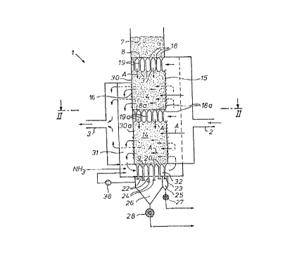
The adsorption reactor 1 illustrated is Figures
1 and 2 inn vertical and horizontal sections has a,raw gas
inlet 2 and a clean gas outlet 3. Between the inlet and
the outlQt, the fluid flows through a first reaction
stage 4 a~d a second reaction stage which is subdivided
into twq reaction chambers 5a and 5b connected in
parallel ~ (Figure 2 ) .
The first reaction stage 4 has a reaction chamber
14 which is rectangular in cross section and, is
operation, is filled with a bed of bulk material consist
ing of as adsorbent in lumps or is granular form. On the
inlet side, the chamber 14 is bounded by a.shutter 15
which extends over the full chamber height and, on the
outlet side, by a shutter 16 which extends only up to a
limited height. The adsorbent is supplied from a feed
container 7, fitted on top of the chamber 14, via a
distributing bottom 8 at the top. In the exemplary
embodiment illustrated, the distributing bottom comprises
a uniform grid of square feeding funnels 18 which are
arranged adjacently and one behind another is rows and
columns and are adjoined by feed pipes 19 opening out
into the chamber 14.
An intermediate bottom Sa is built is about half
way up the chamber 14.~Its.main purpose is to relieve
pressure in high adsorption beds and, in the exemplary
embodiment illustrated, it has the same design and
arrangement (grid of feeding funnels 18a and feed pipes
19a and barrier route 30a) as the distributing bottom 8.
- CA 02196217 2000-03-07
- 20 -
The guiding of fluid through the pile of bulk mate=ial
below the intermediate bottom 8a also-corresponds to that
in the top region. Fitting one or more intermediate
bottoms 8a into the reaction chamber is not essential,
but is often expedient.
Similar to the distributing bottom 8, a discharge
bottom 9 is made up of a grid of discharge funnels 20
arranged adjacently and one behind another. The discharge
funnels 20 are adjoined by discharge pipes 2 2 . The
discharge pipes 21 are closed off by closure elements 23,
e.g. flaps or slides. and the discharge pipes 22 are
closed off by closure elements 24. To discharge the bulk
material from the chamber 14, the closure elements 23, 24
are actuated in a known manner. The discharge pipes open
out into different delivery containers 25 and 26, from
which the adsorbent loaded with the segregated pollutants
can be conveyed away for further processing with the aid
of suitable conveying devices 27, 28 - illustrated here
as a cellular wheel sluice.
The layer of bulk material corresponding to the
inlet-side row of feeding funnels 18 and correspondingly
also of discharge fuxmels 20 is preferably separated from
the rest of the column of bulk material by a partition 17
according to the invention (Figure 3), so that the
adsorption layer 40 between the inlet ahutter~l5 and the
partition l7 can be conveyed away separately via the
associated discharge funnels 20, discharge pipes 21,
delivery containers 25 and conveying device 27.
Naturally,. this applies in a similar way to the adsorp-
21 ~~2~'
WO 96/04065 - 21 - PCT/EP95/02725
tion layer 41 on the downstream side of the partition 17.
The raw gas inlet 2 widens to the overall height
dimension of the reaction chamber 14, specifically up to
the region of the feeding funnels 18 and feed pipes 19.
The fluid can therefore enter the adsorbent bed both from
the side through the shutter 15 and between the feed
pipes 19 from above through the pile 37 of bulk material,
as depicted by the solid arrows A in Figure 1. The fluid
can therefore reach all the zones of the bed of bulk
material, not only in a traveling bed, but also in a
fixed bed. Thus virtually all the particles take part in
the reaction in the same way.
Provided on the outlet side, between the top
layer (pile 37 of bulk material) and the upper end of the
downstream shutter 16 is a barrier route 30 in the form
of a closed wall which prevents any short circuit of the
fluid from above directly into the outlet duct 31. The
outlet duct 31 merges into a horizontal duct section 32
which runs below the discharge bottom 9. The prepurified
fluid leaving the reaction chamber 14 through the outlet
duct 31 flushes the discharge funnels 20 and the dis-
charge pipes 21, 22 in the duct section 32 and, in doing
so, heats the adsorbent located in these elements to the
extent that the risk of condensation is reliably reduced.
The fluid is deflected from the duct section 32 upward
into a fluid inlet region 35a and 35b for the two
chambers 5a and 5b of the second reaction stage (Figure
2). The fluid distribution in the two chambers 5a and 5b
corresponds in principle to the fluid distribution
2196217
WO 96/04065 - 22 - PCT/EP95/02725
described above on the inlet side shutter 15 and the pile
37 of bulk material at the top of the first reaction
stage 4. Feeding and discharge funnels are also arranged
in a grid-like manner in the two chambers 5a and 5b in
order to ensure that the participation of the adsorbent
is as even as possible throughout the interior of the
chambers 5a and 5b. However, the discharge of the loaded
adsorbent generally takes place through all the discharge
funnels and pipes of the second reaction stage 5a and 5b
at the same time. The outlet ducts 36a and 36b also have
a design Which corresponds to the outlet duct 31 in the
region of the downstream shutter of the two reaction
chambers 5a and 5b, thus also ensuring a large-area
transverse flow of the fluid in the chambers 5a and 5b.
The two ducts 36a and 36b join together in the clean gas
outlet 3, as in the illustration in Figure 2.
The two reaction stages 4 and 5 are arranged
adjacently, the second reaction stage being subdivided
into two part-chambers 5a and 5b. This combination
combines the advantages of a compact construction with
good utilization and loading of the adsorbent and simple
control possibilities of the adsorption fronts.
The duct section 32 may possibly also be made to
be so wide that it extends over the full width of the
three adjacently arranged reaction chambers 5a, 14 and 5b
and thus also heats the discharge pipes of the chambers
5a and 5b.
As can be seen in Figures 1 and 3, NH3 as a
reducing agent is injected in at the deflection point
y 2i9~2~7
WO 96/04065 - 23 - PCT/EP95/02725
between the outlet duct 31 and the horizontal duct
section 32. Of course, other feed points or preloading of
the activated hard coal coke in the chambers 5a and 5b
are also possible.
Also with respect to the shapes and dimensions of
the individual funnels 18 and 20, the invention is not
subject to any particular exceptional conditions. The
square cross-sectional shape illustrated or, if
appropriate, a rectangular cross-sectional shape ensures
utilization of the cross-sectional surface over a parti-
cularly large area to distribute the bulk material and a
favorable bulk material mechanism. However, other shapes
are possible with, in principle, the same advantages of
the invention.
Upstream surfaces of different sizes of the two
reactor stages, in particular larger upstream surfaces of
the first stage 4 relative to the second stage 5, are
often expedient in order to achieve a fluid flow speed
which is adapted to the bulk material and the adsorption
characteristics. Specifically to enlarge its upstream
surfaces, the first reactor stage may be subdivided into
two parallel part-chambers instead of the second reactor
stage. Guiding of the fluid is then, of course, in the
opposite direction to that illustrated in Figure 2.
In the feed containers 7 which are separate for
all the chambers 5a, 14 and 5b, there is new bulk
material for the exchange of the exhausted adsorbent. It
is important to keep the loaded adsorbent separate in the
case of the adsorption of highly toxic substances and of
21°~~~~
WO 96/04065 - 24 - PCT/EP95/02725
less aggressive media. In the arrangement described, this
takes place simply due to the fact that layers of adsor-
bent corresponding to different adsorption fronts are
discharged into the separate delivery containers 25 and
26 (or into delivery containers of the chambers 5a and
5b) and are conveyed further from there. These different
adsorption layers 40 and 41 are illustrated in Figure 3.
In the entry-side adsorption layer 40, for example, the
majority of heavy metals, in particular Hg, can be
adsorbed and discharged via the discharge pipes 21 and
the delivery container 25.
However, the exemplary embodiment illustrated in
Figure 3 differs from the exemplary embodiment according
to Figure 1 also by the fact that the distributing bottom
8' is arranged so as to rise from the entry side to the
downstream side of the reactor 1'. This lengthens the
barrier route 30 in an otherwise identical design of the
adsorption reactor 1'. The sectional view according to
Figure 2 also applies to the exemplary embodiment accord-
ing to Figure 3.
However, the raw gas inlet 2 can also extend down
to below the discharge bottom 9. suitable openings to the
interior of the reaction chamber 14 then being formed in
the discharge funnels 20, through which openings raw gas
can enter, but no granular adsorbent can escape into the
fluid entry distributor. Upstream bottoms of this type
are known, for example, from German Utility Model
G 87 06 839.8. If the discharge bottom 9 is designed as
an upstream bottom, a barrier route corresponding to the
2196217
WO 96/04065 - 25 - PCT/EP95/02725
barrier route 30 must also be provided on the rear wall
directly above the bottom 9 in order to avoid fluid short
circuits toward the outlet duct 3l.
A fan 38 is arranged with a connecting line
between the larger delivery container 26 and the duct
section 32 with the purpose of breaking up any caking in
the individual funnels or in the discharge pipes at the
beginning of the adsorbent discharge by means of an
artificially imposed flow by extracting gas.
Figures 4 and 5 illustrate a preferred embodiment
of a two-stage reactor 40' whose main components are
built into a cylindrical reactor housing 41' . Arranged in
the housing 41' are two annular reaction chambers 44 and
45 nested concentrically one inside the other. In the
exemplary embodiment described, the chambers 44 and 45
are filled with different adsorbents, for example the
outer chamber 44 with OHC and the inner chamber 45 with
pelletized activated hard coal coke. Correspondingly, the
outer chamber 44 serves to separate the pollutants which
can be adsorbed more readily (corresponding to the first
stage 4 of the exemplary embodiment described above) and
the inner chamber 45 serves for NOX reduction correspon-
ding to stage 5 of the exemplary embodiment described
above. The first and second chambers 44 and 45 are each
surrounded by annular fluid outlet ducts 46 and 47. A
fluid inlet 48 is likewise designed as an annular duct
and is arranged on the side of the chamber 44 located
radially on the inner side. The fluid inlet 49 of the
second chamber 45 located on the inside is a central duct
21962~~
WO 96/04065 - 26 - PCT/EP95/02725
which runs along the central axis 50 of the reactor 40'.
The annular fluid inlet 48 of the first reaction chamber
44 and the likewise annular fluid outlet 47 of the second
reaction chamber 45 are separated by a partition 51 which
in this case is cylindrical.
In the top region of the reactor housing 41', a
helical entry duct 52 is arranged coaxially around its
central axis 50 and is connected to the annular duct
serving as fluid inlet 48 of the first reaction chamber
44. Owing to the helical arrangement of the entry duct
52, the fluid to be purified and possibly loaded with
solid particles and/or water droplets receives a
relatively strong swirl which forces the heavier par-
ticles and droplets outward into the region above the
piles 37 of bulk material and between the feeding funnels
and feed pipes 18 and 19 of the first reaction stage. The
design and arrangement of the feeding and discharge
funnels and the introduction of the fluid into the two
reaction chambers 44 and 45 correspond to the conditions
explained with reference to Figures 1 to 3. Owing to the
circular arrangement and subdivision of the distributing
bottoms 8 and discharge bottoms 9, however, the funnels
18 and 20 preferably have a trapezoidal design, as can be
seen in Figure 5.
The design of the shutters or other separating
elements to bound the reaction chambers 44 and 45 may
also correspond to those of the exemplary embodiment
described above, the shutters 55 and 56 (or 65 and 66),
however, having an approximately circular annular design
219627
WO 96/04065 - 27 - PCT/EP95/02725
by sufficient segmenting on the upstream and downstream
sides corresponding to the chamber cross section.
As already mentioned, the fluid which has not
been purified enters the reactor housing 41' through the
entry duct 52 which imposes a swirl, it reaches the
mainly cylindrical upstream surfaces in the region of the
shutter 55, crosses the annular first reaction chamber
44, emerges on the downstream side thereof through the
downstream shutter 56 into the outlet duct 46, is
deflected downward into a circular flow chamber 58 where
it flows radially inward in the direction of the central
fluid inlet 49 of the second reaction chamber 45. In the
circular flow chamber 58, the fluid flushes the discharge
funnels 20 and the discharge pipes 22 in a similar way as
in the exemplary embodiment described above.
In the central fluid inlet 49, the fluid which
has been freed from the rapidly adsorbed pollutants, i.e.
has been partially purified, is firstly distributed
axially and flows from there corresponding to the arrows
in a cross-flow or between the feed pipes 19 from above
into the ring of bulk material of the second reaction
chamber 45. The shutter 65 separates the chamber 45 on
the inlet side and the shutter 66 separates the chamber
45 on the outlet side from the adjoining fluid ducts 49
and 47 respectively. The fluid outlet duct 47 opens out
in the top part into a discharge funnel 59 from where the
clean gas can be conducted into a centrally arranged
stack 60.
The upstream surface of the first reaction
WO 96/04065 - 28 - PCT/EP95/02725
chamber 44 corresponding to the shutter 55 is larger, for
example in the ratio of radii, than the upstream surface
of the second reaction chamber 45 corresponding to the
shutter 65. The flow speed of the fluid in the first
chamber 44 is correspondingly slower in comparison to
that in the second chamber 45. This is also desirable, in
particular when different adsorbents are used in the two
chambers 44 and 45.
Annular feed containers 61 and 62 are likewise
arranged above the annular distributing bottoms 8. A
motor-driven distributing device in the form of a
rotating rake 63 is arranged in or above the inner feed
container 62. The rotating rake 63 levels the bulk
material located in the container 62 even in the case of
feed via a single fixed feed nozzle, even if the latter
were to be arranged laterally.
The feed container 61 assigned to the first
reaction chamber 44 is charged with the aid of a rail
trolley 67 through charging openings 68 distributed in a
circle around the central axis 50. The trolley runs on a
ring 69 of rails which is likewise concentric to the
central axis 50. The trolley is preferably provided with
means for airtight docking with the charging openings 68,
a loading space which can be closed in an airtight
manner, and a fan for pressurizing the loading space. In
this design, the overpressure prevailing in the reaction
chamber 44 and thus also in the feed container 61 can be
compensated in the loading space of the trolley 67 , so
that no smoke gas can escape into the trolley and from
WO 96/04065 - 29 - PCT/EP95/02725
there into the ambient atmosphere.
In the embodiment according to Figure 6, the
adsorption reactor has a housing 201 which contains a
reaction chamber 202 for adsorbent, in this case active
coke. The reaction chamber 202 is bounded by shutters
203. Located above the reaction chamber 202 is a feed
container 204 from which the reaction medium passes via
a plurality of feeding funnels 205 into the reaction
chamber. Provided below the reaction chamber is a
delivery container 206 which receives the exhausted
adsorbent. In this case, the latter travels through a
plurality of discharge funnels 207.
The gas to be purified enters the housing 201
through an inlet 208 on the left side. A lower wall 209
prevents the gas from traveling upward directly along the
housing. On the contrary, it is forced to flow around the
discharge funnels 207 and heat the latter, so that no
condensation phenomena can occur there. The gas is then
deflected upward on the right by the reaction chamber 202
and flows through the reaction chamber from right to
left. The space on the right is closed off toward the top
by an upper wall 210. Before the gas can escape through
an outlet 211, it is forced to flow around the feed
container 204 and the feeding funnels 205, specifically
in such a way that the top of the feed container is also
available for heat transfer. The adsorbent is thus
preheated and is already in an active state when it
enters the reaction chamber 202. The feed container 204
is charged with adsorbent via a supply pipe 212. The
~) ~~~
W0 96/04065 - 30 - PCT/EP95/02725
section of the supply pipe 212 located in the housing 1
is also heated. The reaction chamber 202 contains two
diagrammatically indicated partitions 213 and is sub-
divided by the latter into a total of three layers. The
layers permit different guiding of the adsorbent and the
application of different adsorbents.
As can be seen from Figure 6, two reaction
chambers adjoin one another transversely to the through-
flow direction. This is illustrated by a diagrammatically
indicated partition 214. The feed container 204 and the
delivery container 206 are common to both reaction
chambers. Furthermore, a continuous delivery rake 215
which is actuated by a single drive extends over the
entire length of the delivery container 206.
Extending from the feed container 204 to the
upper wall 210 is a barrier wall 216 whose lower edge
defines the center point of an arc 217 of a circle
(Figure 7), the radius of this arc corresponding to the
width of the reaction chamber 202, measured in the
throughflow direction. The feeding funnels 205 lie with
their outlets approximately on this arc in order likewise
to roughly approximate the surface of the adsorbent to
this arc. The gas flowing around the lower edge of the
barrier wall 216 thus has to travel essentially over the
same route up to the surface of the adsorbent as the gas
flowing transversely through the reaction chamber 202.
In Figure 8, identical parts are denoted by
identical reference numerals.
The modular construction according to the inven-
2196217
WO 96/04065 - 31 - PCT/EP95/02725
tion in one direction has already been explained with
reference to Figure 6. According to Figure 8, a total of
four elements are positioned one behind another in this
direction, cf. the three partitions 214 indicated.
. Furthermore,. Figure 8 shows that in each case two
laterally adjacent reaction chambers 202 are combined to
form a module 218, and that the device contains two of
these modules. The inlet 208 supplies a common space
which is located between the discharge bottoms, formed by
the discharge funnels 207, and the delivery containers
206. The lower walls 209 force the gas into the space
between respectively adjacent reaction chambers. The
upper walls 210 are formed here by the feed containers
204, each module 218 having a single feed container for
its two reaction chambers 202. After flowing through the
reaction chambers 202, the gas passes, on the one hand,
into the lateral spaces between the modules 218 and the
housing 201 and, on the other hand, into the central
space between the two modules . Again the two feed con-
tainers 204 lie in a common space which laterally adjoins
the duct-shaped outlet 211. Each module has a single
delivery container 206. The modular construction accord-
ing to the invention allows the block-type construction
of the reactor to be maintained with any desired
extension.
Modifications are quite possible within the scope
of this embodiment. For instance, differing from Figure
8, a single module may be used. It is also possible,
instead of the delivery rake 215, to use a delivery
219b21 ~
WO 96/04065 - 32 - PCT/EP95/02725
device of a different type. The duct-shaped inlets and
outlets 208 and 211 shown in Figure 8 can be replaced by
individual pipes which lead to a common header. Further-
more, it is possible to arrange the inlet 208 likewise on
the end face and the outlet 211 likewise laterally in
Figure 6. The inlets and outlets 208 and 211 can equally
lie on the end face according to Figure 8.
The partitions 213, which are indicated only
diagrammatically here, comprise shutter constructions and
bear, on their upstream side, a slotted hole screen whose
slot bars run vertically. A slotted hole screen of this
type is also arranged on the upstream side of the down-
stream shutter 203.
The partitions 213 may also be replaced by simple
perforated metal plates.
The partitions 214 may be separating walls or
perforated metal plates. They can also be omitted
completely.
Figure 9 shows a diagrammatic vertical section
through a part of an exemplary embodiment of an adsorp-
tion reactor 101. In the exemplary embodiment described,
the reactor 101 has a rectangular cross section. It has
a housing 102 which surrounds a reaction chamber 103.
Provided in the housing 102 are a distributing bottom
with feeding funnels arranged in a matrix-like manner for
the uniform distribution of the bulk material over the
cross section of the chamber 103 and a discharge bottom
106, 106a which has a plurality of discharge funnels for
discharging the bulk material from the chamber 103.
CA 02196217 2000-03-07
33
A partition 107 running essentially vertically
separates the chamber 103 into two adsorption layers 103a
and 103b. The layer 103a faces the entry shutter 109 and
the layer 103b extends from the downstream side of the
partition 107 to the reactor outlet shutter 108 located
opposite.
The fluid to be treated - in the exemplary
embodiment smoke gas - flows through the reactor 101 in the
manner depicted by arrows. The smoke gas enters the reactor
101 at the bottom, flows around the discharge bottom 106
with the discharge funnels and discharge pipes and enters
the upstream adsorption layer 103a through a gas inlet box
and the entry shutter 109 over the majority of the
construction height of the housing 102. In the exemplary
embodiment described, the angle of incidence of the louvers
forming the shutter 109 is 70° ~ 5° relative to the
horizontal plane. The fluid flows through the bed in the
layer in the transverse direction, as shown by the flow
lines. The fluid emerges on the downstream side through the
outlet shutter 108 and its louvers 110 into a gas outlet
box. The wall construction on the outlet side has the
louvers 110 which are arranged vertically one above another
and, in the exemplary embodiment described, are set at an
angle of 60° ~ 5°, preferably 60° to 65°, relative
to the
horizontal plane.
The new aspects according to the invention relate
above all to the design of the partition 107 which, in the
exemplary embodiment described, runs vertically and
2196211
WO 96/04065 - 34 - PCT/EP95/02725
to the shutter 108, of quite similar design, of the
reactor housing 102. These new aspects are to be
explained in greater detail below with reference to the
diagrammatic partial views according to Figures 10 to 12.
As shown above all in the enlarged horizontal
sectional view according to Figure 10, the partition 107
and the shutter 108 are designed as a slotted bottom. The
latter comprises an upstream slotted hole screen 113 with
bar-shaped slot-bounding elements 113a running from the
top to the bottom and of uniform triangular cross
section. The slotted hole screen 113 is connected in a
sandwich-like manner to a stabilizing grid 114. In the
case of a customary grain size of the activated coke used
as adsorbent, the slot-bounding elements 113a have a slot
width of 1.25 mm t 0.5 mm, a profile side length facing
the activated coke bed of 2.2 mm t 0.5 mm, and a depth to
the stabilizing grid of 4.5 mm t 1 mm. However, these
dimensions correspond only to an exemplary embodiment
implemented in a prototype; in particular the width of
the slot 113b between two adjacent slot-bounding elements
113a is expediently oriented by the size of the bulk
material particles which are to be retained by the
slotted hole screen in the entry-side adsorption layer
103a (or in the case of the shutter 108 in the outlet-
side adsorption layer 103b).
According to Figure 10, the stabilizing grid 114
comprises connecting bars 115, which run transversely to
the slot-bounding elements 113a, and web profiles 116
arranged at greater intervals parallel to the slot-
2196217
WO 96./04065 - 35 - PCT/EP95/02725
bounding elements. The longitudinally running bar-shaped
slot-bounding elements 113a are spot-welded to the
connecting bars 115 arranged at greater intervals one
above another; on the other side, the web profiles 116
are welded to the transversely running connecting bars
115. The narrow sides remote from the connecting bars 115
can alternatively be connected, in particular welded, to
twisted square bars 118 in the manner illustrated in
Figure 10. These square bars are commercially available
as an assembly unit with the web profiles 116 (for other
purposes) and are therefore also used here. The square
bars 118 can also be provided instead of the rectangular
or round connecting bars 115.
As mentioned above, the outlet shutter 108 of the
reaction chamber 103 is provided, in the exemplary
embodiment described, with the same approximately ver-
tically running slotted bottom 112 as the partition 107.
The bulk material is thus retained on the upstream side
of the slotted bottoms 112 both of the partition 107 and
of the shutter 108, at least to the extent that its
particle diameter is larger than the slot width 113b of
the slotted hole screen 113. Insofar as small-grain
particles can penetrate the slots 113b in the fluid
throughflow direction (arrow A in Figure 10), they arrive
at vertical ducts 117 formed between the flat sides of
the profiles 116 and drop through these (continuous)
ducts down into a delivery region which is denoted by 119
in Figure 12 for the outlet shutter. In the delivery
region, these fine-grain particles are either fed back to
2196217
WO 96/04065 - 36 - PCT/EP95/02725
the adjacent discharge funnel of the discharge bottom 106
or else, if appropriate, conducted away separately in
order to continuously reduce the technologically unfavor-
able dust components.
Other than with conventional transverse flow
adsorbers, no noticeable accumulations of bulk material
form on the obliquely arranged louvers 110 on the outlet
side of the housing 102, so that the fluid is subject to
a uniform flow resistance on the downstream side over the
entire height of the housing. The angle of inclination of
the individual louvers 110 of the shutter is thus also
uncritical; however, the angle of inclination is prefer-
ably sufficiently large to feed any bulk material
impinging on the louvers 110 back into the ducts 117 or
to allow it to flow away. For this purpose, an angle of
about 60° t 5° relative to the horizontal plane has
proved to be expedient for the louvers 110.
The partition 107 has a different arrangement of
the shutter louvers 120 on the downstream side facing the
adsorption layer 103b with an otherwise matching design
of the slotted bottoms of the partition 107 and the
shutter 108. The louvers 120 are arranged obliquely
downward from the slotted bottom 112 arid inclined in the
direction of the layer 103b. An angle of inclination of
20° t 5° relative to the vertical plane has proved to be
favorable to ensure, on the one hand, a relatively free
passage of fluid and, on the other hand, to reliably
prevent bulk material passing from the layer 103b into
the entry-side layer 103a. With the acute angle relative
2196217
WO 96/04065 - 37 - PCT/EP95/02725
to the vertical plane, the space requirement of the wall
107 including the louvers 120 in the reactor is also
acceptably small.
As can be seen, the columns of bulk material in
the layers 103a and 103b separated from one another by
the wall 107 are continuously separated from one another
right into the discharge region assigned individually to
them in each case. In particular, the entry-side layer
103a has its own discharge funnels 106a. The larger
particles emerging from the layer 103a through the slot-
bounding elements 113a drop, upon entry into the space
between the web profiles 116, vertically downward through
the ducts 117 and are conducted away by the wall 119'
into the discharge funnel 106a. These loaded particles
are prevented from passing into the layer 103b. The
column of adsorbent located in the relatively narrow
layer 103a can be emptied via the discharge funnel 106a
independently of the main bed of the layer 103b and
passed on for suitable disposal, for example as special
waste material of an incineration plant. Experience shows
that virtually all the highly toxic portions, such as
dioxins and furans, are separated by adsorption in this
relatively thin layer. After passage through the par-
tition 107, the other pollutants are separated by
adsorption in the subsequent layer 103b near to the
outlet over a path length of the fluid which is, for
example, 9 times longer. The disposal of the used or
loaded adsorbent from the layer 103b can be carried out
in a comparatively simple and unproblematic manner. This
2196217
WO 96/04065 - 38 - PCT/EP95/02725
adsorbent can also be regenerated, if appropriate, and
fed back into the reactor 101.
A continuous design both of the slot-bounding
elements 113a and of the web profiles 116 running
parallel to the latter (at a far greater distance) is
generally to be given preference for cost reasons. On the
other hand, these vertically running components 113a and
116 can, however, also be joined together from a
plurality of parts either in an abutting or meshing or
overlapping manner. In particular for the web profiles
116, it is sufficient for these to extend over a partial
length of the reactor height in such a way that the
louvers 110 of the shutter can be attached, in particular
welded, to them. Any interruption in the web profiles 116
is insignificant for the reliable discharge of the small-
grain particles through the ducts 117 since particle
exchange between adjacent ducts 117 does not impair the
guiding of the particles from the top to the bottom, and
the inclined louvers 110 also have a directing effect
obliquely downward.
Figures l3 and 14 show embodiments of slotted
bottoms 140 and 150 respectively, in which the slotted
hole screen comprises in each case a plurality of ver-
tical sections 141a, 141b and 151a...151c respectively
which are arranged in an overlapping manner. In the
embodiment according to Figure 13, each section of the
slotted hole screen is bent twice at its upper end 142
and engages behind the lower end of the higher section
141a of the slotted hole screen. The individual slot-
2196211
WO 96/04065 - 39 - PCT/EP95/02725
bounding bars are aligned vertically with one another in
the overlapping sections 141a and 141b of the slotted
hole screen. Also provided in the modified embodiment
according to Figure 13 is a stabilizing grid 144 with
transversely running connecting bars 145 and with web
profiles 146 bounding discharge ducts 117. However, the
web profiles 146 are interrupted vertically and only
assigned to the flat parts of the sections 141a and 141b
of the slotted hole screen. The shutter louvers connected
to the web profiles 146 are not illustrated in Figures 13
and 14.
In the embodiment in Figure 13, the vertical
boundary plane of the bed of bulk material is interrupted
in the overlapping region of the sections 141a and 141b
of the slotted hole screen. A small accumulation 147
forms there. Owing to the free space in the region of the
overlapping point on the other side of the accumulation
147, the increase in the flow resistance there is not
significant. The interruption of the slot-bounding
elements or of the slots 113b formed between the latter
has the advantage, however, that particles, in particular
elongate particles, of bulk material trapped in slots
113b can be freed from the slot guide in sections, namely
in the region of the accumulation 147, and can reorient
themselves.
A similar effect is achieved in the modified
embodiment illustrated in Figure 14. The active slot-
bounding elements in the sections 151a to 151c of the
slotted hole screen run predominantly at a slight
2i 921 l
WO 96/04065 - 40 - PCT/EP95/02725
inclination to the generally vertical direction of travel
of the bulk material in the reaction chamber 103. Owing
to the inclination of the sections of the slotted hole
screen, only one bend is provided in the overlapping
region 152 in the embodiment according to Figure 14.
In the embodiment according to Figure 14, too, a
stabilizing grid is assigned individually in each case to
the sections 151a...151c of the slotted hole screen. Only
the transversely running connecting bars 155 are illus-
trated in Figure 14.
Numerous modifications are possible within the
scope of the concept of the invention. For instance, the
individual components belonging to the slotted bottom 112
may predominantly have rounded edges and, taking account
of the stabilizing requirements, large intervals and/or
small wall thicknesses. The downstream side may, if
appropriate, also be curved horizontally or be designed
to be polygonal and flat in sections. The design of the
shutter is uncritical owing to the particular supporting
and holding function of the slotted bottom 112, 140 or
150. The size of the ducts should be chosen to ensure,
wherever possible, that, on the one hand, the space
requirement is small arid, on the other hand, that the
particles of bulk material passing through the slotted
hole screen are reliably conducted away under the
influence of gravity.
Furthermore, it is readily possible within the
scope of the invention to use only a single adsorption
layer. The flow direction of the fluid can also be
21~62i1
WO 96/04065 - 41 - PCT/EP95/02725
reversed; for example in Figure l, so that the raw gas
enters the adsorber 1 at 3 and leaves the latter at 2.
The raw gas then emerges from the adsorption layer at the
top.