Note: Descriptions are shown in the official language in which they were submitted.
CA 02196424 1997-O1-30
WO 96/04125 PCTIIIS95/09106
Description
Method and Apparatus far Forming
Airfoil Structures
Technical Field
This invention relates to a method and apparatus for
assembly bonding of an airfoil structure, such as a heli-
copter rotor blade.
Background Art
Modern day airfoil assemblies such as helicopter
rotor blades, flaps, ailerons, and the like, include
internal components such as structural support components
such as a rotor blade spar; airfoil-shaping honeycomb
components; and the like. These airfoil assemblies in-
clude an external skin which forms an envelope for the
airfoil, and is typically made of several plies of fiber-
glass or graphite impregnated with a resin matrix gener-
ally epoxy, which is referred to in the industry as "pre-
preg". The internal airfoil components are preassembled
and then are positioned in a molding assembly which _
serves to locate and bond the external skin to the inter-
nal components of the airfoil. The molding assembly
includes cooperating mold halves, which comprise a steel
base mold member which has an internal cavity that con-
forms to the desired configuration of the upper or lower
surface of the airfoil; and a complementary caul plate
member which has an internal cavity that conforms to the
desired configuration of the lower or upper surface of
-1 -
S-4563 CA 02196424 1997-O1-30
219b~~~~,.
the airfoil. The steel mold is used for the most contour critical airfoil
which is
usually the upper airfoil.
Recent developments in forming composite articles such as helicopter
components describe the use of molding assemblies with various configurations,
S which molding assemblies include a rigid mold member typically formed from
steel, and a mating caul plate member which is compliant so as to improve the
molding operation. U.S. Patent Nos. 5,071,333, granted December 10, 1991 to
A.C. Dublinski, et al., 5,087,187, granted February 11, 1992 to R.J. Simkulak,
et
al., and 5,152,949, granted October 6, 1992 to P.B. Leoni, et at., all
describe
methods and tools for forming molded composite articles by the use of a mold
assembly having a rigid mold member and a complementary compliant caul plate
member. The compliant caul plate member is suggested for use in forming
complex details in the article being manufactured (the 5,071,338 patent); and
also
for use in improving the ease of stripping the mold components away from the
IS molded article after the curing of the latter (the 5,152,949 patent). 'The
molded
articles described in each of the aforesaid patents are components of
aircraft.
It is also known in the art to use molding assemblies that include an
inflatable tool for applying bonding pressures of differing magnitude to
adjacent
surfaces of a workpiece. U.S. Patent No. 3,305,420 describes one such
inflatable
tool that comprises a large, flat, dilatable pressure bag formed from layers
of
reinforced ply laminates of glass fiber fabric, impregnated and coated with
rubber
or vulcanized material, and one or more small dilatable pressure bags of
similar
construction disposed in the hollow pressure cavity of the large dilatable
pressure
bag. The hollow pressure cavities of the small dilatable pressure bags are
2S supplied with high pressure air while the hollow pressure cavity of the
large
dilatable pressure bag is supplied with low pressure air.
Disclosure of the Invention
This invention relates to the use of a molding assembly for use in
assembling the external skin of an airfoil for a helicopter, or the like, such
as the
rotor blade of a helicopter, and the internal structural components of the
airfoil.
The molding assembly of this invention includes a rigid mold body, preferably
formed from steel, which has an inner surface that defines the shape of the
upper
surface of the airfoil. The molding assembly also includes a complimentary
caul
plate which has an inner surface that defines the shape of the lower surface
of the
3S airfoil. The caul plate has a forward edge section thereof which is
essentially rigid
throughout the length of the caul; and an opposite. aft edge section
2
. , , .w~ gHEET
;:.:: . . . - ,6 ~ ~~IEP
CA 02196424 1997-O1-30
WO 96/04125 ~ ~ ~ ~ rl' ? ~ PCT/US95109106
which is essentially compliant. The caul plate also
includes an intermediate section which has a declining
rigidity and which interconnects the forward edge section
and the aft edge section of the caul.
The essentially rigid forward edge section of the
Gaul plate provides the capability of creating a precise
airfoil surface by forcing the leading edge of the air-
foil to conform to a predefined and relatively precise
shape around the airfoil spar and other internal compo-
l0 nents. At the same time, the compliant aft edge section
of the Gaul plate is forgiving of dimensional variations,
all of which are within tolerance, which are associated
with the machining of the honeycomb core portion aft of
the spar, while maintaining a uniform pressure across the
trailing portion of the airfoil.
The caul plate is preferably laminated from layers
of preimpregnated fiberglass or graphite composite cloth.
The cloth layers are preimpregnated with a resin such as
epoxy that can withstand curing temperatures and are
bonded to each other in layers to form the caul. The
rigid forward edge portion of the caul plate will prefer-
ably include a greater number of prepreg composite sheet
components than the compliant aft edge section thereof to
provide the requisite stiffness requirements of each
section of the caul plate. The relative stiffness and
compliance of the edge sections of the caul plate are
directly related to the stiffness of the fiberglass skin
being applied to and bonded to the airfoil structure.
The compliant edge section of the Gaul plate is prefers-
bly about 6 times more stiff than the airfoil skin. The
rigid end section of the caul plate should be at least
twice as stiff as the compliant edge section.
It is therefore an object of this invention to pro
vide a method and apparatus for assembly bonding an air
foil structure with a leading edge molded to a precise
airfoil shape and a trailing edge compliantly bonded to a
honeycomb core. The leading edge section internal compo-
_3 _
CA 02196424 2005-07-27
nents allow adjustment to the precise shape through variable adhesive
thickness. The
trailing edge shape is compliant to the core contour with a uniform adhesive
thickness.
It is a further object of this invention to provide a method and apparatus
of the character described wherein the leading edge of the skin on the airfoil
component
is rigidly confined to the remainder of the airfoil to provide a precise
leading edge
shape for the airfoil.
It is an additional object of this invention to provide a method and
apparatus of the character described wherein the trailing edge of the skin on
the airfoil
is compliantly applied to the core with a uniform pressure across the trailing
edge of the
airfoil.
It is another object of this invention to provide a method and apparatus
of the character described wherein degree of confinement of the skin to the
remainder
of the airfoil at the leading and trailing edge is directly related to the
stiffness of the
airfoil skin and the internal structure.
Therefore, in accordance with the present invention, there is provided a
method of applying an outer skin layer to an airfoil having a chord line, a
pitch axis, a
leading edge section, and a trailing edge section, said method comprising the
steps of
providing a molding assembly that includes a rigid body member and means for
cooperating with said rigid mold body to confine the airfoil when the outer
skin layer is
applied to the airfoil, laying up internal airfoil components and the outer
skin layer in
the molding assembly, and applying pressure over said cooperating means of the
molding assembly to form the airfoil, characterized in that said providing
step
comprises providing a caul plate having a stiffened forward edge section and a
compliant aft edge section as said cooperating means of said molding assembly,
said
pressure applied over said stiffened forward edge section of said caul plate
provides the
outer skin layer with a highly controlled curvature over the leading edge
section of the
airfoil, and said pressure applied over said compliant aft edge section of
said caul plate
causes the outer skin layer to smoothly conform to the trailing edge section
of the
airfoil despite dimensional variations of the internal airfoil components.
Also in accordance with the present invention, there is provided a
molding assembly for applying an outer skin layer to an airfoil having a chord
line, a
pitch axis, a leading edge section, and a trailing edge section, said molding
assembly
comprising a rigid mold body having an inner surface that defines one surface
configuration of the airfoil, and means for cooperating with said rigid mold
body to
confine the airfoil when the skin layer is applied to the airfoil, said means
having an
inner surface that defines the other surface configuration of the airfoil,
characterized in
that said means is a caul plate having a stiffened forward edge section that
confines one
-4-
CA 02196424 2005-07-27
side of the leading edge section of the airfoil and a compliant aft edge
section that
confines one side of the trailing edge section of the airfoil when said skin
layer is
applied to the airfoil.
Further in accordance with the present invention, there is provided a caul
S plate for use in a molding assembly for applying an outer skin layer to an
airfoil having
a chord line, a pitch axis, a leading edge section, and a trailing edge
section, said caul
plate comprising a plurality of overlain plies of preimpregnated composite,
characterized by a stiffened forward edge section that contours one side of
the leading
edge section of the airfoil when the skin layer is applied to the airfoil, and
a compliant
aft edge section that confines one side of the trailing edge section of the
airfoil when
the skin layer is applied to the airfoil.
These and other objects of the invention will become more readily
apparent from the following detailed disclosure of an embodiment of the
invention
when taken in conjunction with the accompanying drawings, in which:
BRIEF DESCRIPTION OF THE DRAWINGS
FIG. 1 is a schematic sectional view of an airfoil assembly which
includes an external skin applied to an internal airfoil structure;
FIG. 2 is a schematic sectional view of an apparatus formed in
accordance with the invention; and
FIG. 3 is a top plan view of the apparatus of FIG. 2.
-4a-
CA 02196424 1997-O1-30
WO 96/04125 L PCT/US95/09106
Best Mode For Carrying Out The Invention
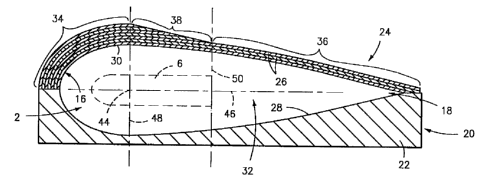
Referring now to the drawings, there is shown in
FIG. 1 a typical helicopter rotor blade airfoil struc-
ture, which is denoted generally by the numeral 2. The
rotor blade 2 has an internal structure denoted generally
by the numeral 4 which includes a spar 6 which is a pri-
mary support member, and which is typically formed from
metal or composite material; a honeycomb core part 8; and
may also include tuning weights, a deicing system, etc.
(not shown in detail). The rotor blade 2 has an outer
skin of fiberglass prepreg 10 which for purposes of il-
lustration is shown as a bilayer skin having two superim-
posed fiberglass sheet components 12 and 14. The leading
edge of the rotor blade 2 is denoted generally by the
numeral 16 and the trailing edge is denoted generally by
the numeral 18.
Referring now to FIGS. 2 and 3, a somewhat schematic
view of the molding assembly of this invention used to
apply the skin 1o to the internal components 4 of the
rotor blade 2 is shown, which molding assembly is denoted
generally by the numeral 20. The molding assembly 20
includes two components, one of which is a rigid mold
body 22 preferably formed from steel; and the other of
which is a caul plate 24 which is preferably formed from
superimposed layers of preimpregnated fiberglass sheets
26. The internal surfaces 28 and 30 of the mold body 22
and caul plate 24 are configured in conformance with the
desired shape of the outer surface of the rotor blade
skin. It will be understood that the rotor blade fiber-
glass skin sheets are applied to the internal blade com-
ponents so as to cover the latter, and the composite
assembly is positioned in the mold cavity. Either a
vacuum or positive pressure is applied over the caul
plate. Adhesives used are generally elevated temperature
curing. The position of the blade spar is denoted by the
numeral 6 and is shown in phantom.
-5 -
CA 02196424 1997-O1-30
WO 96/04125 PCTIUS95/09106
?~ 9c~~ %~
The caul plate 24 is formed from a plurality of
fiberglass or graphite prepreg sheets 26, and includes a
thick forward edge section 34 which overlies the leading
edge portion 16 of the rotor blade assembly 2; a rela-
y tively thin aft edge section 36 which overlies the trail-
ing edge portion 18 of the rotor blade; and an intermedi-
ate section 38 wherein the thickness of the caul plate 24
gradually declines from the leading edge 16 to the trail-
ing edge 18 of the rotor blade 2. The preferred way of
forming the thicker and thinner caul plate edge sections
34 and 36 is by gradually reducing the number of compos-
ite plies 26 which make up the caul plate 24 through the
intermediate section 38 of the caul. Thus the number of
composite plies 26 which make up the caul plate section
34 could, for example, be seven; and the number of com-
posite plies 26 which make up the caul plate section 36
could, for example, be three. The number of composite
plies which make up each section of the caul plate 24
will be determined by the target stiffness of the fiber-
glass skin to on the rotor blade 2, as clarified herein.
The boundaries of the caul plate sections 34, 38 and
36 are determined as follows. The location of the air-
foil spar 6 within the molding cavity 32 governs the
boundaries of the Gaul plate sections 34, 36 and 38. The
spar 6 encapsulates and defines the blade pitch axis 44
which corresponds to the feathering axis of the blade 2.
A line 46 which extends through the pitch axis 44 and the
trailing end 18 of the blade 2, and essentially bisects
the leading edge I6 of the blade is termed the "chord .
line". A line 48 which is perpendicular to the chord
line 46 and extends through the pitch axis 44 defines on
the outer surface of the caul plate 24 one end of the
thick edge section 34 of the caul plate 24, and the be-
ginning of the intermediate section 38 of the caul plate
24 where the thickness of the caul plate tapers off. A
line 50 which is parallel to the line 48 and is tangent
to the trailing edge of the spar 6 defines the end of the
_6 _
CA 02196424 1997-O1-30
WO 96/04125 ~ PGTNS95/09106
intermediate section 38 on the outer surface of the caul
plate 24, and the beginning of the thin compliant caul
plate section 36, which extends to the trailing edge of
the caul. By providing the caul plate 24 with a stiff,
essentially rigid section 34 whose surface 30 defines the
configuration of the leading edge 16 of the rotor blade
2, the portion of the outer skin 10 underlying the Gaul
plate section 34 will form a relatively precise and well
controlled predefined shape on the leading edge portion
of the rotor blade 2. At the same time, by providing the
Gaul plate 24 with a flexible and compliant trailing
section 36, the portion of the outer skin l0 underlying
the caul plate section 36 will be flexibly applied to the
inner trailing edge blade components in a manner that is
tolerant of dimensional variations while maintaining a
uniform pressure across the trailing portion of the blade
outer skin. These forming conditions will be found from
the root end to the tip end of the blade 2 due to the
fact that the caul plate sections 34 and 36 extend for
the full width W of the caul plate 24, as shown in FIG.
3. The resulting blade will thus have an outer skin
which is substantially uniform in each edge section from
the root to the tip of the blade,
It will be readily appreciated that the forming
assembly and process of this invention will provide an
airfoil which has a tightly controlled leading edge sec-
tion shape while at the same time allowing for internal
component dimensional variations in the trailing edge
section of the airfoil. The airfoil-forming mold assem-
bly includes a caul plate member which has an essentially
rigid leading edge section and a compliant trailing edge
section which provides the desired control and flexibili~
ty during the forming of the airfoil. The degree of caul
plate stiffness and compliance is directly related to the
desired stiffness of the skin being applied in the air-
foil.
CA 02196424 1997-O1-30
. ;-4563 L ~ ~ ~'4 ~ ~ ~ ..
..
'.. ..
In view of the fact that variations and changes may be made to the
disclosed embodiment without departing from invention as described herein, the
disclosure of the invention set forth herein is not intended to Iimit the
invention
otherwise than as required by the appended claims.
What is claimed is:
8
,, ,J SHEET
.: MCP
:.; ~:
w
,.