Note: Descriptions are shown in the official language in which they were submitted.
VJO 96107295 PCT/US95110868
APPARATUS AND MET80D FOR MAGNETICALLY
CONTROLLING A HEARING AID
8ACKGROUND OF T8E INVENTION
The present invention relates to hearing aids. More
particularly, the invention relates to remote controlled
hearing aids.
Hearing aids often offer adjustable operational
parameters to facilitate maximum hearing capability and
comfort to the users. Some parameters, such as volume or
tone, may be conveniently user adjustable. Other
parameters, such as filtering parameters, and automatic
gain control (AGC) parameters are typically adjusted by
the acoustician.
With regard to user adjustable parameters, it is
awkward or difficult to remove the hearing aid for
adjustment especially for individuals with impaired manual
dexterity. Remotely controlled units may be utilized to
adjust such desired functions inconspicuously and without
removal of the hearing aid.
Various means have been utilized for the remote
control of hearing aids. A remote actuator of some type
is necessarily required for all remote controlled systems.
Control signals from the remote actuator have been by way
of several different types of media such as infrared
radiation, ultrasonic signals, radio frequency signals,
and acoustical signals.
Often times different listening situations will
warrant different settings of various adjustable
parameters for optimal hearing and comfort. This need may
be addressed by preprogramming various groups of settings
(programs) of the parameters into the memories of the
CA 02196591 2006-02-07
hearing aids. When entering a different environment the user can select the
most suitable group of settings of the adjustable parameters. The remote
control selection of such programs has heretofore required transmission of
coded or modulated signals to activate selection of the desired programs.
Thus necessitating an electrically complex remote actuator and receiver
circuitry in the hearing aid. Obviously, where a remote actuator is inoperable
or unavailable, selection of different programs would be impossible.
Remote actuators used to control parameters and select
programs can have complicated controls which can make them difficult to
understand and use by many hearing aid users. Moreover, users with limited
manual dexterity due to arthritis, injuries, or other debilitating illnesses,
may
find it difficult or impossible to operate remote controls with several push-
button controls. Thus, there is a need for a simple to use remote controlled
hearing aid requiring very limited manual dexterity and in which a number of
hearing aid parameters may be controlled, either individually or by way of
program selections.
As hearing aids have become more sophisticated they have also
become smaller. "Completely in the canal" (CIC) hearing aids are currently
available which are miniaturized sufficiently to fit far enough into the ear
canal
to be out of view. Such placement makes the hearing aid difficult to access
with tools for adjusting the operational parameters. Moreover, such placement
makes remote control where direct access is needed, such as infrared
radiation, difficult or impossible.
In such state of the art hearing aids there is minimal faceplate
space for sensors or controls such as
-2-
WO 96107295 PCf/US95I10868
9 't
potentiometers. Thus there is a need for a means of
controlling adjustable operational parametera'in state of -
the art miniaturized hearing aid without controls or
sensors that take up faceplate space.
SUMMARY OF THE INVENTION
An apparatus and method for controlling one or a
plurality of adjustable operational parameters of a
hearing aid by the movement of an external magnetic
actuator into and out of-proximity with the hearing aid.
The external actuator is hand held and comprises a
magnetic source such as a permanent magnet. The hearing
aid has a microphone for generating signals, hearing aid
circuitry for processing the signals, an output transducer
for transforming the processed signals to a user
compatible form, and a magnetic switch, such as a reed
switch, connected to the hearing aid circuitry. In one
embodiment hearing aid circuitry has a plurality of
adjustable operational parameters and includes control
processing circuity for switching between and controlling
the adjustable operational parameters. The magnetic
source is moved into and out of proximity with the hearing
aid a selected number of times activating or switching -
"on" the magnetic switch each time. The control
processing~circuitry is configured to switch between the
adjustable operational parameters on sequential
activations of the magnetic switch for selection of an
operational parameter to adjust. The control processing
circuity is further configured to adjust the selected
adjustable operational parameter after the activation of
the magnetic switch is maintained a predetermined amount
of time and to stop the adjustment when the magnetic
switch is deactivated.
- 3 -
R'O 96107295 PCfICTS95110868
96591 1
Inone embodiment, ~rious sets of specific settings
of the adjustable parameters may be programmed into a
memory contained in the hearing aid circuitry in the form
of a plurality of programs. The various programs may be
selected by rotating through the programs by sequentially
activating the magnetic switch by moving the actuator into
and out of proximity with the hearing aid.
In a second embodiment the device operates by moving
a magnetic source into proximity with the hearing aid
which closes the magnetic switch and activates the control
processing circuitry to start adjusting the operational
parameter.. The control processing circuitry is configured
to cycle the operational parameter at a predetermined rate
through the range of available settings while the magnetic
source is maintained in said proximity. When the
adjustable parameter is at the desired adjustment
position, the magnetic source is moved out of proximity
which stops the adjustment of the operational parameter.
The control circuitry may include a memory circuit to
allow a desired setting of the adjustable operational
parameter to be saved when the hearing aid is turned off.
Moreover, a trimmer may be provided to adjust the
adjustable operational parameter to a desired setting upon
turning the device on.
A feature of the invention is that the adjustment of
the operational parameter may be simply and
inconspicuously accomplished by minimal movement and
motion. The magnetic actuator is simply moved into
proximity withthe hearing aid for an amount of time as
necessary to adjust the parameter, such as volume, to the
desired setting and is then moved away. The user may
cycle through the entire range of parameter settings
without moving the actuator away from the hearing aid.
- 4 -
2
WO96107295 PCT/US9S110868
A feature of- the invention is that the circuitry
required in the hearing aid is quite limited in comparison
to alternative remote control devices. The invention-
utilizes a single logic level input, that is, a single
on/off switch as compared to modulated infrared radiation
and RF signals that require detection, amplification, and
decoding. Moreover, the device utilizes a single magnetic
switch as opposed to multiple magnetic switches.
A feature of the invention is that the magnetic
actuator utilizes no electrical circuitry, no electrical
components, no batteries, and no moving parts. As a
result, the magnetic actuator offers a very high level of
reliability, is very durable, has a very long service
life, and is essentially maintenance free.
A further object and advantage of the invention is
that the remote actuator is small and inconspicuous, and
may be easily carried in a pocket.
A further object and advantage of the invention is
that if the remote actuator is unavailable, substitute
magnets may be utilized for adjusting the device.
A further object and advantage of the invention is
that the system is essentially immune from sources of
interference which can create difficulties for systems
utilizing RF, infrared, or ultrasonic remote control.
An additional object and advantage of the invention
is that the device needs a minimal amount of manual
dexterity to adjust the operational parameters. The
actuator only needs to be moved into proximity with the _
reed switch and maintained within said proximity to adjust
the operational parameters.
- 5 -
PCTIUS95110868
W O 96/07295
An additional object and advantage of the invention
is that the device need not be removed from the ear for
the adjustment of the adjustable operational parameters.
Moreover, no adjustment tools need be inserted into the
ear for the said adjustment. Nor does the device need to
be visually or physically accessible to adjust the
parameters. .
An additional object and advantage of the invention
is that control of operational parameters in the hearing
aid is accomplished without the use of conventional
potentiometers and switches.
An additional object and advantage of the invention
is that a wide variety of operational parameters may be
controlled by the external magnetic actuator.
RRTFF DESCRIPTION OF THE DRA6VINGS
FIG. 1 is a partial sectional view showing a
completely in the canal (CIC) hearing aid system in place
which incorporates the invention.
FIG. 2 is a partial sectional view showing one
embodiment of a CIC hearing aid incorporating the
invention.
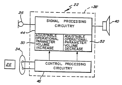
FIG. 3 shows a block diagram ofone embodiment of the
invention.
FIG. 4 shows a block diagram of a modern hearing aid
with available adjustable operational parameters.
FIG. 5 shows a schematic diagram of the embodiment of
the invention shown in FIG 3.
- 6 -
219~~~~
WO 96107295 PCTlUS95/10868
FIG. 6 shows a block diagram of an additional -
embodiment of the invention.
FIG. 7 is a schematic of an example of control
processing circuitry that provides for continued cycling
between maximum and minimum settings of an adjustable
operational parameter.
FIG. 8 is a schematic of-an example of control
processing circuitry for adjustment of an intitial setting
when the hearing aid is turned on.
FIG. 9 is a schematic of an example of control
processing circuitry in which the last setting of the
adjustable parameter is saved when the hearing aid is
tuned off.
DETAILED DESCRIPTION OF TAE PREFERRED EMBODIMENTS
Referring to FIG. 1, a preferred embodiment of the
invention is depicted. The invention is a hearing aid
system which principally comprises a hearing aid 22 which
is shown in place in an ear canal 24 and a magnetic
actuator 26 shown in an actuating position at the ear
pinna 28. As described below the hearing aid 22 has a
plurality of adjustable operating parameters. The
magnetic actuator 26 includes a magnet portion 30. The
hearing aid as depicted is configured as a "completely in
the canal" (CIC) type. The invention may also be embodied
in the other convention configurations of hearing aids
such as "in the ear", "in the canal°, "behind the ear",
the eyeglass type, body worn aids, and surgically
implanted hearing aids. Due to the extreme
miniaturization of CIC hearing aids, the features of the
invention are particularly advantageous in this type of
aid.
WO 96107295 PCT/US95110868
2195591
FIG. 2 shows a cross sectional view of the CIC
hearing aid 22. The hearing aid 22 includes a housing 32,
a magnetic switch shown as a reed switch 34, a microphone
36, hearing aid circuitry 38, a battery 39 and a receiver
40.
FIG. 3 shows a block diagram of one embodiment of the
invention. In this embodiment the remote actuator
controls volume -increase and volume decrease. The hearing
aid circuitry 38 comprises signal processing circuitry 44
and control processing circuitry 46. The signal
processing circuitry 44 receives electrical signals
generated by the microphone 36 and processes the signals
as desired. Such processing would typically include
amplification, filtering, and limiting. The processed
signals are transmitted to the receiver 40. The signal
processing includes a plurality of adjustable parameters
50, 52 identified in this embodiment as volume increase
and volume decrease. The control processing circuitry 46
is connected to the magnetic switch 34 and translates
actuations of the magnetic switch into control signals to
adjust the adjustable operational parameters volume
increase 5D and volume decrease 52. The control
processing circuitry 46 is configured to switch between
and adjust the operational parameters 50, 52 based upon
the actuation of the magnetic switch and the maintenance
of the actuation. This is accomplished by movement of the
magnetic actuator into proximity of the hearing aid and
holding the actuator in said proximity. A suitable
circuit corresponding to the block diagram of FIG. 3 is
shown in FIG. 5-and discussed below.
The embodiment of FIG. 3 utilizes volume increase 50
and volume decrease 52 as the adjustable operational
parameters. In other configurations, volume could be a
single operational parameter. Where used-herein, volume
-a-
296591
W O 96107295 PGT/US95I10868
,Fy ,
and gain are synonymous. Numerous other adjustable
operational parameters are-available to control.
FIG. 4 exemplifies the adjustable operational
parameters that are available in a modern hearing aid.
FIG. 4 is a block diagram of the signal processing
. circuitry 44 which includes a number of circuit segments
providing operational functions with associated adjustable
operational parameters. It is not anticipated that all of -
the operational parameters shown in FIG. 4 would be
adjustable in any particular hearing aid. Suitably, a
select number of operational parameters would be selected
for adjustment capabilities in a hearing aid. The signal
from the microphone 36 goes to a preamp 56 in which the
gain 58 is available as an adjustable parameter. The
signal then goes to an input automatic gain control (AGC)
60 in which the threshold 62 and the AGC ratio 64 are
available as adjustable parameters. The output from the
AGC is split into two channels, a high channel 66 and a
low channel 68. The high channel 66 has a high-pass
filter 70 with available adjustable parameters of cutoff
74 and slope 76, and an AGC-compression circuit 78 with
available adjustable parameters of threshold 80, ratio 82,
attack time 84, and release time 86. The low channel 68
has analogous functions and available adjustable -
operational parameters. The high channel 66 signal and
low channel 68 signal are combined in a summer 90 with
available adjustable functions of low channel attenuation
92 and high channel attenuation 94. The signal then goes
to the final power amplifier 100 having maximum power
output 98 available as an adjustable parameter. Volume or -
gain control 102 is available on the line 104 to the power
amplifier 100. The final power amplifier 100 amplifies
' the signal for the output transducer 40.
- 9 -
R'O 96/07295 PCTIUS95110865
FIG. 5 shows a schematic diagram of the embodiment of
the hearing aid 22 of FIG. 3. The hearing aid 22 utilizes
a conventional hearing aid microphone 106 which includes a
preamp mounted within the microphone enclosure and a Class
D receiver 108 which comprises a Class D amplifier ,
included with an earphone. Therefore, the hearing aid
circuitry 38, identified by the dashed lines, is shown ,
extending through the microphone 106 and the receiver 108.
Such microphones and receivers are available from Knowlea
Electronics, Itasca, Illinois. The control processing
circuitry is comprised of an integrated circuit chip 112
which controls the volume increase and the volume
decrease. A battery 114 provides power to the microphone
106, the Class D receiver 108 and the IC chip I12.
The volume is increased and decreased by varying the
impedance of the IC through the IC input 116 at (pin 3)
and the IC output 118 (pin 2). The IC 112 is suitably a
GT560 transconductance block manufactured by the Gennum
Corporation. Details regarding the design and operating
specifications are available in the GT560 Data sheet
available from Gennum Corporation, P.O. Box 489,
Station A, Burlington, Ontario, Canada L7R 3Y3. ,
The IC chip 112 is configured whereby the impedance
is increased or 3ecreased dependent upon the sequencing
and duration of the shorting of the pin 8 to ground which
is accomplished through the actuation of the magnetic
switch 34. Upon shorting of the pin 8, the volume decrease
(or increase) does not commence for a predefined period of
time determined by the value of-the capacitor 120. An
appropriate period of time would be one to two seconds.
The embodiment of FIG. 5 operates as follows:
The magnetic actuator 26 is moved into proximity of
the hearing aid 22 and thus the magnetic switch 34,
- 10 -
VUO 96107295 PCT/US95/10868
actuating the switch 34. When used herein "into
proximity" refers to the range from the hearing aid in
which the magnetic actuator will actuate the magnetic
switch. The magnetic actuator 26 is maintained in
proximity to said switch for a period of time after which
the impedance is ramped upwardly at a predetermined rate
resulting in a volume decrease. The increase in impedance
(and decrease in volume) continues as long as the magnetic
actuator 26 is maintained in proximity to the magnetic
switch 34 until the maximum impedance of the IC chip 112
is reached. If the magnetic actuator 26 is moved out of
proximity with the magnetic switch 34, the increase in
impedance freezes at whatever point it is currently at.
When the magnetic actuator 26 is returned to proximity
with the magnetic switch 34 the impedance commences
ramping downwardly, increasing the volume until the
magnetic actuator 26 is moved out of proximity or until
the minimum impedance is reached. Thus, the sequential
movement of the magnetic actuator 26 into and out of
proximity with the hearing aid 22 alternates the control
processing circuitry 46 between the two adjustable
operational parameters of volume decrease and volume
increase. Holding the magnetic actuator 26 within the
proximity of the hearing aid increases or decreases the
volume dependent upon which operational parameter is
selected.
An additional embodiment is shown by way of a block
diagram in FIG. 6. In this embodiment the user may,
through use of the magnetic actuator, adjust the volume of
the aid and select any of five different programs for
different listening environments. Each of the five
programs provide for separate settings for five adjustable
parameters including volume control. The programs are
groups of settings of the adjustable operational
parameters that would typically be preprogrammed into the
- 11 -
W O 96107295 _ PCTIUS95I10868
X196591
hearing aid 22 by the acoustician through an appropriate
interface. The adjustable parameters could be any of the
parameters shown in.FIG. 4.
Continuing to refer to FIG. 6, this embodiment has a ,
microphone 36, a receiver 40, a magnetic switch 34, and
hearing aid circuitry 38. The hearing aid circuitry 38 .
includes signal processing circuitry 44, and control
processing circuitry 46. The signal processing circuitry
44 has an amplifier 126 and volume control or variable
gain 128 as an adjustable operational parameter along with
four other adjustable operational parameters 130, 132,
134, 136 which may be such as those discussed with
reference to FIG. 4 above. The control processing
circuitry 46 includes five control circuitry blocks 142,
144, 146, 148, 150 which translate a digital control word
from the volume control (VC) latch 156 or control latch
158 to switch closures or to adjust a discrete electrical
analog quantity required to change the signal processing
action of the respective adjustable operational parameters
128, I30, 132, 134, 136. The control circuitry blocks
142, 144, 146, I48, 150 are of conventional design
utilizing digital control logic to provide the specific
control settings for each adjustable parameter. 'Such
control logic is familiar to those skilled in the art and
will therefore not be further detailed. -.
In the embodiment of FIG. 6, the volume control is
the only operational parameter that the user can
independently adjust. Initial volume settings are
programmed into each setting memory by the acoustician.
Thereafter, toggling the latch enable 162 through the
control logic controls the volume gain 128.
Each settings memory 172, 174, 176, 178, 180 contains
a digital word that translates into a group of settings of
- 12 -
PCT/US95/10868
W O 96107295
~ ~~~'d~'~
the adjustable operational parameters 128, 130, 132, 134,
136. These memories are suitably read and loaded by an
external programmer, not shown, which interfaces with the
control logic 164 by way of a programming interface 186.
The programming interface 186 may be through various known
means such as hard wire, RF or infrared radiation,
acoustic or ultrasonic signals. Ideally the settings
memories 172, 174, 176, 178, 180 should be nonvolatile, to
maintain their contents in the absence of battery power.
The control logic coordinates the system function by
interfacing the external programmer to settings memories;
sequencing, selecting and transferring a settings memory
to the control latch 158; sequencing and transferring
control words to the VC latch 156; reading the switch
input 188 from the magnetic switch 34; timing human and
programmer interface operation; and preserving the volume
control setting and settings memory address in use at
power down and transferring these control words to the
appropriate latches at power-on.
The control bus 160 carries the digital word from the
selected settings memory to the VC latch 156 and control -
latch 158.
The details of the hearing aid circuitry and the
programming of the control logic would be apparent to
those skilled in the art and therefore need not be
explained in greater detail. Although the exact operating
procedure may obviously vary with the programming of the
control logic, the embodiment of FIG.6 could be
configured to operate as follows:
The user turns on the aid 22. The aid powers up in
the state it was in when it was turned off. At power on
the aid 22 comes up in volume control mode. To adjust the
- 13 -
WO 96107295 PCTIUS95/10868
2~,~6~9~.
volume, the user brings the magnetic actuator 26 into
proximity with the magnetic switch 34. Continuing to hold
the magnetic actuator 26 in proximity (holding the switch
closed) for a predefined period of time will begin to
change the volume. The control circuitry can be
configured such as to ramp the volume up to maximum volume
and then to ramp the volume down. The volume ramping
ceases when the user moves the magnetic actuator 26 out of
proximity. Unless the user specifically accesses the
change memory mode, the aid 22 always stays in volume
control mode. To change the program in use, the magnetic
actuator 26 is brought into proximity with the switch 34
and then removed from said proximity before the lapse of
the predefined period of time. The aid 22 will then
switch to the next program and the corresponding settings
of the adjustable operational parameters. If the magnetic
actuator 26 is again moved into proximity and immediately
removed, the hearing aid 22 will rotate or switch to the
next group of settings in the next setting memory.
FIGS. 7, 8 and 9 depict examples of control
processing circuitry to provide alternate control
characteristics of an adjustable parameter such as volume.
These examples show discrete components which are not
generally suitable for in-the-ear hearing aids. Similar
analogous circuitry may be utilized in a hybrid IC for
miniaturization and placement in the ear.
FIG. 7 discloses an example of control processing
circuitry 46 that provides~for ramping up and down by
steps and continuous cycling between minimum and maximum
settings. This control circuitry is suitable for
adjusting hearing aid volume. The principle components
are a counter designated with the element number 200, a
conversion ladder 201, additional logic circuitry 203 to
control the counter direction, and a clock oscillator 204.
- 14 -
WO 96107295 PCT/US95/10868
v
r
A conventional LS191 counter provides,an example of a -
suitable counter design. The clock input 202 of the
counter 200 is connected to a Schmitt AND gate clock
oscillator 204 comprised of a dual input NAND device 206,
with one input 208 grounded through a capacitor (CT) 210
and a resistor R3 212 bridging the first input 208 and the
output 214 of the NAND device 206. The second input 218
to NAND device 206 is switched to the supply voltage V+
through the magnetic switch 34 and is connected to ground
222 through resistor R1 224.
A Power On Reset (P08) circuit 230 comprised of a
Schmitt inverter 232 with the input 234 connected to
supply voltage through a capacitor C1 236 and diode D1
238, and to ground through resistor 82 240. The Schmitt
inverter 232 outputs to a POR line 242 connected to the
LOAD node 244 of the LS191 counter 200 and to an inverter
device 248. The inverter device 248 outputs to a reset
input 249 of a first flip flop 250 and inputs to the clock
input 251 of a second flip flop 252 through a dual- input
OR gate U5 254. The flip flops 250, 252 are conventional
type 4013 flip flops. The other input of the OR gate 254
is connected to the output 214 of the NAND device 206.
The output 256 of flip flop 250 is connected to the D
input 258 of the flip flop 252. The Q output 259 of flip
flop 252 is connected to the UP/DOWN input 260 of the
counter 200. The Q output 264 of flip flop 250 is
connected to its D input 266.
The enable input node 268 of the counter 200 is
grounded. The MAX/MIN output node 270 connects to the
clock C1 input 271 of the flip flop 250. The outputs QA,
Qe~ Qc~ Qn. designated by the numerals 274, 275, 276, 278
respectively, are connected to the bases of four NMOS
transistors Q1, Q2, Q3, Q4, also designated by the
numerals 280, 281 282, 283. The collectors .286, 287, 288,
- 15 -
WO 96/07295 PCTIUS95110868
289 are connected to appropriately weighted resistors RA,
RB, R~, RD, also designated by the numerals 292, 293, 294,
295, and the emitters 298, 299, 300, 301 are all grounded.
The initial logic state inputs 303 to the counter 200.
The control processing circuitry 46 operates as
follows: When power is switched on, the clock 205 is ,
disabled by the low on the 218 input caused by the Rl 224
to ground and the open magnetic switch 34. When power is
initially applied to the Power On Reset (POR) circuit 230,
a logic low POR-pulse is momentarily applied to the POR
line 242. The POR pulse is directly applied to the POR
line 244. The POR pulse is directly applied to the LOAD
node 224 of the counter 200, which causes an arbitrary
initial, logic state present at inputs INA, INB, INC, and
IND to be loaded into the counter as a starting value.
The POR pulse is inverted by inverter 248, applying a
momentary pulse to the reset input 249 of the first flip
flop 250. This causes a logic low to appear at the Q
output of the first flip flop 250 and consequently, at the
D input 258 of the second flip flop 252. This logic low
is transferred to the second flip flop 252 Q output 259 by
a clocking of its clock (CL) input 255 by the inverted POR
pulse via the OR gate 254. The end result is an initial
low level on the -UP/DOWN input 260 of the counter 200,
configuring the counter 200 as a binary up-counter.
The initial POR state is maintained until clocking
commences by actuation of the magnetic switch 34. When
the switch 34 is closed the clock oscillator 204 starts
and runs continuously as long as the magnetic switch
remains closed. The counter 200 is incremented by one
upon each low to high transition of the clock oscillator
204 until the count reaches 15, or binary "1111" on the
counter outputs 274, 275, 276, 278. At this point the
MIN/MAX output 270 of the counter 200 goes high for one
- 16 -
R'O 96!07295 PCT/US95/10868
Y . .n i
r~ ~7 ~
clock cycle. This toggles the first flip flop 250 to its
alternate state. Initially the Q output 256 changes from
low to high. The next clock transition changes this logic
high to the -UP/DOWN input 260 of the counter 200 by way
of the second flip flop 252. The counter 200 now becomes
a down counter and proceeds to count from decimal 15 to 0
on each subsequent clock pulse. When the counter 200
reaches 0, the MIN/MAX output 270 generates another pulse
which toggles itself back up to the "UP" counting mode.
The 4 bit binary appearing on the. output of the counter
200 is translated to an analog level by way of the
selective activation of the NMOS transistors 280, 281,
282, 283 resulting in a resistance between the control
output 285 and ground that cycles in steps between
substantially 0 ohms and the total value of the four
sequentially weighted resistors, 292, 293, 294, 295. With
reference to FIG. 4, such a circuitry can be used to
control the volume or gain of a hearing aid by way of
connection to the preamp 56, the power amp 100 or the line
104 to the power amp.
An embodiment of the invention utilizing the control
circuitry of FIG. 7 would operate as follows: The user
turns on the aid 22. To adjust the volume, the user
brings the magnetic actuator 26 into proximity with the
magnetic switch 34. Continuing to hold the magnetic
actuator 26 in said proximity (holding the switch 34
closed) will start to ramp the volume up to maximum volume
and then to ramp the volume down to minimum volume and so
on in a continuing cycle until the user moves the magnetic
actuator 26 out of proximity. If the magnetic actuator 26
is again moved into proximity the hearing aid 22 volume or -
gain will again commence cycling until the actuator 26 is
moved out of proximity. In this embodiment the volume
increase and volume decrease is considered a single
adjustable operation parameter. The circuitry of FIG. 7
- 17 -
WO 9b107295 PGTIUS95I10868
~~g~~,91
may be suitably adapted for controlling any of the
adjustable operational parameters of FIG. 4.
Referring to FIG. 8, the control circuitry of FIG. 7
has been modified to provide an initial adjustable POR
condition. The initial setting is adjusted by an external
trimmer (RT) 310. At power-on, resistor (RS) 312 holds
the inverting input of a comparator (U7) 317 near ground
potential, a point lower than its noninverting input.
This causes the output of the comparator 314 to approach
the supply voltage V+. This signal constitutes a high
logic level and is connected to the second input 218 of
the NAND gate 206. The high logic level causes the clock
oscillator 204 to run, advancing the counter 200. The
counter will count upward in increments of one binary
digit for each clock pulse until the clock oscillator 204
is halted by a logic low which will occur when the
capacitor (C2) 316 reaches a particular charge. The time
the clock oscillator 204 continues to count after power-up
thus determines the count of the counter 200 and thus the
initial resistance at the control output. As described
previously, the-variable resistance of the control output
285 is suitably inserted in the hearing aid signal
processing circuitry for control of the desired adjustable
parameter, for example, volume. Thus, the initial volume
level setting whenever the apparatus is turned,on may be
adjusted.
Referring to FIG. 9, an additional modification of
the control circuitry of FIG. 7 allows storage of the last
user's volume (or other adjustable parameter) setting.
This circuit has a memory 326 in the form of a
conventional EEPROM device. The memory 326 is nonvolatile
with the outputs 33D, 331, 332, 333 of the memory 326
connected to the initial logic state inputs 303 of the
counter 20D and with the inputs 338 connected to the
- 18 -
~R'O 96107295 ! ', r ' ' PCT/US95/10868
outputs 274, 275, 276, 278 of the counter 200. The memory
is provided with a high voltage supply 345, consisting of
conventional circuits, well known in the art. The state
of the counter 200, which directly controls the operation
of the signal processing circuitry, is always mirrored in
the state of the EEPROM memory 326. When power is removed
from the circuit, that is the hearing aid is turned off,
the memory 326 retains the last setting. When the hearing
aid is turned back on the POR signal at the LOAD input 244 -
of the counter 200 initiates loading of the contents of
the EEPROM memory 326 into the inputs 303 of the counter
200 returning the resistance between the control output
285 and ground to the state it was in prior to the hearing
aid being turned off and thus returning the signal
processing circuitry to its state before it was turned
off. Where, for example, volume is the adjustable
operational parameter controlled by the resistance between
the control output 285 and ground 222, then the volume is
returned to its state before the hearing aid was turned
off .
Although the magnetic switch 34 has been depicted as
a reed switch,~other types of magnetic sensors are
anticipated and would be su~.table for this invention.
Such sensors would include hall effect semiconductors,
magneto-resistive sensors, and saturable core devices.
Where used herein, magnetic switch is defined to include
such sensors. Similarly, the magnetic actuator may be any
magnetic source such as a permanent magnet or an
electromagnet.
Although the control processing circuitry as shown,
particularly in FIGS. 7, 8, and 9 is digital, it is
apparent that analog circuitry would also be suitable.
- 19 -
WO 96/07295 PCTlCJ595110868
The present invention may be embodied in other
specific forma without departing from the spirit or
essential attributes thereof, and it is therefore desired
that the presentembodiment be considered in all respects
as illustrative and not restrictive, reference being made
to the appended nlaima rather than to the foregoing
description to indicate the scope of the invention.
- 20 -