Note: Descriptions are shown in the official language in which they were submitted.
~ WO 96/05793 2 1 9 6 ~ 9 3 PCT/US95110635
TAMPON APPLICATOR HAVING A SEMI-SPHERICALLY SHAPED pLEATFn TIP
FIEIn OF THF INVENTION
This invention relates to a tampon applicator having a
semi-spherically shaped pleated tip for facilitating insertion of a
catamenial tampon into a body cavity. More specifically, this
invention relates to an apparatus and method for crimping, pleating
and forming a tip on a hollow tube.
BACKGROUND OF THE INVENTION
Catamenial tampons and other types of absorptive media are
routinely inserted into body cavities, such as a woman's vagina, to
absorb menstrual fluid, blood and other kinds of body fluid. One
convenient way to position such absorbent tampons into a body cavity
is through the use of an applicator. Comfortable and clean insertion
of the absorbent tampon are keys to repeated sale of such
applicators. In addition, the applicator should be capable of
inserting the absorbent tampon into the body cavity using an
acceptable amount of expulsion force.
Tampon applicators are available in a variety of shapes and
sizes with the two piece telescopically assembled design being the
most prevalent. In the two piece applicator, the tampon is housed in
an outer tube and is expelled into a woman's vagina by an inner
member which is telescopically mounted in the outer tube and acts as
a plunger. Some tampon applicators utilize a hollow tube having an
open insertion end through which the tampon is always exposed while
other applicators utilize a completely closed or partially closed
design. A thin film membrane can cover the insertion end of an
applicator to completely enclose the forward end of a tampon while
folds and pleats can be used to partially enclose the forward end of
W O 96/05793 2 1 9 6 5 ~ 3 PC~rrUS95/10635
a tampon and protect it from contamination. Still other applicators,
especially plastic applicators, have a plurality of flexible petals
formed on the forward end of the outer tube which can flex radially
outward to allow the tampon to be expelled. It will be appreciated
that the diameter of the applicator, the material from which it is
formed, the basic configuration of the applicator, the size and shape
of the tampon positioned in the applicator, as well as the ease of
opening the forward end of the applicator will all influence the
force required to expel the tampon therefrom. The expulsion force
should be kept reasonably low to permit proper functioning of the
applicator.
While many have tried to design and , f~ e tampon
applicators having these improved qualities, there still remains a
need for a tampon applicator which is more comfortable to use. Those
applicators having an open forward end tend to expose the dry
absorbent fibers of the tampon to the interior walls of a woman's
vagina and this can cause irritatlon during insert~on. Commercially
available plastic applicators, using a plurality of petal tips
separated by slots, can sometimes pinch or cut the vaginal tissue of
a woman during lnsertion and cause discomfort. Paper applicators
having part~ally or fully closed tips tend to require an increased
expulsion force to expel the tampon from the applicator and this can
cause the applicator to deform or cause the tampon to be inserted
incorrectly. Such insertion can cause discomfort to the user.
Now a paper tampon applicator has been invented having a
semi-spherically shaped pleated tip for facilitating comfortable
insertion of an absorbent tampon into a woman's vagina while having a
low expulsion force. In additlon, an apparatus and method for
crimping, pleating and forming an insertion tip on the end of a paper
tampon applicator has been invented which provides a central aperture
formed through the insertion tip. The central aperture allows the
pleats to open with a minimum amount of expulsion force and provides
a vlsual means for the consumer to verify that the applicator does
contain an absorbent tampon.
219659~
~ W096/05793 PCTIIJS95/10635
SUMMARY OF THE INVENTION
Briefly, this invention relates to a paper tampon applicator
having a semi-spherically shaped pleated tip for facilitating
insërtion of a catamenial tampon into a woman's vagina. The tampon
~ 5 applicator includes a first member capable of housing an absorbent
tampon. The first member has a central longitudinal axis and first
and second ends. An insertion tip is integrally formed on the first
end of the first member and extends outwardly i' err- The
insertion tip contains a small central aperture which extends
therethrough and the aperture has a side wall which is aligned
essentially parallel to the central longitudinal axis of the first
member. The insertion tip contains a plurality of pleats arranged in
a semi-spherical configuration. The pleats are capable of expanding
radially outward as the tampon is expelled from the first member.
The tampon applicator further includes a second member telescopically
mounted in the second end of the first member. The second member is
adapted to expel the tampon through the insertion tip as it is pushed
into the first member.
The tampon applicator is also disclosed in combination with a
catamenial tampon having a shaped nose which approximates the
interior surface of the first member.
The invention also relates to an apparatus and method for
crimping, pleating and forming a tip on a hollow tube. The apparatus
includes a first punch having a tubular section sized to receive the
tube and having a configured tip with a plurality of elongated
grooves formed therein. The first punch also contains a shoulder
formed at an opposite end of the tubular section which acts as a stop
for the tube. The first punch and tube are mateable with a first
die. The first die includes a base having a plurality of blades
extending axially outward the ~r,. . Each blade is designed to
engage with one of the grooves formed on the first punch and causes
the tip of the tube to be crimped t' ~bei e . After an end of the
tube has been crimped, it is Lr ~ ru., ~ into a plurality of pleats
and configured into a semi-spherical configuration having a central
aperture formed i' ~ '. This is accomplished using a second
punch having a tubular section sized to receive the tube. The second
punch also has a semi-spherically shaped tip with a pin extending
.
-- 3 -
W096105793 ?,~96~ PCTIUS95110635
outward from the apex thereof and a shoulder formed at an opposite
end of the tubular section which acts as a stop for the tube. The
second punch and tube are mateable with a second die. The second die
includes a base having a semi-spherical cavity formed therein with a
central opening formed at the bottom of the cavity. The cavity is
sized to receive the second punch and the tube and the opening is
sized to receive only the pin. The method of engaging the punches
and dies to crimp pleat and form one end of the tube is also
described.
The general object of this invention is to provide a paper
tampon applicator having a semi-spherically shaped pleated tip for
facilitating insertion of a catamenial tampon into a body cavity. A
more specific object of this invention is to provide an apparatus and
method for crimping pleating and forming an insertion tip on an end
of a paper tampon applicator.
Another object of this invention is to provide a tampon
applicator having a uniquely formed tip which prevents premature
contamination yet substantially encloses the forward end of an
absorbent tampon.
Still another object of this invention is to provide a tampon
applicator having a pleated tip which essentially encloses the
forward end of an absorbent tampon and which can be opened with a
mtnimum amount of force.
A further object of this inventlon is to provide an apparatus
for crimping pleating and forming the insertion end of a paper
tampon applicator into a semi-spherical conflguration having a
central aperture formed i - .; I ~ .
A further object of this invention is to provide a paper tampon
applicator which is economical to manufacture and easy to use.
Still another object of this invention is to provide a paper
tampon applicator which will minimize discomfort to a woman when she
inserts an absorbent tampon into her vagina.
Still another object of this invention is to provide an
apparatus which is simple to bu;ld and easy to operate.
Still another object of this invention is to provide a method
for crimping pleating and forming the insertion end of a tampon
applicator at high speeds.
~ WO 96/05793 219 6S9~ PCT/US95/10635
Still further, an obiect of this invention is to provide a
simple and economical method of crimping, pleating and forming the
insertion end of a tampon applicator.
Still further, an object of this invention is to provide a paper
tampon applicator which will minimize discomfort to a woman when she
inserts an absorbent tampon into her vagina.
Still further, an object of this invention is to provide a
spirally wound, convolutely wound or longitudinally seamed paper
tampon applicator with an improved tip for facilitating insertion of
an absorbent tampon into a woman's vagina.
Other objects and advantages of the present 1nvention will
become more apparent to those skilled in the art in view of the
following description and the ar ying drawings.
15BRIEF DESCRIPTION OF THE D M WINGS
Fig. 1 is a perspective view of a two piece, spirally wound
paper tampon applicator.
Fig. 2 is a cross-sectional view of the tampon applicator shown
in Fig. l.
20Fig. 3 is a left end view of the tampon applicator shown in
Fig. l depicting eight pleats.
Fig. 4 is a cross-sectional view of the insertion tip taken
along line 4--4 of Fig. 3 showing an aperture formed through the
insertion tip and the aperture having a side wall aligned essentially
parallel to the central longitudinal axis of the first member.
Fig. 5 is a cross-sectional view of an alternative ~ 'i L of
an insertion tip integrally formed on the first member and having an
aperture formed thf eLI~ ' wherein the side wall of the aperture is
aligned at an angle to the central longitudinal axis of the ftrst
member.
Fig. 6 is an alternative end view of a tampon applicator
depicting three pleats.
Fig. 7 is still another alternative end view of a tampon
applicator depicting sixteen pleats.
35Fig. 8 is a schematic view of a pleat taken along line 8--8 of
Fig. 3 depicting the shape and thickness of a pleat.
. .
-- 5 -
w 096/0579a ~' 1 9 6 5 ~ 3 r~llu~ o63s
Fig. 9 is a cross-sectional view of the insertion tip taken
along line 9--9 of Fig. 3 depicting one end of the pleats extending
into the first member.
Fig. 10 is a cross-sectional view of an alternative embodiment
of the insertion tip showing one end of the pleats terminating at a
point where the insertion tip integrally joins the first member.
Fig. 11 is a cross-sectional view of another embodiment of the
insertion tip showing one end of the pleats terminating at a point on
the exterior surface of the insertlon tip.
Fig. 12 is a perspective view of the tampon applicator showing
the pleats in an open dr,. , ~.
Fig. 13 is a perspective view of a paper tampon applicator
having an inner tube and an outer tube.
Fig. 14 is a cross-sectional view of the tampon applicator shown
in Fig. 13.
Fig. 15 is a left end view of the tampon applicator shown in
Fig. 13 depicting eight pleats.
Fig. 16 is a schematic view of a pleat taken along line 16--16
of Fig. 15 depicting the shape and thickness of a pleat.
Fig. 17 is a side elevational view of the outer tube before the
insertion tip is formed.
Flg. 18 ls a rlght end vlew of the outer tube shown in Fig. 17.
Fig. 19 is a perspective view of a first punch.
Fig. 20 is a perspective view of a first punch having a
plurality of grooves formed in the tip and showing the first punch
being mateable with a first die.
Fig. 21 is a partial section view showing the first punch and
outer tube mating with the first die.
Flg. 22 is a side elevational view of the outer tube showing the
insertion tip after undergoing crimping.
Fig. 23 is a right end view of the outer tube shown in Fig. 22.
Fig. 24 is a perspective view of the second punch and the second
die with the outer tube shown in phantom.
Fig. 25 is a partial section view showlng the second punch and
outer tube mating with the second die.
219S~93
W096/05793 , PCT/US95/10635
Fig. 26 is a side elevational view of the outer tube showing the
insertion tip after undergoing crimping, pleating and forming into a
semi-spherical configuration.
Fig. 27 is a right end view of the outer tube shown in Fig. 26.
~ 5 Fig. Z8 is a perspective view of the tampon applicator showing
the pleats in an open ~" ~ after the tampon has been expelled
~ by the inner tube.
DETAILFn DESCRIPTION OF THE pREFE~Fn EMBODIMENTS
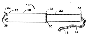
Referring to Figs. 1-8, a tampon applicator 10 is shown which is
designed to house a catamenial tampon 12 and provide a comfortable
means of inserting the tampon 12 into a woman's vagina. A tampon is
an absorbent member primarily designed to be worn by a woman during
her menstrual period to absorb menses, blood and other body fluid.
The tampon 12 can be made from natural or synthetic fibers including
cellulose fibers such as cotton or rayon, or artificial fibers such
as polyester, polypropylene, nylon or blends thereof. Other types of
fibers may also be used, such as cellulose sponge or a sponge formed
from elastomeric materials. A blend of cotton and rayon fibers works
well.
The tampon 12 is normally compressed into the form of a cylinder
and can have a blunt, rounded or shaped forward end. The tampon 12
commonly has a withdrawal string 14 fastened to an end thereof which
serves as a means for withdrawing the soiled tampon from the woman's
vagina. The withdrawal string 14 can be looped through an
aperture 16 formed ~,a.,,~.aely through the tampon 12. In addition,
the withdrawal string 14 can have a knot 18 formed at it's free end
to assure that the string 14 will not separate from the tampon 12.
The tampon applicator lO includes a first member 20 and a second
member 22. The first member 20 is preferably in the form of a
spirally wound, convolutely wound or longitud7nally seamed hollow
tube which is formed from paper, F boa.d, cardboard or a
combination thereof. The first member 20, also commonly referred to
as an outer tube, is falrly rigid and has a relatively small dlameter
of about 10 mm to about 20 mm. The first member 20 has a wall 24
with a predetermined thickness of about .2 mm to about .6 mm. The
wall 24 can be constructed from a single ply of material or be formed
~ 1 ' ' ' ~' '
WO 96105793 2~ :L 9 ~ ~ 9 3 PCIIIIS95110635
from two or more plies which are bonded together to form a laminate.
The use of two or more plies or layers is preferred for it enables
the I - ra-~,e to use certain material in the various layers which
can enhance the pe.ru" -? of the tampon applicator 10. When two or
more plies are utilized, all the plies can be spirally wound,
convolutely wound or longitudinally seamed to form an elongated
cylinder. The wall 24 can be constructed using a smooth thin ply of
material on the outside or exterior surface 26 which surrounds a
coarser and possibly thicker ply. When the wall 24 contains at least
three plies, the middle ply can be the thicker ply and the lnterior
and exterior plies can be smooth and/or slippery to facilitate
expulsion of the tampon 12 and to facilitate insertion of the first
member 20 into a woman's vagina, respectively. By sandwiching a
thick, coarser ply of material between two thin, smooth plies, an
inexpensive first member 20 can be provided which is very functional.
The wall 24 should contain one to four plies, although more plies can
be utilized if desired.
The plies forming the wall 24 can be held together by an
adhesive, such as glue, or by heat, pressure, ultrasonics, etc. The
adheslve can be either water-soluble or water-insoluble. A
water-soluble adhesive is preferred for environmental reasons in that
the wall 24 will quickly break apart when it is ~mmersed 1n water.
Such immersion will occur should the first member 20 be dlsposed of
by flushing it down a toilet. Exposure of the first member 20 to a
municipal's waste trêatment plant wherein soaking in water,
interaction with chemicals and agitation all occur, will cause the
wall 24 to break apart and evenly disperse in a relatively short
period of time.
The inside diameter of the first member 20 is usually less than
about .75 inches (about lg mm) and preferably less than about .625
inches (about 16 mm). Although the exterior diameter of tampons do
vary, most tampons utilized by women have an external diameter of
less than about .75 inches (about 19 mm). However, if one desired to
use this invention to administer medication to an animal, such as a
farm animal, larger size tampons 12 could be used.
2l96~93
~ WO 96/05793 - - PCT/US95/10635
It should be noted that the first member 20 can be spirally
wound, convolutely wound or longitudinally seamed into a cylindrical
tubular shape. Alternatively, the material can be overlapped into a
tubular configuration. Spirally or convolutely winding the first
~5 member 20 into a cylindrical tube is especially advantageous when the
first member 20 is formed from a laminate. The reason for this is
~that when a laminate is cir, '~ ially wound into a tube and a
butt seam or an overlap is formed, the butt seam or the overlap can
interfere with the later formation of pleats on the forward end
thereof. A common problem with a rigid or stiff walled, tubular
member having a relatively small diameter and a butt seam is that the
seam has a tendency to come apart after formation if exposed to
certain stress forces and/or high humidity. A problem with a tubular
member having an overlap is that a small portion of the wall will be
thicker than the remaining portion and this will cause problems when
one tries to pleat one end of the tube. Accordingly, the first
member 20 should preferably be formed into a cylindrical
configuration without the presence of a butt seam or an overlap.
The first member 20 is sized and configured to house the
absorbent tampon 12. As stated above, the first member 20 should
have a substantially smooth exterior surface 26 which will facilitate
insertion of the first member 20 into a woman's vagina. When the
exterior surface 26 is smooth and/or slippery, the first member 20
will easily slide into a woman's vagina without subjecting the
internal tissues of the vagina to abrasion. The first member 20 can
be coated to give it a high slip characteristic. Wax, polyethylene,
a combination of wax and polyethylene, cellophane and clay are
representative coatings that can be applied to the first member 20 to
facilitate comfortable insertion.
The first member 20 can be a straight, elongated cylindrical
tube formed on a central longitudinai axis X--X. It is also possible
to form the first member 20 into an arcuate shape. The arcuate or
curved shape can assist in providing comfort when inserting the first
member 20 into a woman's vagina. With a curved tampon applicator, it
is possible to employ a curved tampon which again may be more
comfortable for some women to use since the shape of the tampon may
better fit the curvature of a woman's vagina.
g
WO 96105793 ~, ~ 9 6 5 9 3 PCTIUS9~/1063~
The first member 20 has first and second spaced apart ends 28
and 30, respectively. The first member 20 can also have either a
constant outer diameter or a stepped outer profile. Preferably, the
first member 20 will have an essentially constant diameter over a
major portion of it's length. Integrally formed on the first end 28
of the first member 20 and extending outwardly therefrom is an
insertion tip 32. The insertion tip 32 is designed to facilitate
insertion of the first member 20 into a woman's vagina in a
comfortable manner. The insertion tip 32 is semi-spherical in
configuration and has a diameter which is ~pp~Oxh"ately equal to the
outside diameter of the first member 20. The insertion tip 32 has a
wall 34 with a thickness which is ~,u,u,u~i,,,~tely equal to the
thickness of the wall 24 which forms the first member 20. However,
it is possible to construct the wall 34 so that it has a thickness
which is less than or greater than the thickness of the wall 24, if
desired.
Referring to Fig. 4, the insertion tip 32 is shown tn
cross-section with the semi-spherical configuration extending outward
away from the first end 28 of the first member 20. The cross-section
of the semi-spherical configuration spans an arc (A) of approximately
180 degrees. The semi-spherical configuration is formed on a
diameter which is sized to be equal to or slightly smaller than the
diameter of the first member 20. For example, if the outslde
diameter of the first member 20 is .64 inches (16.2 mm), the
insertion tip 32 can be formed on a radius of about .32 inches (about
8.1 mm).
A relatively small aperture 36 is formed in the center of the
semi-spherical or dome shaped insertion tip 32 and is coax~ally
aligned with the longitudinal axis X--X. The aperture 36 can have a
diameter of at least about 1.5 mm, preferably between about 1.5 to
about 5.0 mm, and more preferably, between about 3.0 to about 3.5 mm.
Another way of sizing the diameter of the aperture 40 is to make it
less than about 30% of the dlameter of the first member 20,
preferably, between about 10% to about 30X of the diameter of the
first member 20, and most preferably, less than about 20% of the
diameter of the first member 20. lt should be noted that although
the aperture 36 is described as a circle, it is possible to form the
- 10 -
219~3
W096/05793 ' PCT/US95/10635
aperture 36 in other shapes such as a polygon, a square, a pentagon,
a hexagon, an octagon, etc. The small aperture 36 should extend
through the insertion tip 32 and have a side wall 38 which is aligned
essentially parallel to the longitudinal axis X--X. In addition, the
aperture 36 can be rounded or contain a radius 40 on it's exterior
surface to assure that no sharp edges are present which could pinch
or cut the sensitive tissues of a woman's vagina. The purpose of the
small aperture 36 in the end of the insertion tip 32 is to facilitate
the LLs- l unfolding of the pleats during use, as will be
described below. The aperture 36 also assures that the pleats will
symmetrically open about the longitudinal axis X--X of the first
member 20. A further benefit of the aperture 36 is that it provides
a visual means for the user to inspect the tampon applicator 10 and
assure herself that a tampon 12 is present in the first member 20.
The design in Fig. 4 is to be contrasted to the b~ l shown
in Fig. 5 wherein an enlarged aperture 42 is depicted having a side
wall 44 which tapers downward and inward to form a sharp point 46
adjacent to an interior surface 48 of the insertion tip 32. The
sharp point 46 is more likely to pinch or trap vaginal tissue and
therefore could cause discomfort during insertion. In addition, the
larger diameter of the aperture 42 exposes a greater area of the
absorbent tampon 12 and this could cause abrasion with the vaginal
tissues durlng insertion. The embodiment shown in Fig. 4 is more
desirable for comfort.
Referring again to Fig. 4, the configuration of the aperture 36
is preferred for it is smaller in diameter and therefore exposes a
smaller amount of the absorbent tampon 12. Since a tampon is
normally dry and consists of a plurality of absorbent fibers, it can
cause abrasion against the walls of a woman's vagina as it is being
inserted. By reducing the amount of surface area of the tampon 12
which is exposed to the vaginal tissue, one can decrease the
discomfort during the insertion process. In addition, since the
insertion tip 32 is al00st closed, it also lowers the frictional
force between the extertor surface 26 of the tampon applicator 10 and
the walls of the vagina. Furthermore, the small diameter of the
aperture 36 also decreases the possibility of trapping or pinching
vaginal tissue therein.
- 11 -
W0 96/05793 C~ 9 3 PCI/US95110635
Referring to Figs. 3, 6 and 7, the insertion tip 32 is shown
having a plurality of pleats 50 which can radially open such that the
insertion tip 32 has a diameter ~ r.v~i,,,dtely equal to or greater
than the diameter of the first member 20. Either an even or an odd
number of pleats 50 can be present and the pleats 50 can be equally
spaced apart or they can be non-un~formly arranged. Uniformly
arranged pleats 50 are preferred but randomly arranged pleats 50 will
work. For ease of , F~.~v,ing, it is preferred that the pleats 50
be equally spaced relative to one another. Each pleat 50 is a fold
formed by doubling the material upon itself and then pressing or
adhering the material into place. Although eight equally spaced
apart pleats 50 are shown in Fig. 3, it is possible to utilize
various numbers of pleats 50. The number of pleats 50 can vary from
between three to about thirty-two pleats, preferably between about 5
to about sixteen pleats, and most preferably, between about 6 to
about 12 pleats.
In Fig. 6, an . bu~i ~ is shown with three equally spaced
pleats 50, while in Fig. 7, sixteen pleats 50 are displayed. The
minimum number of pleats 50 should be no less than three because the
force required to open the insertion tip 32 normally increases as the
number of pleats 50 decrease. If the force becomes too large, the
tampon applicator 10 could bend or deform during the insertion
process and this may cause discomfort. When more than thirty-two
pleats 50 are used, the expulsion force may be lowered but it becomes
difficult to form so many pleats on the insertion tip 32.
Referring to Fig. 8, a schematic view of a pleat 50 is shown.
The pleat 50 is obtained by folding the paper, paperboard, or
cardboard material upon itself so that when each pleat 50 is opened
or unfolded it will occupy a much larger surface area. The thickness
of the material forming the insertion tip 32 can be equal to or
slightly less than the thickness of the first member 20. For the
first member 20, a thickness of about .1 mm to about .7 mm works
fine. The insertion tip 32 can have a thickness between about .1 mm
to about .5 mm. In the folded condition, the pleat 50 has a
thickness, indicated by the letter ~t" of less than about 0.7 mm,
preferably between about .25 mm to about .35 mm. Another way of
~ WO 96/05793 6S~3 = PCT/US9S/1063
stating this is to say that the thickness of each pleat 50 in the
folded condition will be greater than twice the thickness of the
material from which the insertion tip 32 is constructed.
Referring to Figs. 9-11, three different embodiments of a pleat
are depicted. In Fig. 9, the pleat 50 is depicted as having a first
end 52 which coincides with the side wall 38 of the aperture 36. In
other words, the first end 52 of the pleat 50 forms a portion of the
arc of the aperture 36. The pleat 50 also has a second end 54 which
coincides with a point located on the exterior surface 26 of the
first member 20. This point is spaced a distance "a" from tne
location where the insertion tip 32 is integrally joined to the first
member 20. By forming the pleat 50 with this particular length, one
can control the amount of force needed to open the insertion tip 32
and push the tampon 12 th ~lh,~ _ . Usually, a lower force is
required to open the pleats when each pleat 50 has a length which
extends into the outer cir, r~.~ of the first member 20.
In Fig. 9, the semi-spherical tip 32 spans a radial arc,
identified as angle alpha (a), which extends from the first end 52
to the point where the semi-spherical shaped tip 32 is integrally
joined to the first member 20. The angle alpha (a) iS between about
60- to about 90-, preferably between about 75- to about 90-, and most
preferably, greater than 80-. The angle alpha (a) would be 90- if
the aperture 36 was not present. The size of the aperture 36 will
partially determine the exact angle of the insertion tip 32. The
angle alpha (~) should be as close to 90- as possible without
completely enclosing the forward end of the tampon 12.
In Fig. 10, an alternative embodiment of an insertion tip 32' is
depicted wherein a pleat 50' is shown having a first end 52 which
coincides with the side wall 38 of the aperture 36. In other words,
the first end 52 of the pleat 50' forms a portion of the arc of the
aperture 36. The pleat 50' also has a second end 56 which coincides
with the point where the insertion tlp 32 is integrally joined to the
first end 28 of the first member 20. By forming the pleat 50' with
this particular length, one can control the amount of force needed to
open the insertion tip 32 and push the tampon 12 ~ lh.. _'.
W096/05793 2~965~ PCT/US95/10635
Although the force required to open the pleats 50' may be slightly
greater than the force required with the design shown in Fig. 9, the
force is still within acceptable limits.
In Fig. 11, a third embodiment of an insertion tip 32" is
deplcted wherein a pleat 50" is shown having a first end 52 which
coincides with the side wall 38 of the aperture 36. In other words,
the first end 52 of the pleat 50" forms a portion of the arc of the
aperture 36. The pleat 50" also has a second end 58 which coincides
with a point located on an exterior surface 60 of the insertion
tip 32. This point is spaced a distance "b" from the location where
the insertion tip 32 is integrally joined to the first end 28 of the
first member 20. By forming the pleat 50" with this particular
length, one can control the amount of force needed to open the
insertion tlp 32 and push the tampon 12 t~ e;h.~ _' . Although the
force required to open the pleats 50" may be greater than the force
required with the designs shown in Figs. 9 and 10, the force is still
within acceptable limits.
It should be noted that both the length and diameter of
commercially available tampons do vary and therefore the tampon
applicators 10 should be manufactured in a variety of sizes. Tampons
can vary in length from about 1 to about 3 inches (about 25.4 mm to
about 76.2 mm) but preferably are about 2 inches (about 50.8 mm) in
length. The tampon diameter will also vary from about .25 inches to
about .75 inches (about 6.4 mm to about 19.0 mm). In addition, the
material from which the tampon 12 is constructed, the t' --s of
the internal surface of the first member 20, the shape of the second
member 22, etc. all contribute to establish a needed expulsion force
to open and expel the tampon 12. This force should range from
between about 250 grams to about 1,500 grams, preferably less than
about 1,200 grams, and most preferably, less than about 1,000 grams.
A lower force value is preferred for it assures that the tampon
applicator 10 will be less susceptible to being bent or deformed as
the tampon 12 is expelled. A bent applicator could cause the tampon
to be inserted incorrectly. A lower force value also makes the
~ 35 tampon applicator 10 easier to use.
- 14 -
21 9 6~93
W096105793 PCT/US9S/1063S
Referring again to Figs. 1 and 2, the first member 20 can have a
fingergrip ring 62 located approximate the second end 30. The
fingergrip ring 62 can be integrally formed from the material from
which the first member 20 is constructed or it can be a separate
S member which is secured in place by an adhesive or some other type of
attachment mechanism. The fingergrip ring 62 functions to provide a
means for the user to grip the first member 20 and hold it between
her thumb and middle flnger. The user can then position her
forefinger on the free end of the second member 22 and orient the
first member 20 relative to her vagina while she pushes the second
member 22 into the first member 20.
As stated above, the tampon applicator 10 includes a second
member 22, also commonly referred to as an inner tube. The second
member 22, like the first member 20, can be a spirally wound~ a
convolutely wound or a longitudinally seamed hollow tube constructed
from paper, paperboard, cardboard, or a combination thereof. The
second member 22 can also be formed into a cylindrical tube by
overlapping the material upon itself. The second member 22 can be
constructed of the same material as the first member 20 or it can be
made out of a different material. Fu.;- .c, the second member 22
could be constructed as a laminate having two or more plies which are
then spirally wound, convolutely wound or longitudinally seamed into
a cylindrical tube. Either a wound tube or a longitudinally seamed
tube is preferred because the finished tube will have a wall 64 with
a constant thickness. However, some , rccL~,~ s may prefer to
construct the second member 22 as a solid stick or use some other
unique shape. It is also possible to form a fingergrip ring or
flange 66 on the outer end of the second member 22 to provide an
enlarged surface onto which the user's forefinger can rest. The
fingergrip ring 66 thereby functions as a seat for the forefinger and
facilitates movement of the second member 22 into the first
member 20.
Referring to Fig. 12, the second member 22 functions by being
telescopically movable relative to the first member 20. As the
second member 22 is pushed into the first member 20, the tampon 12 is
forced forward against the pleats 50. The contact by the tampon 12
causes the pleats 50 to radially open to a diameter which is
. . .
- 15 -
~v096/05793 219 6 59 3 PCTIUS95/10635
sufficient to allow the tampon 12 to be expelled from the first
member 20. The open a~, ~ L of the pleats 50 is shown in Fig. 12
after the tampon 12 has been expelled. With the tampon 12 properly
positioned in the woman's vaginal cavity, the tampon applicator 10 is
withdrawn and properly discarded.
The tampon applicator 10 having the semi-spherically shaped
insertion tip 32 works well in combination with a catamenial tampon
having a shaped nose. This is especially true when the shaped nose
on the tampon 12 is configured to conform to the interior surface 48
of the insertion tip 32.
Referring to Figs. 13-15, a tampon applicator 110 is shown which
is designed to house an absorbent tampon 112 and provide a
comfortable means of inserting the tampon 112 into a woman's vagina.
A tampon is an absorbent member primarily designed to be worn by a
woman during her menstrual period to absorb menses, blood and other
body fluid. The tampon 112 can be made from natural or synthetic
fibers including cellulose fibers such as cotton or rayon, or
artificial fibers such as polyester, polypropylene, nylon or blends
thereof. Other types of fibers may also be used, such as cellulose
sponge or a sponge formed from elastomeric materials. A blend of
cotton and rayon fibers works well.
The tampon 112 is normally e,sed into the form of a
cylinder and can have a blunt, rounded or shaped forward end. The
tampon 112 commonly has a withdrawal string 114 fastened to an end
thereof which serves as a means for withdrawing the soiled tampon
from the woman's vagina. The withdrawal string 114 is permanently
affixed to the tampon 112, for example, by looping it through an
aperture 116 formed transversely through the tampon 112. In
addition, the withdrawal string 114 can have a knot 118 formed at
it's free end to assure that the string 114 will not separate from
the tampon 112.
The tampon applicator 110 includes an outer tube 120 and an
inner tube 122. The outer tube 120 is preferably in the form of a
spirally wound, convolutely wound or longitudinally seamed, hollow
tube which is formed from paper, paperboard, cardboard or a
combination thereof. The lnner tube 122 can be formed from the same
material as the outer tube 120, or alternatively, be made of a
. , .
- 16 -
~ W0 96/05793 2 1 9 6 5 9 3 PCT/US95/10635
different material. The inner tube 122 should have a constant
external diameter so as to easily slide with1n the inner diameter of
the outer tube 120. It is also possible to construct the inner
tube 122 as a solid stick, or use some other unique shape, which
attaches directly to the tampon 112.
Both the outer tube 120 and the inner tube 122 are fairly rigid
and commonly have a diameter of about 10 mm to about 20 mm, with the
inner tube 122 being slightly smaller in diameter than the outer
tube 120. The outer tube 120 has a wall 124 with a predetermined
thickness of about .2 mm to about .6 mm. The inner tube has a
wall 126 which is slightly thinner. The walls 124 and 126 can be
constructed from a single ply of material or be formed from two or
more plies which are bonded together to form a laminate. The use of
two or more plies or layers is preferred for it enables the
manufacturer to use certain material in the various layers which can
enhance the pc.ru., of the tampon applicator 110. When two or
more layers are utilized, all the layers can be spirally wound,
convolutely wound or longitudinally seamed to form an elongated
cylinder. The exterior surface of the wall 124 can be Lr. Led
using a smooth thin layer of material to facilitate insertion of the
first member 120 into a woman's vagina.
The layers forming the walls 124 and 126 can be held together by
an adhesive, such as glue, or by heat, pressure, ultrasonics, etc.
The adhesive can be either water-soluble or water-insoluble. A
water-soluble adhesive is preferred for environmental reasons in that
the tubes 120 and 122 will quickly break apart when immersed in
water. Such immersion will occur should the tubes 120 and 122 be
disposed of by flushing them down a toilet. Exposure of the
tubes 120 and 122 to a municipal's waste treatment plant wherein
soaking in water, interaction with chemicals and agitation all occur,
will cause the tubes 120 and 122 to break apart in a relatively short
period of time.
The outer tube 120 is sized and configured to house the
absorbent tampon 112 and the inner tube 122 is sized and configured
to push the tampon 112 out of the outer tube 120. The outer tube 120
can be a straight, elongated cylindrical tube formed on a central
longitudtnal axis X--X. It is also possible to form the outer
w 096~5793 2 i 9 6 ~ 9 3 PCTrUS95/10635
tube 120 into an arcuate shape. The arcuate or curved shape can
assist in providing comfort when inserting the outer tube 120 into a
woman's vagina. The inner tube 122 should be configured to
telescopically slide in the outer tube 120. With a curved tampon
applicator, it is possible to employ a curved tampon which again may
be more comfortable for some women to use since the shape of the
tampon may better fit the curvature of a woman's vagina.
The outer tube 12û has first and second spaced apart ends 128
and 130, respectively. The outer tube 120 can also have either a
constant outer diameter or a stepped outer profile. Preferably, the
outer tube 120 will have an essentially constant diameter over a
major portion of it's length. Integrally formed on the first end 128
of the outer tube 120 and extending outwardly therefrom is an
insertion tip 132. The insertion tip 132 is designed to facilitate
insertion of the outer tube 120 into a woman's vag~na in a
comfortable manner. The lnsertion tip 132 contains a number of
pleats 134 and has a semi-spherical configuration with a diameter
which is approximately equal to the outside diameter of the outer
tube 120. The pleats 134 can be uniformly spaced apart or they can
be randomly arranged. The insertion tip 132 can have the same
thjckness as the outer tube 120 or be made thinner or thicker, if
desired.
An aperture 136 is formed in the center of the sem~-spherical
shaped insert~on tip 132 and is coaxially aligned with the
longitudinal axis X--X. The aperture 136 can have a diameter of at
least about 1.5 mm, preferably between about 1.5 to about 5.0 mm, and
more preferably, between about 3.0 to about 3.5 mm. Another way of
sizing the diameter of the aperture 136 is to make it less than about
30% of the diameter of the outer tube 120, preferably, between about
10X to about 30%, and most preferably, less than about 20X of the
diameter of the outer tube 120. It should be noted that although the
aperture 136 is described as a circle, it is posslble to form the
aperture 136 in other shapes such as a polygon, a square, a pentagon,
a hexagon, an octagon, etc. The aperture 136 should extend entirely
through the insertion tip 132. The purpose of the aperture 136 in
the end of the insertion tip 132 is to facilitate the ' e,
unfolding of the pleats 134 during use. The aperture 136 also
- 18 -
2l96593
W096/05793 PCT/US95110635
assures that the pleats 134 will symmetrically open about the
longitudinal axis X--X of the outer tube 120. A further benefit of
the aperture 136 is that it provides a visual means for the user to
inspect the tampon applicator 110 and assure herself that a
- 5 tampon 112 is present in the outer tube 120.
With the aperture 136 being small, less of the absorbent
tampon 112 is exposed to the vaginal tissue when the tampon
applicator 110 is inserted into the woman's vagina. Since a
tampon 112 is normally dry and consists of a plurality of absorbent
fibers, it can cause abrasion against the walls of a woman's vagina
as it is being inserted. By reducing the amount of surface area of
the tampon 112 which is exposed to the vaginal tissue, one can
decrease the discomfort during the insertion process. In addition,
since a majority of the insertion tip 132 is closed, the frictlonal
force between the exterior surface 126 of the outer tube 120 and the
walls of the vagina is reduced. Fu~ , the small diameter of
the aperture 136 also decreases the possibility of trapping or
pinching vaginal tlssue therein.
Referring to Figs. 15 and 16, the insertion tip 132 is shown
having a plurality of pleats 134 which can radially open such that
the insertion tip 132 has a diameter which is approximately equal to
or larger than the diameter of the outer tube 120. The term "pleat"
as used herein refers to material which is folded upon itself, for
example, by doubling the material upon itself and then pressing it
into place. A representative view of a pleat 134 is depicted in
Fig. 16. Either an even or an odd number of pleats 34 can be present
and the pleats 34 can be equally spaced apart or they can be
uniformly or randomly arranged. For ease of ~ Fa~,ing, it is
preferred that the pleats 34 be equally spaced relative to one
another. Each pleat 34 is formed by doubling the material upon
itself and then pressing or adhering the material into place.
Although eight equally spaced apart pleats 34 are shown in Fig. 15,
it is possible to utilize various numbers of pleats 34. The number
of pleats 34 can vary from between three to about thirty-two pleats,
preferably between five to sixteen pleats, and most preferably, eight
pleats.
- 19 -
w 096/05793 2 1 9 6 5 ~ 3 r ~ r PCT/US95/10635
Referring again to Figs. 13 and 14, the outer tube 120 can have
a fingergrip ring 138 located ap~uAi~ te the second end 130. The
fingergrip ring 138 can be integrally formed from the material from
which the outer tube 120 is constructed or it can be a separate
member which is secured in place by an adhesive or some other type of
attachment mechanism. The fingergrip ring 138 functions to provide a
means for the user to grip the outer tube 120 and hold it between her
thumb and middle finger. The user can then position her forefinger
on the free end of the inner tube 122 and orient the outer tube 120
relative to her vagina while she pushes the inner tube 122 into the
outer tube 120.
The inner tube 122 can have an inwardly directed flange 140
formed at its forward end which provides an enlarged surface for
contacting the rear end of the tampon 112. The inner tube 122 can
also have a radial, outwardly extending ring 142 formed adjacent to
the outer or free end of the inner tube 122 which provides an
enlarged surface onto which the user's forefinger can rest. The
ring 142 thereby functions as a seat for the forefinger and
facilitates movement of the inner tube 122 into the outer tube 120.
The inner tube 122 functions by being telescopically movable
relatjve to the outer tube 120. As the inner tube 122 is pushed into
the outer tube 120, the tampon 112 is forced forward against the
pleats 134. The contact by the tampon 112 causes the pleats 134 to
radially open to a diameter which is sufficient to allow the
tampon 112 to be expelled from the outer tube 120. With the
tampon 112 properly positioned in the woman's vaglna, the tampon
applicator 110 is withdrawn and properly discarded.
APPARATUS
~he outer tube 120 can have the insertion tip 132 formed into
the desired semi-spherical configuration with the central
aperture 136 by using the apparatus described below.
Referring to Figs; 17 and 18, the outer tube 120 is shown before
the insertion tip 132 is formed. At this stage, the outer tube 120
has an essentially constant inside diameter and the wall 124 has a
constant thickness.
- 20 -
W096/05793 ~9~S~ PCT/US95/10635
Referring to Figs. 19 and 20, a first punch 144 is shown having
a tubular section 146 which is sized and configured to receive the
outer tube 120. ln other words, the outer tube 120 must be able to
slide onto the tubular section 146 with only a small amount of
clearance th_,.bci ~!~. The first punch 144 has a tip 148. The
tip 148 can be smooth or void of any grooves as shown in Fig. 19.
Alternatively, the first punch 144' can have a configured tip 148
with a plurality of elongated grooves 150 formed therein, as is
depicted in Fig. 20. When the grooves 150 are present, there should
be at least four grooves 150, preferably between eight to twelve
grooves 150, with eight grooves 150 being most preferred. The
purpose of the grooves 150 will be explained shortly.
The tip 148 can be formed into a frusto-conical shape having a
blunt end 152. Other shapes can also be utilized if desired. At
least a portion of the exterior surface of the tip 148 can be
knurled 154 to provide a frictional surface between the tip 148 and
the inner surface of the outer tube 120 as the insertion tip 132 is
being formed. A medium knurl 154 will provide an adequate frictional
surface for the crimping operation. The first punch 144 or 144' also
has a shoulder 156 formed at an opposite end of the tubular
section 146 which acts as a stop for the outer tube 120. It should
be noted that the lensth of the tubular section 146 is sized to
conform closely to the length of the outer tube 120. A typical outer
tube 120 will have a length of between about 2 inches to about 4
inches (about 50.8 mm to about 101.6 mm), preferably about 3 inches
to about 3.5 inches (about 76.2 mm to about 88.9 mm), most
preferably, at least about 3.12 inches (about 79.2 mm). The tubular
section 146 should have a length which is equal to or slightly
greater than the initial length of the outer tube 120 as shown in
Fig. 17. The first end 128 of the tube 120 can be aligned
app~i",~tely flush with the tip 148 when the tube 120 is positioned
on the tubular section 146. However, an extra length of about 0.06
inches (about 1.5 mm) on the tubular section 146 of the first
punch 144 or 144' is advantageous for permitting the first punch 144
or 144' to mate with a first die 158.
W096/05793 593 PCT/US95110635
Referring to Figs. 20 and 21; the first punch 144' is shown with
the outer tube 120 slid onto the tubular section 146 such that the
second end 130 of the outer tube 120 abuts the shoulder 156 and is
matëable with the first die 158. The axial : , 3 t of both the
first punch 144' and the outer tube 120 with the first die 158
enables the tip 132 of the outer tube 120 to be crimped. The term
"crimped" as used herein refers to pressing or pinching the material
forming the insertion tlp 132 into small, regular folds or ridges
with troughs th- cb_L - .
Referring to Figs. 22 and 23, the crimped tip 160 consists of a
plurality of ridges 162 and troughs 164 formed about the
cir. r~,. of the first end 128 of the outer tube 120. The
troughs 164 are the deepest adjacent the first end 128 and become
shallower as the troughs move away from the first end 128. The
ridges 162 are formed on a circle having a smaller diameter adjacent
the first end 128 and expand outward as the ridges 162 move away from
the first end 128.
Referring again to Figs. 20 and 21, the crimped tip 160 is
formed by the ~ , L of the first punch 144 or 144' with the
first die 158. The first die 158 includes a base 166 having a
plurality of blades 168 extending axially outward therefrom. There
should be at least four blades 168, preferably, between eight to
twelve blades, w1th eight blades being the most preferred. For best
results with hard board papers, each groove 150 formed in the first
punch 144' should align wlth i blade 168 formed in the first die 158.
Either an even number or an odd number of blades 168 can be utilized.
An even number of blades 168 are easier to machine and the first
die 158 will then have a symmetrical shape, which is also
advantageous. For example, symmetrically shaped dies can be measured
across their tips to determine their s1ze.
The blades 168 can range from about .5 inches (about 12.7 mm) to
about 2 inches (about 50.8 mm) in length. A length of approximately
1 inch (25.4 mm) is sufficient. The blades 168 have an angled or
tapered inner surface 170 which enables then to mate wtth the smooth
tip 148 formed on the first punch 144 or mate with and axially enter
a co" esr ~ing groove 150 formed in the flrst punch 144'. The angle
can vary depending upon the taper on the smooth tip 148 or depending
- 22 -
~ w os6/0s793 2 1 9 6 5 g 3 1 ~ Jt~ s
on the angle at which each cu,,,~r 'ing groove 150 is formed. The
angle on each blade 168 can be equal to or different from the angle
formed on the smooth tip 148 and can also be equal to or different
from the angle to which each groove 150 is machined. When the
grooves 150 are present, each groove 150 should be sized to be larger
than the cu" ~suu,,ding blade 168 so that the thickness of wall 124 of
the outer tube 120 can also be received into the grooves 150. Each
blade 168 is machined to an angle which is different from the angle
to which the bottom of the grooves 150 have been machined to. When
the first punch 144' is fully inserted into the first die 15$, the
angled surfaces 170 of each blade 168 is spaced apart from the bottom
of each cu,.e_r iing groove 150. This clearance permits the wall
thickness of the outer tube 120 to be sandwiched ~ e' l and
provides the undulating surface which is the crimp 160 shown in
Fig. 23. The angle that each groove 150 and each blade 168 is formed
at can vary. The grooves 150 and the blades 168 can be formed at
identical angles relative to a longitudinal central axis Y--Y of the
first punch 144' and the first die 158, or they can be formed at
different angles relative to one another. For outer tubes 120 formed
from hard P~r~ bùu.d, good quality pleats 134 can be formed using the
first punch 144 with the smooth t1p 148 mating with the first
die 158. For softer paperboard, it is advantageous to machine an
angle of about 20- to the Y--Y axis in the first die 158 and to
machine an angle of about 15- to the Y--Y axis in the first
punch 144'.
Referring to Fig. 21, one can see the position of the outer
tube 120 on the first punch 144' while the first end 128 is crimped.
The knurled surface 154 serves to prevent the outer tube 120 from
moving toward the shoulder 156 when the first punch 144' engages the
first die 158. It has been found that the force exerted on the outer
tube 120 increases as the first punch 144 or 144' engages deeper and
deeper into the first die 158. When the knurled surface 154 is not
present, this force can drive the outer tube 120 up against the
shoulder 156 and cause the second end 130 of the outer tube 120 to
become wrinkled and radially enlarged. Such a feature is not
aesthetically pleasing and must be avoided.
- 23 -
WO 96/05793 2 ~9 ~ PCT/~JS95/10635
After the outer tube 120 has a crtmped tip 160 formed on the
first end 128 thereof, the first punch 144 or 144' and the first
die 158 are separated and the outer tube 120 is removed.
Referring to Figs. 24 and 25, the outer tube 120 is then
sub~ected to a second operation wherein the crimped tip 160 is
pleated and pressed into a semi-spherical configuration. This is
accomplished by using a second punch 172 having a tubular section 174
which is sized to receive the outer tube 120. The second punch 172
has a semi-spherically shaped tip 176 with a pin 178 extending
outward from the apex of the tip 176. The pin 178 has a distal or
free end 180. The second punch 172 also contains a shoulder 182
formed at an opposite end of the tubular section 174 which acts as a
stop for the outer tube 120. It should be noted that the length of
the tubular section 174 is sized to conform closely to the length of
the outer tube 120. The second punch 172 is designed to have the
outer tube 120 slid over the tubular section 174 until the second
end 130 of the outer tube 120 abuts against the shoulder 182. In
this position, the crimped tip 160 formed on the first end 128 of the
outer tube 120 should extend about 0.06 inches to about 0.12 inches
(about 1.5 mm to about 3.0 mm) beyond the apex of the
semi-spherically shaped tip 176. The free end 180 of the pin 178,
however, will extend beyond the crimped end 160 by at least 0.06
inches (1.5 mm), and preferably more.
At least a portion of the semi-spherically shaped tip 176 can be
knurled 184 to provide a frictional surface between the tip 176 and
the inner surface of the outer tube 120 as the insertion tip 132 is
being formed. A medlum knurl 184 wlll provide an adequate frictional
surface for the pleating and forming operation. The knurled
surface 184 serves to prevent the outer tube 120 from moving toward
the shoulder 182 of the second punch 172.
The pin 178 can have a length of at least 0.06 inches (1.5 mm)
but is preferably longer. The pin 178 should have a diameter of at
least 0.062 inches (1.5 mm), preferably at least 0.125 inches (3.1
mm), and can be larger if desired. The cross-section of the pin 178
is preferably circular but could be of a different configuration if
desired. A circular cross-section is preferred for it forms an
opening with a circular periphery. A circular opening is
- 24 -
~ WO 96/OS793 21, 9 ~ 5 9 3 PCT/US9S/10635
aesthetically pleasing to the eye and since one of the purposes of
the aperture 136 is to allow the consumer to see if a tampon 112 is
present in the tampon applicator 110, the aperture could be circular.
The pin 178 is shown having an essentially constant outside diameter.
However, it is possible to form the pin 178 such that 1t tapers down
in diameter from a larger diameter located adjacent to the point of
attachment to the apex of the semi-spherical tip 176 to a smaller
diameter adjacent the free end 180.
The second punch 172 is sized and configured to engage with a
second die 186 so as to transform the crimped tip 160 of the outer
tube 120 into a plurality of pleats 134 and form the pleats 134 into
a semi-spherically shaped tip 190, see Figs. 26 and 27. The
pleats 134 can be uniformly or randomly spaced apart and can have a
dovetail-like appr~r -:r. The length of each pleat 134 should be
aligned ar,x.u~i",dtely straight with or parallel to the longitudinal
axis of the tube 120 versus being undulating or curved. A straight
pleat normally requires a lesser amount of force to open. The
pleats 134 should terminate at a point 188 which is ,~ vxin,~tely
tangent to the point where the semi-spherically shaped tip 190 joins
to the exterior surface of the outer tube 120. The semi-spherically
shaped tip 190 will have a central aperture 192 formed therethrough
because of the presence of the pin 178. The aperture 192 allows the
consumer to visually inspect the tampon applicator 10 to see if a
tampon 112 is present. The aperture 192 can vary with the diameter
of the tube 120 but should not be so large that tt would allow a
woman to feel it as she inserts the tampon 112 into her vagina. If
the aperture 192 is too large, it could cause discomfort as the woman
inserts the tampon applicator 110 into her vagina.
Referring again to Figs. 24 and 25, the second die 186 includes
a base 194 having a first end 196 and a second end 198. A
semi-spherically shaped cavtty 200 formed in the base 1g4 adjacent to
the first end 196. The semi-spherically shaped cavity 200 is sized
to receive the semi-spherically shaped tip 176 formed on the outer
tube 120 as well as the wall thickness of the outer tube 120. This
difference in size will allow the insertion tip 132 to be formed on
the first end 128 of the outer tube 120. The surface of the
cavity 200 is preferably polished to improve the appearance of the
- 25 -
wos6l0s7s3 2~ r~l~u~ o635 ~
finished semi-spherically shaped tip 176 and to facilitate removal of
the finished tube 120 from the second die 186. The polished surface
can have a "surface roughness average" value of between about 4 micro
inches to about 16 micro inches.
The base 194 also has a central passageway 202 formed therein
which is axially aligned along a longitudinal central axis Z--Z. The
passageway 202 extends from the bottom of the cavity 200 to the
second end 198. If desired, the p~s~ -ay 202 can be a closed
passageway which terminates short of the second end 198. The
passageway 202 is slzed and configured to receive only the pin 178.
The outside diameter of the pin 178 should be slightly smaller than
the inside diameter of the passageway 202. The relationship between
the mating second punch 172, the outer tube 120 and the second
die 186 is clearly shown in Fig. 25.
It should be noted that both the length and diameter of
commercially available tampons do vary and therefore the tampon
applicator 110 should be manufactured in a variety of sizes. Tampons
can vary in length from about 1 inch to about 3 inches (about 25.4 mm
to about 76.2 mm) but preferably are about 2 inches (about 50.8 mm)
in length. The tampon diameter will also vary from about .25 inches
to about .75 inches (about 6.4 mm to about 19.0 mm). In add1tion,
the material from which the tampon 112 is constructed, the 1' -ss
of the internal surface of the outer tube 120, the shape of the inner
tube 122, etc. all contribute to establish a needed expulsion force
to open and expel the tampon 112. This force should range from
between about 250 grams to about 1,500 grams, preferably less than
about 1,200 grams, and most preferably, less than about 1,000 grams.
A lower force value is preferred for it assures that the tampon
applicator 110 will be less susceptible to being bent or deformed as
the tampon 112 is expelled. A bent applicator could cause the tampon
to be inserted ~ncorrectly. A lower force value also makes the
tampon applicator 110 easier to use. The size of the aperture 192
will also affect the amount of force needed to open the pleats 134.
Typically, the larger the diameter of the aperture 192, the lower the
force required to open the pleats 134.
- 26 -
~ W 096105793 %19~93 r~l~u~ s~
METH~D
The method of crimping, pleating and forming a semi-spherically
shaped tip 190 on a hollow tube 120 is as follows, using the
above-identified punches 144, 144' and 172, and dies 158 and 186.
S The above identified punches 144, 144' and 172, and dies 158 and 186
can be manually or automatically engaged and disengaged to form the
insertion tip 132 on the outer tube 120. It is contemplated that the
punches 144, 144' and 172, and the dies 158 and 186 will be actuated
at sufficient speeds to crimp, pleat and form in excess of 100,
preferably in excess of 300, and most preferably, more than 500 outer
tubes per minute.
The method involves sliding the hollow tube 120 onto the first
punch 144 or 144' until one end 130 of the tube 120 contacts the
shoulder 156. The first punch 144 or 144' and the tube 120 are moved
into ~ with the first die 158 and a plurality of crimps are
formed on the opposite end 128 of the tube 120. The plurality of
crimps form the crimped end 160. The first punch 144 or 144' is then
disengaged from the first die 158 and the tube 120 having the crimped
end 160 is removed from the first punch 144 or 144'. The tube 120 is
then slid onto the second punch 172 until the non-crimped end 130 of
the tube 120 contacts the shoulder 182. The second punch 172 and the
tube 120 are brought into _ ~ with the second die 186 thereby
allowing the axially extending pin 178 to enter the passageway 202.
The mating of the second punch 172 with the second die 186 L, rO.~..S
the crimped end 160 of the tube 120 into a plurality of pleats 134
and forms the pleats 134 into a semi-spherically shaped tip 190
having a central aperture 192 formed t' ~i r~ ~ . Once the tip 190
is formed, the second punch 172 is disengaged from the second die 186
and the outer tube 120 is removed from the second punch 172.
While the invention has been described in conjunction with
several specific _ b~ s, it is to be ; ' ~ood that many
alternatives, modificat~ons and variations will be apparent to those
skilled in the art in light of the aforegoing description.
Accordingly, this invention is intended to embrace all such
alternatives, modifications and variations which fall within the
spirit and scope of the appended claims.