Note: Descriptions are shown in the official language in which they were submitted.
wos6/03ssz r~l,L~
.
2 I q659
A PROCESS FOR ASSEMBLING ELASTICIZED EAR PORTIONS
Field of the Invention
The present inventlon relates to a method for forming an elasticized
article. More particularly, the invention relates to a method for
forming an article wherein elasticized side panel webs are connected to a
web of bridge material to provide for a composite bridge member which can
be more efficiently assembled into the artlcle.
Backaround of the Invention
Conventional absorbent articles, such as disposable diapers, have been
constructed with elasticized waistbands. Particular article designs have
incorporated a stretchable outer cover composed of an elastomeric web
material, such as a stretch bonded laminate which includes a layer of
nonwoven fabric. Other conventional designs have included elastomeric
side panel members connected to the lateral side edges of a polymer film
material. For example, see U.S. Patent 4,86l,652 to Lippert et al.; U.S.
Patent 4,70l,l70 issued October 20, l987, to Wilson et al.; and U.S.
Patent 5,0l9,073 issued May 28, l99l, to Roessler et al.
Conventional techniques for forming articles with elasticized side panel
portions have not been adequate for incorporation into high speed
Fa.L~,;ng systems. lt has, for example, been difficult to maintain a
desired cross-directional spacing and/or alignment between the
elastomeric panels positioned at opposed side edges of the art1cle. In
addition, the conventional techniques have not provided adequate control
of the side panel members during the r~.Lu,ing process. Undesired
movements of the elastomeric side panel members and other components or
component assemblies can undesirably interfere with the manufacturing
process.
WO 96/03952 P~
2 1 96~98
Brief Descriotion of the Inventlon
A process aspect of the invention provides a method for forming an
elasticized article which includes the steps of providing first and
second webs of elasticized side panel material. The side panel material
is constructed to be elastically stretchable at least along an appointed
lateral, cross-direction. At least one first fastener is attached to the
flrst web of slde panel material, and at least one second fastener is
attached to the second web of side panel material. The first web of side
panel material is attached to a first side edge region of a web of bridge
I0 material, and the second web of side panel material is attached to a
second side edge region of the web of bridge material. The second web of
side panel material is arranged to provide a cross-directional alignment
between at least one c~ u"ding, laterally opposed pair of the first
and second fasteners. The web of bridge material and the first and
lS second webs of side panel material are divided to provide at least one
composite bridge assembly having a bridge member interconnecting a
laterally opposed palr of first and second side panel members. The
composite bridge member is secured to an article web with the first and
second side panel members located at opposite side regions of the art1cle
web.
A further aspect of the process of the invention can further include the
steps of providing a web of backsheet material, and positionlng at least
one absorbent body at a selected location along a machine-directlon
length of the backsheet web. A web of topsheet material is provided to
sandwich the absorbent body between the web of backsheet material and the
web of topsheet material. At least one composite bridge assembly ls
connected to at least one of the backsheet and topsheet layers with the
bridge materlal arranged in an overlapping relation with a longitudinal
end section of the absorbent body.
In its various aspects, the process of the invention can more efficiently
produce elasticized articles at high speed. The process can provide a
more accurate placement of elasticized side panel material at the
appointed waistband edges of each appointed article segment. There can
be a more accurate alignment of the fasteners at laterally opposed side
regions of each appointed article. Where the fastening mechanisms employ
adhesive se~ul~ L, the fasteners can be better protected from
- 2 -
w os6/03ss2 ~ 1 9 65 9 ~ PCT/US95/08895
contamination. The various aspects of the article of the invention can
advantageously provide improved resistance to leakage, particularly
leakage at the waistband regions of the article. The articles can have
more consistent quality and can provide more consistent F r~., due
to the more accurate and secure placement and cross-dlrectional alignment
between the opposed pair of elastomeric side panels. In additlon, the
more accurate and secure placement and alignment of the fasteners can
provide improved ap~ezld"~e and fit on the wearer.
Iû Brief DescriDtion of the Drawinùs
The invention will be more fully understood and further advantages will
become apparent when reference is made to the following detailed
description and 1~ ying drawings in which:
Fig. 1 representatively shows a schematic of a process of the inventionconfigured to position a bridge member adjacent a major facing surface,
such as an outerside surface, of the backsheet web layer;
Fig. 2 representatively shows a schematic of the process of the invention
configured to place a bridge member generally adjacent an outwardly
facing surface of the topsheet web layer;
Fig. 3 representatively shows a perspective view of an article web
produced by the process of the invention illustrated in Fig. 2;
Fig. 4 representatively shows a schematic of the process of the invention
configured to position a bridge member adjacent a bodyside surface of the
topsheet web layer;
Fig. 5 representatively shows a perspective view of an article web
produced by the process of the invention illustrated in Fig. 4;
Fig. 6 representatively shows a schematic of the process of the invention
configured to apply onto each appointed bridge member a shaped pattern
area of adhesive which attaches the bridge member into the assembled
article;
wos6/oas~2 21 9 6 5 q 8 r~"u~ ~ s
Fig. 7 representatively shows a schematic of the process of the invention
configured to position a brldge member adiacent a bodyside surface of the
topsheet web layer in an ali_ L overlying the bodyslde surfaces of a
pair of longitudinally extending containment flaps; and
Fig. 8 representatively shows a perspective vlew of an artlcle web
produced by the process of the invention illustrated in Fig. 6.
Detailed DescriDtion of the Invention
I0 The method and apparatus of the present invention will be described
herein in relationship to their use in disposable absorbent art~cles, but
it should be understood that potential uses of the method and apparatus
of the present invention need not be limited to disposable absorbent
articles. As used herein, the term "disposable absorbent article" refers
to articles which absorb and contain body exudates and are lntended to be
discarded after a llmited period of use. The articles are not intended
to be laundered or otherwise restored for re~use. ~he articles can be
placed against or in proximity to the body of a wearer to absorb and
contain various exudates discharged from the body. While the present
descriptlon will particularly be made in the context of a diaper article,
it should be understood that the present invention is also applicable to
other disposable personal care absorbent articles, such as adult
incontinence garments, sanitary napkins, chlldren's training pants, and
the like.
The present invention can advantageously be employed to more effic1ently
produce improved absorbent articles havlng a front waistband section, a
rear waistband sectlon and an intermediate section which int~, ~ s
the front and rear waistband sections. The article includes a backsheet
layer having a laterally extending width and a longitudinally extending
length. A liquid permeable topsheet layer is su~ osed on the backsheet
layer, and the topsheet layer has a laterally extending width and a
longitudinally extending length. An absorbent body is located between
the backsheet layer and the topsheet layer, and an elasticized side panel
is connected to the article at each laterally opposed end region of at
least one of the front and rear waistband sections. The side panels are
~ 1u~ed to be elastically stretchable at least along a lateral,
cross-directlon of the article. A bridge member, which is separate from
- 4 -
w096/039~2 2 1 ~6598 P~ , c
the backsheet and topsheet layers, extends laterally to interconnect
between the elasticized side panels. The bridge member can be arranged
in an overlapping relation with a longitudinal end section of the
absorbent body, and is operably connected to at least one of the
backsheet and topsheet layers. A fastening means for securing the
article on a wearer is connected to a laterally distal end region of at
least one, and preferably both, of the side panels. Various
configurations of such articles are described in U.S. Patent Application
Serial No. of D. Fries et al., entitled ABSORBENT
ARTICLE WITH ELASTICIZED SIDE PANELS CONNECTED BY A BRIDGE MEMBER and
filed (Attorney docket No. 11,426), the disclosure of
which is hereby incorporated by reference in a manner that ls consistent
(not contradictory) herewith.
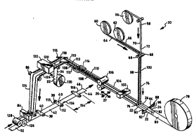
With reference to Fig. 1, a process aspect of the invention shown
generally at ZO provides a distinctive method for forming an elasticized
article, such as an elasticized disposable diaper. The method includes
the steps of providing a first web of elasticized side panel material 22
and a second web of elast1cized side panel materlal 24. The side panel
materlal is co,.,L-, ~d to be elastically stretchable at least along an
appointed lateral cross- direction of the process. At least a first
fastener, such as fastening tab 112, can be attached to the first web of
side panel material 22, and at least a second fastener, such as fastening
tab 113, can be attached to the second web of side panel material 24. A
web of bridge material has a first side edge 34 and a second side
edge 36. In the shown configuratlon, the web of bridge material is a web
-L~ 1 separate from the other components of the diaper article, and
the web of bridge material is operably provided into the process. The
first web of side panel material 22 is attached to the first side edge
region 34 of the web of bridge material 32. Similarly, the second web of
slde panel material 24 is operably attached to the second side edge
region 36 of the web of bridge material 32. The second web of side panel
material is arranged to provide a cross-directional alignment between at
least one C~~-r ling, laterally opposed pair of the first and second
fasteners 112 and 113, respectively. The web of bridge material 32 and
the first and second webs of side panel material 22 and 24 are divided to
provide at least one composite bridge assembly 38 having a bridge
member 40 interconnecting the laterally opposed pair of first and second
-- 5 --
wos6/03ss2 21 9 6 598 r~
side panel members 28 and 30. The composite bridge assembly is secured
to an article web in a configuration wherein the first side panel
member 28 and the second side panel member 30 of the laterally opposed
pair of side panel members are located at opposite side regions 44 and 46
of the article web 42. In particular, the opposed pair of side panel
members are substantially aligned along the cross-deckle direction 26 of
the process and apptratus. Fastening means, such as provided by the
fastening tabs 112 and 113, are operably attached to the laterally distal
end regions of the respectlve side panels to provide a mechanism for
securing the article on a wearer.
In another aspect, the method of the invention dlvides the web of bridge
material 32 and the attached first and second webs of side panel material
22 and 24 to provide a plurality of individual, composite bridge
I5 assemblies 38. Each bridge assembly has a bridge member 40 which
int_. :s at least one laterally opposed pair of the first and second
side panel members. The plurality of composite bridge assemblies are
secured to the article web 42 at a plurality of predetermined space
locations along the machine direct10n 27 of the process. The composite
brjdge assemblies are positioned and arranged with each of the laterally
opposed pairs of first and second side panel members arranged to provide
a first side panel located at side region 44 of the article web 42 and
second slde panel located at a laterally opposite, side region 46 of the
article web.
A further process aspect of the method of the invention includes the
steps of providing a web of backsheet material 48 (Fig. 2), and
positloning at least one absorbent body at a selected location along the
mach;ne direction length of the backsheet web. A web of topsheet
material 52 is provided to sandwich the absorbent body 50 between the web
of backsheet material 48 and the web of topsheet material 52. At least
one composite bridge assembly 38 is connected to at least one of the
backsheet and topsheet webs with at least a portion of the bridge
material arranged in an overlapping relation with a longitudinal end
section 54 of the at least one absorbent body 50.
Articles which include elastomeric side panels and selectively configured
fastener tabs are described in U.S. Patent Application Serial No. 168,615
- 6 -
W 096/03952 2 1 ~ 6 5 9 8 r~
~ of T. Roessler et al., entitled DYNAMIC FITTING DIAPER, and filed
December 16, 1993 (Attorney docket No. 10,961). The fastening systems
can include a stress beam member for distributing applied stresses the
area of the side panel material, and can include fastening tabs which
incorporate a necked down intermediate region in combinat10n with a
relatively wider, user-bond sectlon thereof. Various techniques for
forming the desired fastening systems are described in U.S. Patent
Application Serial No. 200,593 of T. Roessler et al., entitled METHOD FOR
MAKING A FASTENING SYSTEM FOR A DYNAMIC FITTING DIAPER and filed
February 23, 1994 (Attorney docket No. 11,186). The disclosures of these
documents are incorporated herein by reference in a manner that they are
consistent herewith.
As illustrated in Fig. 1, the r~ s_..Ldtively shown process generallyhas a cross-deckle direction 26 and a machine-direction 27. At any
particular, selected location along the process, the machine-direction is
the generally length-wise direction along which a particular web (or
composite web) of material is moving through the process. The
cross-direction extends ~qenerally along the plane of the web of material
and is perpendicular to the particular machine-direction established by
the process at the selected location.
The shown ~ L of the method of the invent~on includes a supplying
means, such as supply roll 56, for delivering a web of Att~ ' t tape
substrate material 58. The substrate web has first and second side edge
reg10ns 70 and 72 which are oppositely positioned along the cross-deckle
directlon of the substrate web. The substrate web may be composed of
various suitable materials. For example, the shown embodiment of the
substrate web can be composed of polypropylene. Suitable materials are
available from Avery Corp., a business having offices located in
Painesville, Ohio.
A further supplying means, such as supply roll 60, supplies a first web
of release tape material 64, and another supply means, such as supply
roll 62, provides a second web of release tape material 66. The two
release tape webs 64 and 66, and the substrate web 5a are delivered to an
assembly means, such as the nip region between the pair of rollers 68,
for operable interconnection. In particular, release tape web 64 is
- 7 -
wos6/03ss2 21 965~8 ~ "~
connected to the first side edge region 70 of substrate web 58, and the -
second release tape web 66 is connected to the second side edge region 72
of the substrate web.
The release tape webs may be composed of various suitable materials. For
example, the shown ~ of the release tape webs can be composed of
polypropylene. Suitable materials are available from Avery Corp., a
business having offices located in Painesville, Ohio. Each release tape
web has a coating of low-adhesion release material on one of lts major
facing surfaces, and can include a layer of adhesive on its opposite
adhesion surface to provide a desired bonding to one or more other
components, such as substrate web 58 or side panel webs 22 and 24.
The shown . 'i L of substrate web 58 includes a layer of primary
adhesive distributed onto a major facing surface thereof, and the primary
adhesive can be employed to produce the desired interconnections between
the substrate web 58 and the pair of release tape webs 64 and 66.
Alternatively, other types of connecting means, such as thermal bonds,
sonic bonds, mechanical stitching, stapling, and the like or combinations
thereof, may be employed The resultant assembly comprising substrate
web 58 and release tape webs 64 and 66 provide a first composite web 74
in which the release-coated surfaces of the release tapes are in a
generally exposed position. The compos1te web 74 is operably directed to
a guiding means, such as guide roller 76 for further processing.
An additlonal supplying means, such as supply roll 78, provides a web of
side panel ~aterial 80. A suitable separating mechanism, such as
slitter 82, is employed to divide the supply web 80 into a first web of
side panel material 22 and a second web of side panel 24. In the
illustrated configuration, for example, slitter 82 can separate supply
web 80 into first and second side panel webs which have substantially
equal cross-directional widths. Optionally the separated side panel webs
and have unequal cross-directional widths to provide desired benefits.
In particular configurations of the invention, the side panel material is
composed of an elastomeric material which is elastomerically stretchable
at least along the cross-deckle direction 26 of the supply web 80. The
material of supply web 80 can, for example, a stretch-bonded-laminate
-- 8 -
21 96598
W096103952 r~,l", Sl
(SBL) material, a neck-bonded-laminate (NBL) material, an elastomeric
film, an elastomeric foam material, or the like. For example, suitable
meltblown elastomeric fibrous webs for forming side panels 28 and 30 are
described in U.S. Patent 4,663,Z20 issued May S, 1987 to T. Wisneski et
al., the disclosure of which is hereby incorporated by reference.
Examples of composite fabrics comprising at least one layer of nonwoven
textile fabric secured to a fibrous elastic layer are described in
European Patent Application EP No. O 110 010 published on April 8, 1987
with the inventors listed as J. Taylor et al., the disclosure of which is
hereby incorporated by reference. Examples of NBL materials are
described in U.S. Patent 5,226,992 issued July 13, 1993 to M. Mormon, the
disclosure of whlch is hereby incorporated by reference. A particular
neck-bonded-laminate (NBL) can be composed of a film of elastomer
material sandwiched between two layers of spunbond material. The film
can be composed of a KRATON~ elastomer available from Shell Oil Company,
and the spunbond layers can be composed of spunbond, polypropylene
fibers.
The relative positioning of the first and second webs of slde panel
material is adjusted to a desired spacing along the cross-deckle
direction of the process by an operable spreader mechanism 88. In the
illustrated embodiment, for example, the spreader mechanism can lnclude a
conventional system of turn bars which reposition and relocate the first
and second webs of side panel material at a desired spacing ~' .L - .
In particular, the spreader mechanism 88 can include a first pair of turn
bars 90 and 92 which are tilted and canted in a manner well known to the
art to produce the desired repositioning of first side panel 22. The
first side panel web 22 moves ln an S-shaped path to pass over turn
bar 90 and under turn bar 92, and becomes offset by a predetermined
distance away from second side panel web 24.
Similarly, a conventional set of turn bars 94 and 96 are tilted and
canted at appropriate angles in a manner well known in the art to
reposition second side panel web 24. In particular, the second side
panel web moves in another S-shaped path to pass over turn bar 94 and
under turn bar 96 in a manner which directs a second side panel web 24 to
a position that is spaced the desired distance away from first s~de panel
web 22.
g
w 096/0395~ - 2 1 9 ~ 5 9 8 I~
After the spreader mechanism has generated the desired cross-deckle
spacing between first side panel web 22 and second side panel web 24, the
two side panel webs are directed to the guiding means provided by guide
roller 76. Guide roller 76 operably directs composite web 74 into a
desired positioning relative to the first and second side panel webs 22
and Z4 to allow an operable interconnection between the side panel webs
and the composite web 74. Composite web 74 includes a first side edge
region 98 and a second side region lûO. The first side edge region 98 of
composite web 74 is connected to a s1de edge region of first side panel
web 22, and the second side edge region 100 of the composite web 74 is
connected to an appointed side edge region of second side panel web 24.
ln the illustrated embodiment, for example, an attaching means such as an
ultrasonic bonder 102 can be employed to operably secure the appointed
side regions of composite web 74 to the first and second panel webs 22
and 24 to produce a second composite panel web 104. The appolnted side
sections of flrst and second panel webs 22 and 24 can be overlapped wlth
and attached to the appointed side regions of composite web 74. In other
aspects of the invention, an adhesive located at side regions 98
and/or 100 can be employed to secure the composite web 74 to either or
both of the side panel webs 22 and 24. The adhesive can, for example, be
carried on the adhes1On surface of the release tapes 64 and 66. If
desired, a combinatlon of adhesive and sonic bonds can be employed to
secure the composite web 74 to the sjde panel webs 22 and 24.
Panel web 104 is operably directed into a separating means, such as a die
cutting system 106, to longitudinally divide the panel web 104 into a
pair of composlte fastener webs 108 and 110. The dle cutter produces an
undulating, serpentine division line which is positioned along a med1al
section of panel web 104. The serpentine line extends generally along
the length dimension of panel web 104 and includes alternately
traversing, side-to-side sections thereof. The traversing sections of
the dividing line include retroceding portions thereof to provide for the
individual, distinctively shaped fastening tabs 112. Additional details
regarding the construction of the fastening tabs and fastening system are
set forth in detail in the above-described U.S. Patent Application Serial
No. 168,615 of T. Roessler et al. which is entitled ~DYNAMlC FITTING
DIAPER~ and was filed December 16, 1993.
- 10 -
w096/03952 2 1 ~ 6 5 ~ 8 P ~
The fastener webs 108 and llo are operably directed to a system of
conventional folding boards 114 to repositton the ind1vidual fastening
tabs into a storage position against an appointed surface of its
associated fastener web 108 or 110, as appropriate. A phase adjusting
S means, such as provided by alignment turn bars 116 and 118, operably
repositions the lengthwise, machine-directional phasing of the fastener
tabs on first fastener web 108 relative to the fastener tabs on second
fastener web 110. In particular, the method is configured to operably
arrange appointed, cu,..s~ ing pairs of fastening tabs 112 into a
substantial cross-deckle alignment along the cross-direction of the
process. Accordingly, the process provides at least one cu,,esr 'ing,
laterally opposed pair of fasteners, which includes a first fastener from
the first fastener web 108 and a second fastener from the second fastener
web 110. In the illustrated embodiment, the process is advantageously
r Lr, :~ to provide a multiplicity of cu,..s, 'ing, laterally opposed
pairs of the first and second fasteners.
The substantially aligned first and second fastener webs 108 and 110 are
directed to a suitable assembling mechanism, such as assembly roller 120,
and a supplying means, such as bridge material supply roll 130, provides
a separate web of bridge material 32 to assembly roller 120 for
connection with the first and second fastener webs 108 and 110. A
suitable attaching means, such as an ultrasonic bonder 122 operably
secures the first fastener web 108 to a first side edge region 34 of
bridge web 32, and operably secures second fastener web 110 to a second
side edge region 36 of the bridge web 32. A directing means, such as a
mechanism including guide roller 86, operably directs the resultant,
bridge assembly composite web 124 to a second attaching means, such as
adhesive applicator 84. The adhesive applicator applies a suitable
adhesive, such as a conventional hotmelt adhesive, for securlng
predetermined segments of the bridge assembly web 124 onto an appointed
component web, such as the illustrated topsheet web material 52. The
adhesive is operably constructed and arranged to provide an operable
sc_u,. L between the bridge assembly segments and the appointed
component web. The present invention can be configured to attach
individual bridge assemblies 38 onto a major body-facing side or
outward-facing side of the topsheet web 52, as desired. Alternatively,
the present invention can be configured to attach individual bridge
1 1
w os6/03ss2 2 ~ 9 6 ~98 r~
assemblies 38 onto a major body-facing side or outward-facing side of a
backsheet web 48 (Fig. 2), as desired.
In the various aspects of the invention, the method can be configured to
provide a bridge web 32 which is constructed to be substantially
lmpermeable to the passage of liquid through its thickness dimension. In
alternative configurations, the method can be configured to provide a
bridge web material which is permeable to a passage of gas, such as air,
through its thickness dimension. The gas permeable materials may also be
constructed to have a selected level of reslstance to the passage of
aqueous liquids, such as urine, i Gi' ~'_'. Optional ~" ~ ~s of
the method can be configured to provide a bridge web material which is
substantially elastomeric. Such elastomeric materials can, for example,
be slmilar to the materials employed to construct side panel webs 22
and 24.
A suitable cutoff means such as rotary cutter 128 is employed to separate
bridge assembly web 124 into segments of desired size.
The rotary cutter 128 divides the web of bridge material 32 and the first
and second webs of side panel material 22 and 24, and also divides any
associated component webs, such as release tape webs 64 and 66 and
fastener substrate web 58. The dlviding operation thereby provides at
least one composlte bridge assembly 38 having a bridge member 40
;nterconnect1ng the aligned, laterally opposed pair of first and second
fasteners llZ and 113. In the illustrated embodiment, for example, the
compos~te bridge assembly web 124 is diYided into a plurality of
1ndlvidual, composlte bridge assemblles 38.
A phased, cut-and-place, intermittent assembllng means, such as a
mechanism compris1ng a conventional vacuum slip roll 126 and a rotary
knife and anvil system 128, can be employed to connect at least one
composite bridge assembly 38 to at least one of the component webs, such
as topsheet web 52 and/or backsheet web 48. ln the illustrated
: ' 'i, ~, for example, the cut-and-place assembling mechanism is
.o"s~u~ed and arranged to operably connect a sequential plurallty of
the bridge assemblies 38 to the selected component web at a plurality of
predetermined, spaced-apart locations along the machine-direction of the
desired component web.
- 12 -
w 096/03952 2 1 9 6 5 9 8 r~l~u~
An example of a suitable a,. ~ L of rotary cutter 128 and vacuum slip
roll 126 is described in U.S. Patent 4,795,510 issued January 3, 1989 to
M. Wittrock et al. and entitled ~PROCESS FOR APPLYING REINFORCING
MATERIAL TO A DIAPER COVER MATERIAL" (Attorney docket No. 8366), the
disclosure of which is hereby incorporated by reference in a manner that
is consistent herewith.
The resultant article web 42 defines an int-.. ed plurality of
individual article segments 154. A conventional cutting mechanism (not
shown) can then separate the article web 42 along preselected division
lines 156 to produce selected individual articles.
With reference to Figs. 2 and 3, the invention can include the steps of
provlding a web of backsheet material 48, and positioning at least one
absorbent body 50 at a selected location along a machine directional
length of the backsheet web. In the illustrated : ' 'i L, for example,
a plurality of absorbent bodies 50 can be positioned at predetermined,
regularly spaced locations along the length of the backsheet web. A web
of topsheet material 52 sandwiches the absorbent body between the web of
backsheet material 48 and the web of topsheet material 52. At least one
composite bridge assembly 38 is connected to at least one of the
backsheet and topsheet webs with at least a portion of the bridge member
material arranged in an overlapping relation with a longitudinal end
section 138 of the cu... r 'ingly associated absorbent body 50.
As representatively shown in Figs. 2 and 3, a particular aspect of the
invention can include the steps of securing the composite bridge
assembly 38 between the backsheet web 48 and the topsheet web 52, and
arranging at least a portion of the bridge member material 40 to be in a
contacting, immediately adjacent relation to an inward, bodyside
surface 140 of the absorbent body 50. Thusly configured, the bridge
member can be covered by topsheet web 52, and can operate as an internal
dam over the edge of its cu..~,~o.,ding absorbent body 50.
As discussed above, Fig. 2 particularly illustrates a process of the
invention configured to connect the bridge assemblies 38 to an inwardly
facing bodyside surface 146 of backsheet web 48. It should be readily
apparent that the process can alternatively be configured to connect the
- 13 -
wos6/03ss2 2 t 9 6 5 9 8 P l/u~
bridge assemblies 38 to an opposite, outers1de surface 148 of the
backsheet web.
With reference to Flgs. 4 and 5, a further aspect of the invention caninclude the step of securing the composite bridge assembly 38 in a
substantially adjacent facing relat~on with a major, bodyside surface 142
of topsheet web 52. In particular configurations, the bridge member 40
and/or composite bridge assembly 38 can be attached ln an a,. ~ t
which leaves a longitudinally-inboard edge portion 144 of bridge
member 40 substantially free and unattached. In the shown embodiment,
for example, bridge member 40 can include a longitudinally-outboard,
laterally extending edge region 150 which is substantially fixed in
position, a pair laterally-outboard, longitudinally extending edge
regions 152 which are substantially fixed in position, and the movable
edge 144. The appointed edge regions 150 and 152 are operably attached
to the immediately contacting portions of topsheet 52. In particular
configurations, the attachments of the edge regions 150 and 152 are
constructed to provide an operable seal which can substantially prevent
undesired leakage of liquid past the edge region attachments. At least a
portion of the longitudinally-inboard edge region 144 of bridge member 40
is substantially free and movable. In the shown embodiment, for example,
a medial section of inboard edge 144 is movable.
Yarious technjques, such as adhesive bonding, thermal bonding, ultrasonlc
bonding and the like, as well as combinations thereof, can be employed to
form the attachments at edge regions 150 and 152. With reference to
Fig. 6, for example, a desired pattern shape of adhesive can be applied
to each of the appointed bridge assemblies 38 which are inte.. :P~i to
one another in series along the composite bridge assembly web 124. The
adhesive can be applied by spraying, printing, pattern extrusion or the
like. In the illustrated : -li, t, for example, the adhesive
applicator 84 can be configured to print the desired adhesive pattern
onto each bridge assembly 38 by employing conventional printing
mechanisms.
With reference to Figs. 7 and 8, other aspects of the invention can
include the step of attaching at least a pair of lengthwise extending
elasticized containment flaps 132 to the bodyside surface 142 of topsheet
- 14 -
Wo96/03ss2 ~1 9~ 5 ~ 8 ~ 5
web 52. Suitable containment flap configurations are described in detail
in U.S. Patent 4,704,116 issued November 11, 1987 to K. Enloe and
entitled DIAPERS WITH ELASTIC17ED SIDE POCKET, the disclosure of which is
hereby incorporated by reference in a manner that is consistent herewith.
Other containment flap configurations are described in U.S. Patent
Application Serial No. 208,816 of R. Everett et al., entitled ABSORBENT
ARTICLE HAVING AN IMPROVED SURGE MANAGEMENT and filed March 4, 1994
(Attorney docket No. 11,375), the disclosure of which is hereby
incorporated by reference in a manner that is consistent herewith.
The process of the invention can then be configured to ;nclude the stepof operably attaching the composite bridge assembly 38 to the bodyside
surface 142 of topsheet web 52 and, optlonally, to selected portions of
the containment flaps 132. In such c,. ~ Ls of the invention, at
least a portion of the bridge member material 40 can be constructed to
overlie appointed sections of the containment flaps, and to occupy a
position interposed between the containment flaps 132 and the body of the
wearer. As previously described, the bridge member 40 and/or composite
bridge assembly 38 can be attached to provide an ~" _ L which leaves
an inboard edge portion 144 of bridge member 40 substantially free and
unattached. Opt1Onally, the attachments can provide a sealing . _ L
to inhibit leakage. The bridge member free edge 144 can generally span
substantially the entire cross-directional distance between at least the
moveable edge sections of the containment flaps. In optional
configurations, selected portions of the lateral end regions of the
inboard edge can be attached to the C~ _r Ing, immediately adjacent
sections of topsheet 52 and/or to immediately adjacent sectlons of the
containment flaps 132. The resultant bridge member can cooperate with
the containment flaps to provide a further improved containment pocket
along the rear waistband portion of the final artlcle.
In the various aspects of the invention, article web 42 can define an
inte~, - ed, serial plurality of article segments I54. Accordingly,
the process of the invention can further include the step of separating
the article web along predetermined division lines 156 to provide
individual articles, such as individual disposable diapers. Examples of
the diaper articles are representatively shown in U.S. Patent Appl~cation
Serial No. of D. Fries et al., entitled ABSORBENT
- 15 -
w096/03952 2 1 9 6 5 9 8 ~ u~ .~
ARTICLE WITH ELASTICIZED SIDE PANELS CONNECTED BY A BRIDGE MEMBER and
filed (Attorney docket No. 11,426), the disclosure of
which is hereby incorporated by reference in a manner that is consistent
herewith. The separating step can be performed by employing any
conventional cutt7ng mechanism, such as a rotary cutter or the like.
Having described the invention in rather full detail, it w711 be readily
apparent that varlous changes and modifications can be made without
departing from the spirit of the invention. All of such changes and
IO modifications are contemplated as being within the scope of the 7nvention
as defined by the subjoined claims.
- 16 -