Language selection

Search

Patent 2196603 Summary

Third-party information liability

Some of the information on this Web page has been provided by external sources. The Government of Canada is not responsible for the accuracy, reliability or currency of the information supplied by external sources. Users wishing to rely upon this information should consult directly with the source of the information. Content provided by external sources is not subject to official languages, privacy and accessibility requirements.

Claims and Abstract availability

Any discrepancies in the text and image of the Claims and Abstract are due to differing posting times. Text of the Claims and Abstract are posted:

  • At the time the application is open to public inspection;
  • At the time of issue of the patent (grant).
(12) Patent Application: (11) CA 2196603
(54) English Title: IMPACT-RESISTANT PROTECTIVE GARMENT
(54) French Title: VETEMENT PROTECTEUR RESISTANT AUX IMPACTS
Status: Dead
Bibliographic Data
(51) International Patent Classification (IPC):
  • A41D 13/00 (2006.01)
  • A41D 31/00 (2006.01)
(72) Inventors :
  • HONKALA, MARKKU (Finland)
(73) Owners :
  • VALTION TEKNILLINEN TUTKIMUSKESKUS (Finland)
(71) Applicants :
  • VALTION TEKNILLINEN TUTKIMUSKESKUS (Finland)
(74) Agent: BORDEN LADNER GERVAIS LLP
(74) Associate agent:
(45) Issued:
(86) PCT Filing Date: 1996-06-06
(87) Open to Public Inspection: 1996-12-19
Availability of licence: N/A
(25) Language of filing: English

Patent Cooperation Treaty (PCT): Yes
(86) PCT Filing Number: PCT/FI1996/000336
(87) International Publication Number: WO1996/039881
(85) National Entry: 1997-01-31

(30) Application Priority Data:
Application No. Country/Territory Date
952783 Finland 1995-06-07

Abstracts

English Abstract


An impact-resistant garment comprises closed rings (2) joined together to form
a layer (1) protecting against impacts inside the garment. Elongate filling
elements (3) of limited flexibility are threaded through the rings (2) to
prevent the penetration of spike-shaped objects through the rings (2).


French Abstract

Un vêtement résistant aux impacts comprend des anneaux fermés (2) entrelacés de façon à former une couche (1) de protection contre des impacts à l'intérieur du vêtement. Des éléments allongés de remplissage (3), de souplesse limitée, sont enfilés à travers les anneaux (2) pour empêcher des objets pointus de pénétrer à travers les anneaux (2).

Claims

Note: Claims are shown in the official language in which they were submitted.


Claims:

1. An impact-resistant protective garment comprising closed rings (2)
joined together to form a layer (1) inside the garment to afford
protection against impacts, characterized in that elongate filling
elements (3) of limited flexibility are threaded through the rings (2) to
prevent the penetration of spike-shaped objects through the rings (2).

2. A protective garment according to claim 1, characterized in that the
filling elements (3) are threaded in parallel relationship to each other
through parallel ring rows (1a).

3. A protective garment according to claim 2, characterized in that the
ring rows (1a) are constituted of successive rings (2) whose planes lie
parallelly to each other and of which every two successive rings are
joined to each other by means of a ring (2) of an adjacent ring row
passing through said two rings (2), the plane of said ring being at an
angle to the planes of said two rings.

4. A protective garment according to claim 1, 2 or 3, characterized in
that the filling elements (3) are so placed that they extend from above
downwards in the use position of the garment.

5. A protective garment according to claim 4, characterized in that the
rings (2) are attached to the upper ends of the filling elements (3) to
prevent the layer (1) from collapsing.

6. A protective garment according to any of the preceding claims,
characterized in that at least the outer layer (3b) of the filling elements
(3) is of metal or metal alloy.

7. A protective garment according to claim 6, characterized in that the
filling elements (3) comprise a core (3a) that is lighter than the outer
layer (3b).


8. A protective garment according to any of claims 1 to 7,
characterized in that the cross-section of the filling element (3) has a
greater dimension in the direction of the plane of the layer (1) than in
the direction perpendicular to the plane.

9. A protective garment according to any of the preceding claims,
characterized in that on the outer side of the layer (1) protecting
against impacts there is a layer (4) made of ballistic fabric.

10. A protective garment according to any of the preceding claims,
characterized in that it is a protective vest (10).

Description

Note: Descriptions are shown in the official language in which they were submitted.


21966~
WO 96/39881 PCT/F196/00336

IMPACT-RESISTANT PROTECTIVE GARMENT

The present invention relates to an impact-resistant In~ e garment
CO""~lisi"g closed rings joined together to form a layer inside the
5 garment to afford p(~ against impacts. The pr~' t;~/c structures
of this kind are co,,,,,,u,,ly known, and reference is made ~5r~ ' ~Iy to
European Patent ~rF'I ' ~ ~ no. 119406 showing a typical protective
layer co"si~li"g of rings. These stnuctures are used for instance in
butcher's aprons to prevent sharp objects from pe"~t,dli"g through the
10 garment, because closed rings attached to each other prevent the
passage of such objects where the part pent:tldlillg through the
garment would be a long cutting edge.

The above-",e,ltionêd structure is, however, insufficient if the passage
15 of objects with a sharp point acting as a part penét,dli"g through the
garment is to be prevented. The point of a spike can manage to get
through a ring, and depel " ,g on the convergence of the point, the
depth of per,c:l,dlion in one single ring can be quite COnSideldb'C and
results in damage to the wearer of the protective garment. The rings are
20 joined together in such protective layers in a manner that the rings are
i"' -laced, that is, they are joined together in a chain-like manner to
form a two-~" "t"~sional ~.lul~uti~lc layer. One possible solution to this
problem would be a sufficiently small size of the rings, but because of
the special manufacturing technique the manufacturing costs may rise
25 high and as for the manufacturing technique, it may prove even
illl~.ossiblc to provide so closed a structure as is desired. The material
of the rings (metal wire) must possess certain thickness to afford
sufficient tensile strength to the layer, but on the other hand, forming of
rings having sufficiently small did",~'ur~ from a thick material may be
30 difficult in the manufacturing technique. The ratio inner diameter /
material thickness must have a certain minimum value.

t The purpose of the invention is to eliminate the above-des~" ibed
drawbacks and to present a protective garment of the kind that prevents
efficiently the pen~t,dlion of sharp pointed objects through the garment,
being thus particularly well suitable for persons that may in their duty be
exposed to an attack per~u""ed with a sharp spike-shaped object, for
example for police",~" and prison guards. For achieving this purpose


.. . . ...

WO 96139881 2 1 9 6 6 0 3 PCT/1i196/00336 ~

the protective garment according to the invention is mainly
~,hdlduleli~ed in that elongate filling elements of limited flexibility are
threaded through the rings to prevent the pe"el,dlion of spike-shaped
objects through the rings. One filling element can thus decrease the
free area of the surrounding rings as seen in the direction of the impact,
and although there remains some free space between an individual ring
and the filling element extending therethrough, it is so small that, at the
latest, the section widening after the point of the spike-shaped object
will become stuck therein. The fiiling elements have sufficient strength
and limited flexibility, which means that they are rigid to such extent that
they maintain their positions when the object is penét,dli"g into the ring
and do not form a bend next to the object.

Ful Ihel l l ,u, e, the invention has some advantageous er, IL _ ' ~ I lel ,t~
~leselltèd in acco",l~d"ying depende"l claims 2 to 10 and in the
des.,,i~.lion he~;.,beloYv. Metal or metal alloy is plereldbly used as
material for the fllling elements so that at least the outer layer thereof is
of metal, for example twisted metal wire braided on a lighter core
consi~li"g of another material.
The invention will be described in the following more closely with
reference to the appended drawing wherein

Fig. 1 shows the construction and ~lld~,hlllelll of the protective
layer of the protective garment according to the invention in
front view,

Fig. 2 shows the filling elements to be used in the invention in
perspective view, and

Fig. 3 shows the upper part of the protective garment acco, dil ,9 to
the invention in vertical section.

In Fig. 1 is shown a protective layer 1 against impacts seen in the front,35 that is, in the direction of impacts. The basic structure of the protective
layer consists of rings 2 joined together by i"~.engdy;"g them in chain-
iike fashion. The rings engage thus each other to form a two-
d "en:,iollal layer, as seen in the front view. The layer can not unravel,

~1 96~3
W096/3988] F~_l/r~
~ 3
because it is constituted of closed rings co""e.,tad per",anerltly to each
other. The structure of the ring net of this type is well-known previously,
and it is formed by end-to-end welding of short lengths of metal wire,
such as steel wire to form the rings and to i~ ;ùnneu1 them. Also the
5 manufacturing method and the devices used therein are previously
known.

In the practice the ring net structure extending along a plane is
acco, r ~ ![ ' ,ed in such a manner that it has parallel ring rows 1 a. In one
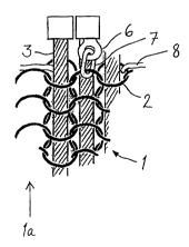
10 row the rings are inclined mainly parallelly to each other to a certain
acute angle with the main plane, and in the adjacent row the rings are
inclined with regard to the main plane of the layer 1 to an angle of
ap~JIu~ lldlèly the same ",ay, ~ ule but to an opposite direction. Every
two adjacent ring rows 1a are com~e~ d in such a fashion that two
15 successive rings 2 of one row 1a are i, ~ ~e~,ted by a common ring 2 of
the adjacent row 1a, which ring is thus inclined with respect to the main
plain of the layer to an acute angle having a ",ay" ~le equal to and a
direction opposite to the angles of the said two rings. The layer is in this
way formed of adjacent rows 1a, where the rings 2 of every other row
20 are sub~ldl ' 'Iy parallel. The most common material of the rings is
steel, but also titanium is possible, provided that it can be welded
sufficiently well.

The ring rows 1a constitute straight passages in the direction of the
25 main plane of the layer 1. Elongate filling elements 3 are passed
through the pass~ges. One filling element 3 extends thus through
successive rings 2 of the same row 1a so as to fill the free space
uthefwise present inside the ring. The elements 3 have limited
flexibility, bending to such an extent that in the longitudinal direction of
30 the filling elements 3 the layer pO5S~ S;~ S flexibility required by the use
of the garment. In the direction pe, I,end,~,.llar to the lo"_ ' ,al
direction of the filling elements the p~-: ' ./c Iayer 1 is more flexible,
because the adjacent ring rows 1a are able to turn in relation to each
other UI I~ . Ited by the filling elements. Hence, the most
35 advantageous orier,tdliùn of the filling elements 3 in the gamment is
vertical, the garment fitting well around a vertical body part such as
chest, abdomen and back. The ring rows exle" ,9 from above
downwards are in this case attached at their upper ends to the upper

WO 96/39881 21 ~ 6 6 0 3 r~

ends of the respective filling elements 3 using a suitable solution for
example as shown in Fig. 1 by means of a lug 6 attached to the upper
end of the element 3 and c."",e~lad to the u~,pe""oal ring 2 through a
fixing loop 7. In this way the elongate filling elements 3 at the same
5 time keep the layer sufficiently extended in vertical direction and
prevent it from slipping down. It will be sufficient to have such
dUdl,l 1111~1 Ita only in some elongate filling elements 3 at certain
intervals. Co, I ~po n l,Jly the lower ends of the elongate elements can
be equipped with similar dlld~ ta to prevent the layer 1 from
10 slipping towards the middle in opposite direction for example in the
event that the garrnent is le,,,po,c.,i'y positioned upside down during
storage.

Fig. 1 further shows how the layer 1 can be attached to backing
15 material for example by means of a yam 8 which passes at certain
intervals along the width through the rings 2 at the upper ends of the
ring rows 1a. The layer 1 can be attached in the same way along its
side edge and lower edge to the backing material to be deO~,ibed
h~l~ ;.,L Q';)V/,
Fig. 2 shows the structure of the fllling element 3 in more detail. The
elongate element 3 has sufficient width in the direction oF the plane of
the layer 1 so as to fill well the inner space of the ring 2. The ratio of
this Width to the inner diameter of the ring is prc~ ly such that (D-d)/2
25 is not higher than 3 mm f~ ,F~.,dLI~/ not higher than 2 5 mm and most
plc:r~ ly not higherthan 2 mm D ,~ se,lti"g in the equation the ring
inner diameter in the width direction of the elongate element 3 and d the
width of the eiongate element 3. The above limit values are thus the
widths of the free spaces ,t:",- ,i"g on both sides of the element when
30 the element passes d~plo~ t~ly through the centres of the rings. As
apparent from Fig. 1 these void inner parts of the rings are partly
covered also by the material of the rings in the adjacent ring rows.

In order to provide the element 3 with sufficient width and strength
35 without need to make it too heavy it is most p, ~re, dbly manufactured of
a col,lpol1ellt yarn having a metal outer sheath 3b ~r.;;l,ald".l",g well
impacts and a core 3a of a material lighter than the outer sheath. The
core can be for example a yam manufactured of synthetic polymer

21 96~
WO 96/39881 PU l ~r l . _
~ 5
fibre, natural fibre, ceramic fibre, or metal fibre lighter than the outer
sheath. Metal filaments have been multiplied, doubled, double-doubled
or braided around the core to fomm the outer layer 3b, resulting in a
metal wire rope which is light enough, but strong and rigid. The metal
can consist of for example steel, titanium or aluminium filaments,
including alloys and co, u b;~ ldlion:~ of different filaments.

Further, a metal core and plastic coating can be used in the co",pol1e"l
yarn, or glass, carbon or metal fibre or some con,l,;l Idliol) thereof as the
core yam and over it a plastic coating made by pultrusion can also be
used. Also such COIllLli~ldtiOn is possible that the metal core is
surrounded by a surface layer of natural fibre.

It is apparent that the filling elements can be entirely of the same
fibrous material, and for the sake of rigidity filaments of metal, such as
steel, titanium, aluminium or some alloy thereof are most suitable.
These filaments have been multiplied, doubled, double-doubled or
braided to form a yam.

In the upper portion of Fig. 2 there is shown a filling element 3 having
an advantageous cross-section. The ~ "el1sion of the cross-section of
the filling element in the direction of the plane of the layer 1 is greater
than in the direction pr,l enui~ lar to the plane. An element of this
shape, being wide in the direction of the plane fills well the inner parts
of the rings, which are oval when seen in the direction of the plane. The
"flat" yarn construction of this kind can be manufactured for example by
braiding.

Re~d" -ss of the structure or shape of the filling elements 3, they
should have sufficient stiffness to maintain their position blocking the
sharp object to prevent its pe"el,dtion. It can be surposed that the
elastic modulus co"~lalc:s well with these p,upe,lies related to
r stiffness, and filling elements with modulus of elasticity not less than 40
kN/mm2 are (eco"""e"dable.
J 35

WO96/39881 21 96603 r~llr~ -~

Fig. 3 shows one example of the p,- ~c garment acco,d ,9 to the
invention in lon_ ~ " Idl section taken vertically, that is, parallelly to the
direction of the filling elements 3. The p~ c layer 1 is situated
within the garrnent, a layer 4 made of ballistic fabric for p,uleulion
5 against bullets being placed on the outer side thereof. A woven fabric is
p,éréldLly used in this location, because when one hits with a spike-
shaped object on the side of this layer 4, fibres become detached from
the fabric and as they travel together with the object they fill more the
void space between the rings 2 and the element 3 in the protective
10 layer 1. The layer 4 can be made of any known ballistic fibre material
having p, upe, iie5 that allow to absorb energy of p, uje~liies, for example
aramid fibre, VECTRAN fibre (fully aromatic polyester, HBA-HNA
copolyrner) or PE-fibre (UHMPE, very large-molecular polyethylene).
On the inner side of the p,l ~/c layer 1, that is, towards the body,
15 there is a relatively thick porous insulation layer 5, which can be for
example foamed plastic. The purpose of the layer is to increase the
distance of the front surface of the impact-receiving layer 1 from the
body and also to increase the cu,,,'~.' b"~y to the wearer. The
insulating layer 5 acts also as the backing material, to which the
20 protective layer 1 can be attached in the above-des-,,il,ed manner by
sowing with the yam. A p,.: ~c ganment equipped with a ballistic
fabric and a layer 1 p,~ " ,9 against impacts operates well as a
protective garment against both "fast" impacts (bullets) and "slow"
impacts (edged weapons). A ballistic fabric can be placed also on the
25 inner side of the layer 1 to afford even more effective p~ule-,lion against
bullets.

In the total thickness of the protective gamment the protective layer 1 is
located clearly near the outer side and spaced from the middle plane,
30 that is, it is shifted towards the direction where the impacts that it is
arranged to stop will come from. The thick insulation layer 5 on the
inner side is capable of colll~J,essillg and it will damp the impact
energy. The protective garment is further coated on its outer and inner 'r
surface with a suitable surface layer 9 which forms a sort of bag around
35 the protective layer 1 and protects the layers 4, 5 ~ell, IM9 inside
against wear.

W096/39881 2~ 9~6~ r~llrl ~l~
~ 7
A garment acco,l ,g to the invention is for example a p~ut~uli~u vest 10
which can protect the body in the area of the chest or both the chest
and back and which has a construction known as such. It is, however,
possible to apply the solution of the invention also to coats and other
5 garments. It is also possible that the protective layer 1 can be located
only in one area of the ganment, for example to protect the most
imporLant body parts.

In one practical ,. ' ~, the protective layer 1 was manufactured
10 from a metal ring net which consisted of wires having the thickness of
ca. 0,8 mm. The wires had been welded end-to-end to fonm rings
having the inner diameter of ca. 5,5 mm. Through ring rows consi .Li"g
of the rings were threaded straight steel wire ropes of the thickness of
ca. 2 mm, the cores of which were cotton yarn. In impact tests made in
acco,-ld"ce with European Standard EN 412:1993 (width of the spike 3
mm, weight of the falling body together with the blade 1035 9) it was
found that the layer prevented effectively the pen eLI dLiOn of sharp spike-
shaped objects to such depths where they would present danger to the
wearer of the protective garment. When a ballistic fabric made of
20 aramid fibre was used in front of the layer 1, a p~uleulidn was achieved
against nickel jacket bullets shot with a 9 mm handgun at a distance of
4m.

The invention is not restricted above only to the construction shown in
25 the figures, but it can be modified within the inventional idea plt:sel ' -I
by the claims. Filling elements 3 can be used also in conjunction with
ring nets of another construction to fill vacant spaces inside the rings for
serving the purpose of the invention. Moreover, the invention is not
restricted only to the above-r"t:"lioned manufacturing materials, but
30 materials not ",e,ltidned or not yet known which give advantageous
~luleulidn ~,,upe,lies can be used therein.

Representative Drawing
A single figure which represents the drawing illustrating the invention.
Administrative Status

For a clearer understanding of the status of the application/patent presented on this page, the site Disclaimer , as well as the definitions for Patent , Administrative Status , Maintenance Fee  and Payment History  should be consulted.

Administrative Status

Title Date
Forecasted Issue Date Unavailable
(86) PCT Filing Date 1996-06-06
(87) PCT Publication Date 1996-12-19
(85) National Entry 1997-01-31
Dead Application 2004-06-07

Abandonment History

Abandonment Date Reason Reinstatement Date
2003-06-06 FAILURE TO PAY APPLICATION MAINTENANCE FEE
2003-06-06 FAILURE TO REQUEST EXAMINATION

Payment History

Fee Type Anniversary Year Due Date Amount Paid Paid Date
Application Fee $0.00 1997-01-31
Registration of a document - section 124 $0.00 1997-04-10
Maintenance Fee - Application - New Act 2 1998-06-08 $100.00 1998-05-28
Maintenance Fee - Application - New Act 3 1999-06-07 $100.00 1999-05-26
Maintenance Fee - Application - New Act 4 2000-06-06 $100.00 2000-05-24
Maintenance Fee - Application - New Act 5 2001-06-06 $150.00 2001-06-06
Maintenance Fee - Application - New Act 6 2002-06-06 $150.00 2002-05-21
Owners on Record

Note: Records showing the ownership history in alphabetical order.

Current Owners on Record
VALTION TEKNILLINEN TUTKIMUSKESKUS
Past Owners on Record
HONKALA, MARKKU
Past Owners that do not appear in the "Owners on Record" listing will appear in other documentation within the application.
Documents

To view selected files, please enter reCAPTCHA code :


To view images, click a link in the Document Description column. To download the documents, select one or more checkboxes in the first column and then click the "Download Selected in PDF format (Zip Archive)" or the "Download Selected as Single PDF" button.

List of published and non-published patent-specific documents on the CPD .

If you have any difficulty accessing content, you can call the Client Service Centre at 1-866-997-1936 or send them an e-mail at CIPO Client Service Centre.


Document
Description 
Date
(yyyy-mm-dd) 
Number of pages   Size of Image (KB) 
Claims 1996-12-19 2 41
Drawings 1996-12-19 1 16
Description 1996-12-19 7 278
Representative Drawing 1997-06-11 1 6
Cover Page 1997-05-15 1 11
Abstract 1996-12-19 1 32
Cover Page 1998-06-04 1 11