Note: Descriptions are shown in the official language in which they were submitted.
21 9672~
BACKGROUND OF THE INVENTION
The present invention relates to a bill handling machine and, in
particular, to a bill handling machine provided with a bill stacking device which
can stack bills whose sizes differ greatly in a desired manner.
DESCRIPTION OF THE PRIOR ART
A bill handling machine such as a bill receiving machine is normally
provided with a bill stacking device for stacking received bills in such a manner
that one end portions thereof are aligned.
Japanese Utility Model Application Laid Open No. 51-4074 discloses
a bill stacking device provided with a movable guide member which can abut
against the leading edge portions of bills held in a bill transport passage and
a free end portion thereof is deformed by the bills when it comes into abutment
against the bills, and when the rear end portions of the bills are fed into the bill
stacking section, it presses the bills by its returning force, thereby guiding the
bills into the bill stacking section.
Bills, such as Japanese bills, whose sizes do not differ so greatly can
be stacked in a bill stacking device by providing such a guide member so that
one end portions of the bills are aligned, either in the case of transporting them
20 SO that the shorter edges thereof are aligned with the bill transport direction or
in the case of transporting them so that the longer edges thereof are aligned
with the bill transport direction.
To the contrary, in the case where bills whose sizes differ greatly, such
as bills in European countries which range in size from 181 mm X 85 mm to
120 mm X 61.5 mm, are transported so that the shorter edges thereof are
21 96725
aligned with the bill transport direction, since the widths thereof in the direction
perpendicular to the bill transport direction range from 120 mm to 181 mm, it
is difficult to transport bills of smaller size along a desired path for discriminating
them. Therefore, bill handling machines which transport bills so that the longeredges thereof are aligned with the bill transport direction are generally used in
European countries.
Although bills transported so that the longer edges thereof are aligned
with the bill transport direction can be discriminated in a desired manner, it is
difficult in this case to stack bills of smaller size in a single bill stacking device
so that one end portions thereof are aligned. As a result, one bill stacking device
has to be provided for each denomination of bills, whereby the structure o~ the
bill handling machine becomes inevitably complicated and the size thereof
becomes large.
Further, it is preferable for a bill handling machine to be able to use
received bills for dispensation. However, if bills of different denominations
cannot be stacked in a single bill stacking device so that one end portions are
aligned, it is impossible to take out bills stacked in the bill stacking device,store them in accordance with their denominations and use received bills for
dispensation.
SUMM~RY OF THE INVENTION
It is therefore an object of the present invention to provide a bill
handling machine provided with a bill stacking device which can stack bills
whose lengths in the bill transport direction differ greatly so that one end
portions thereof are aligned.
2 1 ~ 67~5
The above and other objects of the present invention can be
accomplished by a bill handling machine provided with a bill stacking device
comprising a bill press member whose leading end portion is swingably
supported and which is adapted to guide bills downwardly, bill press member
5driving means for pressing the leading end portion of the bill press member
downwardly, sensor means for detecting rear end portions of bills to be
stacked, and control means for actuating, based on a detection signal, the bill
press member driving means when a predetermined time period has passed
after the sensor means detected the rear end portion of the bill.
The above and other objects of the present invention can be also
accomplished by a bill handling machine provided with a bill stacking device
comprising a bill press member whose leading end portion is swingably
supported and which is adapted to guide bills downwardly, biasing means for
biasing the leading end portion of the bill press member upwardly, bill press
15member driving means for pressing the leading end portion of the bill press
member downwardly against a biasing force of the biasing means, sensor means
for detecting rear end portions of bills to be stacked, and control means for
actuating, based on a detection signal, the bill press member driving means
when a predetermined time period has passed after the sensor means
23detected the rear end portion of the bill, the bill stacking device being mounted
on a machine body so that a downstream portion thereof is located at a higher
position than a upstream portion thereof with respect to a bill feeding direction.
Further, the above and other objects of the present invention can be
accomplished by a bill handling machine provided with a bill stacking device
25comprising a bill press member whose leading end portion is swingably
21 96~25
supported and which is adapted to guide bills downwardly, biasing means for
biasing the leading end portion of the bill press member upwardly, a bill stack
member for stacking bills on an upper surface thereof, swinging means for
swinging, when stacking bills, the bill press member about an upper side end
portion with respect to a bill feeding direction so that a downstream portion
thereof is located at a higher position than a upstream portion thereof, a bill
press member driving means for pressing the leading end portion of the bill
press member downwardly against a biasing force of the biasing means,
sensor means for detecting rear end portions of bills to be stacked, and controlo means for actuating, based on a detection signal, the bill press member driving
means when a predetermined time period has passed after the sensor means
detected the rear end portion of the bill.
In a preferred aspect of the present invention, the bill stacking device
further comprises a vane wheel for scraping off rear end portions of bills.
In a further preferred aspect of the present invention, the bill press
member driving means is constituted by a solenoid.
In a further preferred aspect of the present invention, the bill stacking
device further comprises fixed endless drive belt means and endless driven
belt means which can be moved with respect to the endless drive belt means
and hold bills between itself and the endless drive belt means.
In a further preferred aspect of the present invention, the bill press
member is movable together with the endless driven belt means.
In a further preferred aspect of the present invention, the biasing means
is constituted by a spring.
In a further preferred aspect of the present invention, the upstream side
21 q61~5
end portion of the bill stack member is swingably mounted on an upstream side
wall portion of the bill stacking device.
The above and other objects and features of the present invention will
become apparent from the following description made with reference to the
accompanying drawings.
BRIEF DESCRIPTION OF THE DRAWINGS
Figure 1 is a schematic longitudinal cross sectional view of a bill
receiving machine which is an embodiment of the present invention.
Figure 2 is a schematic longitudinal cross sectional view showing the
details of a transaction opening and a drum shown in Figure 1.
Figure 3 is a schematic front view of a shutter.
Figure 4 is a schematic left side view of a drum of a bill receiving
machine.
Figure 5 is a schematic right side view of a drum of a bill receiving
machine.
Figure 6 is a schematic side view showing the structure of a first bill
stacking device.
Figure 7 is a schematic rear view of Figure 6.
Figure 8 is a schematic side view showing a first bill stacking device in
which stacked bills are held between a pair of endless driven belts and a pair
of endless drive belts.
Figure 9 is a schematic side view showing a bill stacking device of a
safe in which the leading end portion of a bill has just been fed into the safe.
Figure 10 is a schematic side view showing a bill stacking device of a
2~ q 67 25
safe in which the leading end portion of a bill has been fed into the safe and
the bill is led along the lower surface of a bill press plate.
Figure 11 is a schematic side view showing a bill stacking device of a
safe in which a bill has been further fed into the safe and the rear end portionof the bill is detected by a sensor.
Figure 12 is a schematic side view of a bill stacking device of a safe
showing the leading end portion of a bill press plate pressed toward a bill
stacking plate by driving a solenoid, thereby stopping a bill fed into the safe so
that the rear end portion of the bill can be scraped off downwardly by a vane
wheel.
Figure 13 is a schematic side view of a bill receiving section.
Figure 14 is a schematic plan view of a bill receiving section.
Figure 15 is a schematic front view of a bill receiving section.
Figure 16 is a schematic cross sectional view taken along line A-A in
Figure 15.
Figure 17 is a schematic side view of a bill taking out device for taking
out bills.
Figure 18 is a block diagram of a drive system and a control system of
a bill receiving machine which is an embodiment of the present invention.
Figure 19 is a block diagram of a detecting system and a control
system of a bill receiving machine which is an embodiment of the present
invention.
Figure 20 is a schematic cross sectional view taken along line A-A in
Figure 15 with a motor stopped.
Figure 21 is a schematic side view showing the structure of a first bill
2 1 96 1 25
stacking device of a bill handling machine which is another embodiment of the
present invention.
Figure 22 is a schematic side view showing the structure of a second
bill stacking device 80 of a bill handling machine which is a further embodimentof the present invention.
Figure 23 is a schematic side view showing a second bill stacking
device into which the leading end portion of a bill has just been fed.
Figure 24 is a schematic side view showing the second bill stacking
device when the rear end portion of a bill is detected by the sensor.
Figure 25 is a schematic side view showing the second bill stacking
device when the leading end portion of a bill is pressed by the leading portion
of a bill press plate.
Figure 26 is a schematic side view showing the second bill stacking
device when the driving of a solenoid is stopped and the leading end portion
of a bill press plate is being moved upwardly by a torsion spring.
DESCRIPTION OF THE PREFERRED EMBODIMENT
As shown in Figure 1, a bill receiving machine includes a transaction
opening 1 used for receiving bills and returning unacceptable bills and the
transaction opening 1 is connected to the inside of the bill receiving machine
via a shutter 2. A bill placement base 3 is provided in the transaction opening
1 and bills are placed on the bill placement base 3 to be received by the bill
receiving machine and unacceptable bills are placed on the bill placement base
3 to be returned.
A hollow rotatable drum 4 is provided at a position adjacent to the
2~ 961~5
shutter 2 in the bill receiving machine. In the drum 4, a pair of endless drive
belts 5 and a pair of endless driven belts 6 are provided so as to face each
other and the pair of endless driven belts 6 are movable with respect to the pair
of endless drive belts 5. Figure 1 shows only one of the pair of endless drive
belts 5 and one of the pair of endless driven belts 6. A first shutter 7 and a
second shutter 8 are provided at opposite end portions of a bill transport
passage formed by the endless drive belts 5 and the endless driven belts 6 for
opening and closing the bill transport passage and a third shutter 9 is providedat a substantially central portion of the bill transport passage formed by the
o endless drive belts 5 and the endless driven belts 6 so as to be able to project
into and be retracted from the bill transport passage. The length of the bill
transport passage formed by the endless drive belts 5 and the endless driven
belts 6 is determined to be slightly greater than the length of the longer edge
of the bill whose longer edge is greatest among bills to be handled and the
length between the end portion of the bill placement base 3 in the transaction
opening 1 on the side opposite from the drum 4 and the central portion into
which the third shutter 9 projects is also determined to be slightly greater than
the length of the longer edge of the bill whose longer edge is greatest among
bills to be handled. Further, the length between the end portion of the bill
placement base 3 in the transaction opening 1 on the side opposite from the
drum 4 and the end portion of the bill transport passage formed by the endless
drive belts 5 and the endless driven belts 6 on the side of the transaction
opening 1 and the length between the end portion of the bill placement base
3 on the side of the drum 4 and the third shutter 9 are determined to be shorter
than the length of the longer edge of bill whose longer edge is shortest among
2 ~ 7 2 5
bills to be handled. Bills are deposited into the transaction opening 1, while the
shutter 2 and the first shutter 7 of the drum 4 facing the transaction opening 1are opened and the third shutter 9 is kept projecting into the bill transport
passage. Therefore, bills whose longer edges are greatest among bills to be
handled are accommodated between the end portion of the bill placement base
3 on the side opposite from the drum 4 and the third shutter 9 to substantially
abut against the third shutter 9 and that bills whose longer edges are shortest
are accommodated between the end portion of the bill placement base 3 on the
side opposite from the drum 4 and the third shutter 9 in such a manner that
parts thereof are placed on the endless drive belts 5. As a result, after the third
shutter 9 has been retracted from the bill transport passage and the endless
driven belts 6 are lowered, bills deposited into the transaction opening 1 can
be held between the endless drive belts 5 and the endless driven belts 6 and
reliably taken into the drum 4 by driving the endless drive belts 5. The drum 4
iS rotatable by a motor (not shown) mounted on the body of the bill receiving
machlne.
A bill receiving section 10 is provided immediately below the drum 4.
The bill receiving section 10 comprises a pair of fixed endless drive belts 11,
a pair of endless driven belts 12 movable between a holding position where
bills are held between the endless drive belts 11 and themselves and a
retracted position where bills are released, a bill press plate 13 supported
integrally with the endless driven belts 12 and movable in parallel to the surface
of the endless driven belts 12 on the side of the endless drive belts 11, a lower
end plate 14 forming the lower portion of the bill receiving section 10, a shutter
15 capable of opening and closing a portion between the endless drive belts
2~ q 61 25
1 1 and the lower end plate 14, a take-out roller 16 provided in the vicinity of the
lower end plate 14 and the lower portion of the shutter 15 for taking out bills
from the bill receiving section 10, and a separation roller 17 for ensuring thatbills are taken out one by one by the take-out roller 16. Figure 1 shows only
one of the pair of endless drive belts 11 and one of the pair of endless driven
belts 12. The endless drive belts 1 1 are disposed so that the surfaces thereof
on the side of the endless driven belts 12 are flush with the surfaces of the
corresponding endless drive belts 5 when the drum 4 is rotated
counterclockwise from the position shown in Figure 1 by 90 degrees.
o When bills taken into the drum 4 and held between the endless drive
belts 5 and the endless driven belts 6 are to be fed to the bill receiving section
10, the drum 4 is rotated counterclockwise from the position shown in Figure
1 by 90 degrees and the endless drive belts 5 and the endless drive belts 11
are driven. As a result, the bills are fed into the space between the endless
drive belts 11 and the endless driven belts 12 and held therebetween. Further,
the bills are fed into the bill receiving section 10 by driving the endless drive
belts 11. Then, the endless driven belts 12 are retracted to the retracted position
and the bills are stored in the bill receiving section 10 as supported by the
endless drive belts 11, the bill press plate 13 and the lower end plate 14.
A first bill transporting section 23 is connected to the downstream side
of the take-out roller 16 of the bill receiving section 10. Bills received in the bill
receiving section 10 are taken out one by one by the take-out roller 16 and the
separation roller 17 and after the number of bills has been counted by a sensor
(not shown) provided immediately downstream of the take-out roller 16, they
are fed to the first bill transporting section 23.
1 1
2~ 9672~
The first bill transporting section 23 is constituted so as to transport a
bill toward the rear side of the bill receiving machine, while simultaneously
correcting the orientation of the bill if its longer edge form an angle with the bill
transporting direction so that the longer edge of the bill is aligned with the bill
transporting direction.
A second bill transporting section 25 extending upwardly is provided at
the terminal end portion of the first bill transporting section 23. A bill is
delivered from the first bill transporting section 23 to the second bill
transporting section 25 and transported upwardly and then toward the front
side of the bill receiving machine.
A bill discriminating section 24 is provided at the beginning end portion
of the second bill transporting section 25 for discriminating whether or not bills
are acceptable and the denomination of the bills which are acceptable. A first
gate member 26 is provided at the terminal end portion of the second bill
transporting section 25. A bill discriminated to be unacceptable by the bill
discriminating section 24 is fed to a first bill stacking device 30 by the first gate
member 26. On the other hand, a bill discriminated to be acceptable is
delivered to a third bill transporting section 27 connected to the terminal end
portion of the second bill transporting section 25 and is transported upwardly.
It is then stacked in a second bill stacking device 80 by a second gate member
28.
The first bill stacking device 30 is disposed behind and below the drum
4 in such a manner that its longitudinal direction forms an angle of 45 degrees
with the horizon and the second bill stacking device 80 is disposed behind the
drum 4 in such a manner that its longitudinal direction is substantially horizontal.
12
21 't6725
The first bill stacking device 30 and the second bill stacking device 80 have the
same structure. The first bill stacking device 30 communicates with the drum
4 so as to be able to deliver bills to the drum 4 when the drum 4 is rotated
clockwise from the position shown in Figure 1 by about 45 degrees and the
second bill stacking device 80 communicates with the drum 4 so as to be able
to deliver bills to the drum 4 when the drum 4 is located at the position shown
in Figure 1.
The bill receiving machine further comprises an unacceptable bill
collecting section 29 located on the front side of the bill receiving section 10 for
collecting any bill discriminated to be unacceptable by the bill discriminating
section 24 and not accepted by the customer although once returned to the
customer, and a safe 90 located on the rear side of the bill receiving machine
for storing received and acceptable bills.
When all received bills have been fed out from the bill receiving section
10, unacceptable bills stacked in the first bill stacking section 30 are fed to the
drum 4 and returned to the transaction opening 1. Unacceptable bills returned
to the transaction opening 1, but not accepted by the customer, are again fed
to the drum 4 and collected in the unacceptable bill collecting section 29.
The total value of the deposited bills is displayed on a display means
(not shown) based on the discrimination made by the bill discriminating section
24. When the customer confirms the amount of deposited bills and instructs the
machine to receive the bills, the acceptable bills stacked in the second bill
stacking device 80 are fed to the drum 4 and further fed to the third bill
transporting section 27 via the bill receiving section 10, the first bill transporting
section 23, the bill discriminating section 24 and the second bill transporting
13
~6125
section 25. Then, they are stored in the safe 90 by the second gate member
28.
Figure 2 is a schematic longitudinal cross sectional view showing the
details of the transaction opening and the drum shown in Figure 1.
As shown in Figure 2, a motor 100 is provided above the shutter 2 and
the drum 4 for opening and closing the shutter 2. An arm 102 is fixed to the
output shaft 1 OOa of the motor 100 and a roller 101 is rotatably mounted on thetip end portion of the arm 102. The roller 101 abuts against the lower surface
of a bent portion 2a of the shutter 2 extending from the upper portion of the
o shutter 2 toward the drum 4 in substantially the horizontal direction and
supports it. Therefore, when the motor 100 is driven and the arm 102 is swung
counterclockwise in Figure 2, the roller 101 mounted on the tip end portion of
the arm 102 is lowered along an arcuate path and, therefore, the bent portion
2a of the shutter 2 is lowered, whereby the shutter 2 is moved from the open
position shown in Figure 2 to a closed position where it shuts off the
communication between the transaction opening 1 and the inside of the bill
.
recelvlng machlne.
Figure 3 is a schematic front view of the shutter 2.
As shown in Figure 3, the lower edge of the shutter 2 is formed with a
plurality of projections 2b projecting downwardly at substantially regular
intervals. The end portion of the bill placement base 3 on the side of the drum
4 is formed with concave portions 3b whose size and shape are
complementary to the projections 2b of the shutter 2. The projections 2b can
therefore engage with the concave portions 3b unless one or more bills remain
between the shutter 2 and the bill placement base 3, in which case the
14
21 9 6725
projections 2b and the concave portions 3b do not completely engage with each
other and the shutter 2 cannot be closed. As a consequence, it is possible to
detect whether or not bills remain between the shutter 2 and the bill placement
base 3 by detecting whether or not the shutter 2 is closed.
As shown in Figure 2, the endless drive belts 5 fixed to the drum 4 are
wound around rollers 103, 104, 105 and a bill guide 106 is mounted on the
drum 4 slightly below the surface of the endless drive belts 5 on the side of the
endless driven belts 6.
Further, the movable endless driven belts 6 are wound around rollers
108, 109, 110 and the rollers 108, 109, 110 are rotatably mounted on a
connecting member 107 mounted on the drum 4 to be movable in the direction
perpendicular to the bill transporting direction. A bill guide 111 is mounted onthe side of the endless drive belts 5 to be movable in the direction perpendicular
to the surface of the endless driven belts 6. When the endless driven belts 6
are moved apart from the endless drive belts 5, the bill guide 111 engages with
a stopper (not shown) and is located at a position closer to the endless drive
belts 5 than the surface of the endless driven belts 6 on the side of the endless
drive belts 5. On the other hand, when the endless driven belts 6 are moved
close to the endless drive belts 5 so as to be able to hold bills between the
endless drive belts 5 and themselves, the bill guide 111 is retracted to a
position more apart from the endless drive belts 5 than the surfaces of the
endless driven belts 6 on the side of the endless drive belts 5, thereby
preventing the bill guide 111 from influencing the bill holding and the bill
transportation.
As shown in Figure 2, the first shutter 7 provided at one end portion of
2~ 967~5
the bill transport passage formed by the endless drive belts 5 and the endless
driven belts 6 comprises an upper shutter member 7a and a lower shutter
member 7b and the second shutter 8 provided the other end portion of the bill
transport passage comprises an upper shutter member 8a and a lower shutter
member 8b. The first shutter 7 and the second shutter 8 are closed or opened
by moving the upper shutter members 7a, 8a and the lower shutter members
7b, 8b so as to be close to or apart from each other.
Further, the lower end portion of the third shutter 9 which can project
into or be retracted from the bill transport passage formed by the endless drivebelts 5 and the endless driven belts 6 at substantially the central portion thereof
is connected to the tip end portion of a swing arm 114 swingable about a shaft
1 13 by a solenoid 1 12 in Figure 2. The third shutter 9 can be projected into the
bill transport passage between the pair of endless drive belts 5 by actuating the
solenoid 112 and swinging the swing arm 114 about the shaft 113 from a
retracted position indicated by a broken line in Figure 2 to a projected position
indicated by a solid line in Figure 2.
Figure 4 is a schematic left side view of the drum 4 of the bill receiving
machine.
As shown in Figure 4, roller shafts 1 08a, 1 1 Oa of the rollers 108, 1 10
among the three rollers 108, 109, 1 10 around which the endless driven belts
6 are wound project the outside of the drum 4 through a pair of elongate slots
11 5a, 11 5a formed on the left side plate 115 of the drum 4 with respect to thebill transporting direction to extend in the direction perpendicular to the billtransport passage and are connected to a pair of blocks 1 17, 117 movable
along a pair of slide rails 116, 116 in the direction perpendicular to the bill
16
21 96-/25
transport passage. The pair of blocks 117, 117 are connected to the opposite
end portions of a connecting plate 118. In Figure 4, the opposite end portions
of a spring 120 provided along the lower sides of a pair of pulleys 119, 1 19 are
connected to the lower edge portions at the opposite end portions of the
connecting plate 118, whereby the connecting plate 118 is biased downwardly.
As shown in Figure 4, a substantially L-shaped release arm 121 is
mounted on the drum 4 to be movable in the direction perpendicular to the bill
transport passage. When the release arm 121 is moved upwardly in Figure 4,
the upper side surface of a bent portion 121 a extending from the lower end
portion of the release arm 121 in substantially the horizontal direction engageswith the lower edge portion at the center portion of the connecting plate 118,
whereby the connecting plate 118 is moved upwardly against the spring force
of the spring 120. The upper end portion of the release arm 121 in Figure 4 is
connected to a swing arm 123 fixed to the output shaft 1 22a of a motor 122
mounted on the side plate 1 15 of the drum 4 and is movable upwardly in Figure
4 by rotating the motor 122.
Further, as shown in Figure 4, a pulley 124 is fixed to the side plate 115
of the drum 4 and a belt 127 is wound around the pulley 124 and a pulley 125
fixed to the output shaft 1 26a of a motor 126 mounted on the body of the bill
receiving machine. The drum 4 is rotatable about a center shaft 4a thereof by
driving the motor 126. In this embodiment, the motor 126 can be repeatedly
rotated little by little in both forward and reverse directions by a later mentioned
CPU (not shown).
Figure 5 is a schematic right side view of the drum 4 of the bill receiving
machine.
17
21 q6725
As shown in Figure 5, roller shafts 103a,105a of the rollers 103,105
among the three rollers 103,104,105 around which the endless drive belts 5
are wound project the outside of the drum 4 through the right side plate 128 of
the drum 4 and pulleys 129,130 are mounted on the projecting roller shafts
103a,105a. A driven pulley 132 mounted on the output shaft 131 a of a motor
131 for driving the endless drive belts 5 and a driven pulley 133 are mounted
on the side plate 128. A belt 134 is wound around the pulleys 129,130,132,
133 and driving force of the motor 131 is transmitted to the endless drive belts5 via the pulleys 129,130 and rollers 103,105.
Further, as shown in Figure 5, the upper shutter member 7a and the
lower shutter member 7b constituting the first shutter 7 are mounted on the
drum 4 so as to be swingable about pins 135a,135b extending in the direction
perpendicular to the bill transporting direction between a closed position wherethey close the bill transport passage and a open position where they open the
bill transport passage. In Figure 5, the portion of the upper shutter member 7a
below the pin 135a is formed with an elongate slot 136a extending in the
direction perpendicular to the bill transportation direction and the lower shutter
member 7b above the pin 135b is formed with an elongate slot 136b extending
in the direction perpendicular to the bill transportation direction. Pins 137a,137b
formed on a slide plate 137 movably mounted on the drum 4 in the bill
transporting direction penetrate through the elongate slots 136a,136b. One
end portions of a pair of springs 138,138 are connected to the end portion of
the slide plate 137 closer to the second shutter 8. The slide plate 137 is biased
by the pair of springs 138,138 toward the second shutter 8 to hold the upper
shutter member 7a and the lower shutter member 7b via the pins 137a,137b
18
21 96725
at the closed position as shown in Figure 5.
Furthermore, a pin 141 provided at the tip end portion of a drive arm 140
mounted on the drum 4 to be swingable about a shaft 139 engages with the end
portion of the slide plate 137 closer to the second shutter 8. The tip end portion
of the plunger 142a of a solenoid 142 is connected to the drive arm 140
between the shaft 139 and the pin 141. Therefore, when the solenoid 142 is
actuated and the plunger 142a is retracted, the drive arm 140 is swung
clockwise in Figure 5 about the shaft 139 and the slide plate 137 is moved
toward the first shutter 7 against the spring force of the springs 138,138. As
o a result, the upper shutter member 7a and the lower shutter member 7b are
swung about the pins 135a,135b via the pins 137a,137b and are moved from
the closed position indicated by a broken line in Figure 5 to the open position.As shown in Figure 5, the upper shutter member 8a and the lower
shutter member 8b constituting the second shutter 8 are mounted on the drum
4 so as to be swingable about pins 143a, 143b extending in the direction
perpendicular to the bill transportation direction between a closed position
where they close the bill transport passage and a open position where they
open the bill transport passage. In Figure 5, the portion of the upper shutter
member 8a below the pin 143a is formed with an elongate slot 144a extending
in the direction perpendicular to the bill transportation direction and the portion
of the lower shutter member 8b above the pin 143b is formed with an elongate
slot 144b extending in the direction perpendicular to the bill transportation
direction. Pins 145a,145b formed on a slide plate 145 movably mounted in the
bill transporting direction on the drum 4 penetrate through the elongate slots
144a, 144b. The other end portions of the pair of springs 138, 138 one end
19
21 967~5
portions of which are connected on the slide plate 137 are connected to the
end portion of the slide plate 145 closer to the first shutter 7. The slide plate
145 is biased by the pair of springs 138,138 toward the first shutter 7 to hold
the upper shutter member 8a and the lower shutter member 8b via the pins
144a,144b at a closed position as shown in Figure 5.
Further, a pin 148 provided at the tip end portion of a drive arm 147
mounted on the drum 4 to be swingable about a shaft 146 engages with the end
portion of the slide plate 145 closer to the first shutter 7. The tip end portion of
a plunger 149a of a solenoid 149 is connected to the drive arm 147 between
the shaft 146 and the pin 148. Therefore, when the solenoid 149 is actuated
and the plunger 149a is retracted, the drive arm 147 is swung counterclockwise
in Figure 5 about the shaft 146 and the slide plate 145 is moved toward the
second shutter 8 against the spring force of the springs 138,138. As a result,
the upper shutter member 8a and the lower shutter member 8b are swung
about the pins 143a,143b via the pins 145a,145b and are moved from the
closed position indicated by a broken line in Figure 5 to the open position.
Figure 6 is a schematic side view showing the structure of the first bill
stacking device 30.
As shown in Figure 6, the first bill stacking device 30 comprises a vane
wheel 32 below a roller pair 31 located adjacent to the first gate member 26
shown in Figure 1, a pair of fixed endless drive belts 33 below the vane wheel
32 and a pair of movable endless driven belts 34 above the vane wheel 32. A
bill press plate 35 for pressing stacked bills is swingably mounted on a supportshaft 36. In Figure 6, among the pair of endless drive belts 33 and the pair of
the endless driven belts 34, only one of them is respectively shown. A group
21 ~ 67~5
of rollers 37 and the support shaft 36 are supported by a mounting unit 38. A
sensor 39 for detecting the rear end portion of a bill is provided on the side of
the vane wheel 32 nearer the first gate member 26. The center portion of a unit
side plate 40 to which the endless drive belts 33 are fixed is formed with an
opening 41 extending perpendicularly to the endless drive belts 33, and a rollershaft 42 fixed to the mounting unit 38 for rotatably supporting a central rolleraround which the endless driven belts 34 are wound projects to the outside of
the unit side plate 40 through the opening 41.
Figure 7 is a schematic rear view of Figure 6.
As shown in Figure 7, the roller shaft 42 for rotatably supporting the
central roller around which the endless driven belts 34 are wound among the
group of rollers 37 is fixed to a block 43 and the block 43 is supported by a
slide rail 44 extending perpendicularly to the endless drive belts 33 formed on
the unit side plate 40. The roller shaft 42 is rotatably engaged with a notched
portion 46 formed in the tip end portion of a swing arm 45 and the swing arm
45 is swingably supported by a shaft 47. One end portion of a spring 48 is
connected to the swing arm 45 and the other end portion of the spring 48 is
connected to a connecting arm 49. The connecting arm 49 is swingably
supported by the shaft 47 and is formed with a pin 50. The pin 50 is fitted intoan elongate slot 52 formed in a crank arm 51 and biased by a spring 53
downwardly in Figure 7. A cam 55 to which a motor shaft 54 is fixed is rotatablymounted on the crank arm 51.
As shown in Figures 6 and 7, the first bill stacking device 30 comprises
an upper shutter member 56a swingable upwardly about a pin 68a and a lower
shutter member 56b swingable downwardly about a pin 68b on the side
21
~ q 6-125
opposite from the vane wheel 32. The upper shutter member 56a and the lower
shutter member 56b are connected to each other by a pin 57 provided on the
lower shutter member 56b and an elongate slot 58 formed in the upper shutter
member 56a.
S The upper shutter member 56a is formed with a roller 60 projecting to
the outside through an opening 59 formed in the unit side plate 40 and the
roller 60 is engaged with a guide slot 62 formed in a guide member 61 supported
by the block 43.
In the thus constituted first bill stacking device 30, the endless driven
belts 34 can be moved with respect to the endless drive belts 33 by rotating themotor shaft 54.
More specifically, when the motor shaft 54 is rotated while the endless
driven belts 34 shown in Figures 6 and 7 are apart from the endless drive belts
33, the cam rotates a half turn, whereby the crank arm 51 is lowered. Since the
pin 50 formed on the connecting arm 49 and fitted into the elongate slot 52
formed in the crank arm 51 is biased downwardly by the spring 53, it is lowered
and the connecting arm 49 is swung downwardly. Therefore, the swing arm 45
is also swung downwardly by the spring 48 and the roller shaft 42 rotatably
engaged with the notched portion 46 formed on the tip end portion of the swing
arm 45 is lowered, whereby the mounting unit 38 is lowered and the endless
driven belts 34 mounted on the mounting unit 38 is moved close to the endless
drive belts 33.
When the endless driven belts 34 is lowered and comes into abutment
with bills stacked in the first bill stacking device 30, the lowering movement of
the mounting unit 38 is stopped and the swinging movements of the swing arm
22
~l ~6125
45 and the connecting arm 49 are also stopped. Although the crank arm 51
continues to be lowered, the movement of the pin 50 formed on the connecting
arm 49 and fitted into the elongate slot 52 formed in the crank arm 51 is
stopped. As a result, bills stacked in the first bill stacking device 30 are held
between the endless driven belts 34 and the endless drive belts 33 by the springforce of the spring 53.
Further, as shown in Figures 6 and 7, the bill press plate 35 comprises
a roller 63 projecting to the outside through an opening 64 formed in the unit
side plate 40 at a position apart from the support shaft 36 for swingably
o supporting the bill press plate 35. On the other hand, as shown in Figure 7, on
the wall portion of the unit side plate 40 on the opposite side from the endlessdrive belts 33 and the endless driven belts 34, are provided a solenoid 65, a
link 67 connected to a plunger 66 of the solenoid 65 and an actuating plate 69
one end portion of which is swingably supported by the shaft 47 formed on the
unit side plate 40, the other end portion of which is connected to the tip end
portion of the link 67 and the side surface of which abuts against the roller 63.
As shown in Figures 6 and 7, when bills are stacked in the first bill
stacking device 30, the endless driven belts 34 are kept at a position apart from
the endless drive belts 33 and at this time, the actuating plate 69 abuts against
the roller 63. After the bills have been fed into the first bill stacking device 30,
the solenoid 65 is driven at appropriate timing and the actuating plate 69
presses the roller 63 to the left in Figure 6 and to the right in Figure 7, whereby
bills are stacked by the bill press plate 35 in such a manner that the rear edges
of the bills are aligned with one of the wall portions of the first bill stacking
device 30.
23
21 ~ 6 / 2~
On the contrary, after the motor shaft 54 has been rotated, the
mounting unit 38 lowered and the bills stacked in the first bill stacking device30 held between the endless driven belts 34 and the endless drive belts 33, the
roller 63 is moved downwardly along the opening 64 formed in the unit side
plate 40 and, as shown in Figure 8, the bill press plate 35 is located above thesurface of the endless driven belts 34 on the side of the endless drive belts 33,
thereby preventing the bill press plate 35 from influencing the feed-out operation
of the bills from the first bill stacking device 30.
The first bill stacking device 30 is further provided with a bill stacking
plate 70 on the upper surface of which bills are stacked when stacking bills.
The bill stacking plate 70 is connected to a slide plate 71 engaged with the roller
shaft 42 and is movable together with the mounting unit 38 and the endless
driven belts 34. During bill stacking, therefore, the bill stacking plate 70 is located
above the upper surface of the endless drive belts 33 through the space
-, ~ between the pair of endless drive belts 33 and bills are received on the upper
surface thereof. On the other hand, when the stacked bills are held between
the endless driven belts 34 and the endless drive belts 33 for feeding out the
bills from the first bill stacking device 30, the bill stacking plate 70 is retracted
below the upper surfaces of the endless driven belts 34. Since bills are stackedon the bill stacking plate 70 in this manner, the first bill stacked is not subjected
to a frictional force from the endless drive belts 33. Therefore, it is ensured that
the first bill can be stacked in the first bill stacking device 30 in the desired
manner.
The second bill stacking device 80 has the same structure except that
it is disposed adjacent to the second gate member 28 and behind the drum 4
24
21 ~t6125
in such a manner that the longitudinal direction thereof is substantially
horizontal.
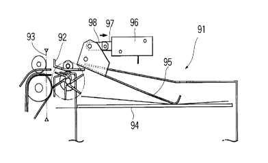
Figures 9 to 12 show the structure of the bill stacking device 91 of the
safe 90 and the process for stacking bills in the safe 90.
As shown in Figures 9 to 12, the bill stacking device 91 of the safe 90
comprises a vane wheel 92 at its entrance and a sensor 93 for detecting the
rear end portions of bills fed into the safe 90 by the vane wheel 92. Bills are
stacked on a movable bill stacking plate 94. The movable bill stacking plate 94
is movable vertically in accordance with the number of bills stacked thereon
and a bill press plate 95 is provided for pressing bills stacked on the movable
stacking plate 94. The bill press plate 95 is fixed to the tip end portion of a link
98 connected to the plunger 97 of a solenoid 96.
Figures 9, 10, 11 and 12 respectively show the state when a bill has
just been fed into the safe 90, when the leading end portion of the bill has been
fed into the safe 90 and the bill is led along the lower surface of the bill press
plate 95, when the bill has been further fed into the safe 90 and that the rear
end portion of the bill is detected by the sensor 93 and when the solenoid 96
has been driven to press the leading end portion of the bill press plate 95 toward
the bill stacking plate 94, thereby stopping the bill fed into the safe 90, and the
rear end portion of the bill has been scraped off downwardly by the vane wheel
92. More specifically, when a predetermined time period has passed after a bill
was fed into the safe 90 along the lower surface of the bill press plate 95 by the
vane wheel 92 and the rear end portion of the bill was detected by the sensor
93, the solenoid 96 is driven, thereby stopping the bill fed into the safe 90 and
the rear end portion of the bill is scraped off downwardly by the vane wheel. As
~ 96125
a result, the bills are stacked on the bill stacking plate 94 in such a manner that
the rear end portions thereof are aligned along the wall portion on the entranceside of the safe 90.
Figures 13,14,15 and 16 respectively show a schematic side view of
the bill receiving section 10, a schematic plan view thereof, a schematic front
view thereof and a schematic cross sectional view taken along line A-A in
Figure 15.
As shown in Figures 13 to 15, the bill receiving section 10 comprises
a unit side plate 150 and the pair of endless drive belts 11 are fixed to the unit
side plate 150. A bill guide 151 is mounted on the unit side plate 150 to extendvertically. The movable endless driven belts 12 are wound around rollers 154a,
154b, 154c rotatably supported by shafts 153a, 153b, 153c supported by a
support member 152. The center shaft 153b is fixed to the support member
152 and further projects to the outside of the unit side plate 150, as shown in
Figures 14 and 15. A mounting block 155 is fixed to the projecting portion of
the shaft 153b. The mounting block 155 is supported by the unit side plate 150
via a slide rail 156 that extends horizontally.
The bill press plate 13 is supported by the shaft 153a, 153c via
supporting members 157a, 157b and is biased by a spring 158 toward the
endless drive belts 11.
A solenoid 160 is supported by the shaft 153b projecting to the outside
of the unit side plate 150 and an arm 163 is swingably supported by a link 162
mounted on the plunger 161 of the solenoid 160.
One end portion of a connecting member 166 is swingably mounted on
a shaft 165 located in the vicinity of the upper end portion of the support member
26
21~ï25
152 and the other end portion of the connecting member 166 is engaged with
the bill press plate 13. A roller 167 rotatably mounted on the arm 163 is
engaged with the connecting member 166.
The bill press plate 13 is formed with a sensor actuating plate 170 and
a sensor 171 actuated by the sensor actuating plate 170 is provided on the
support member 152 for detecting the position of the bill press plate 13.
As shown in Figures 15 and 16, a cam 182 fixed to the output shaft 181
of a motor 180 is provided on the outside of the unit side plate 150 and a
sensor 183 and a sensor 184 are provided in the vicinity of the cam 182. A
o sensor actuating plate 185 is mounted on the cam 182 for actuating the sensor
183 and the sensor 184.
A swing arm 190 which supports a cam follower 186 abutting against
the cam 182 is provided in the vicinity of the cam 182. The swing arm 190 is
swingably supported by a shaft 187 via a spring 189 and swingably supported
by a shaft 187 at one end portion thereof and is connected to a drive arm 188.
The other end portion of the swing arm 190 is formed with a notched portion
191 and the shaft 153b projecting from an opening 192 formed in the unit side
plate 150 is engaged with the notched portion 191.
Further, as shown in Figure 13, a sensor 195 is provided for
discriminating whether or not a bill is present in the bill receiving section 10 and
a sensor 196 is provided for detecting whether or not any bill is present at a
lower end portion of the bill receiving section 10.
Figure 17 is a schematic side view of a bill take-out device for taking
out bills from the bill receiving section 10.
As shown in Figure 17, the bill take-out device comprises the take-out
2~ q6725
roller 16 for making contact with the leading end portions of bills and taking out
the bills, the separation roller 17 which cooperates the take-out roller 16 to
prevent two or more bills from being simultaneously taken out, a driven
transporting roller 1 8a touching the circumference of the take-out roller 16, and
a bill thickness sensor 22 comprising a reference roller 19, a driven roller 20
and a rotary encoder 21 for detecting the thickness of a bill based on the
amount of the movement of the driven roller 20 detected by the rotary encoder
21 when a bill passes through the gap between the reference roller 19 and the
driven roller 20 and outputting a detection signal.
o The take-out roller 16 has a circumferential surface formed of a high
frictional material and is formed along the shaft thereof with a large diameter
portion, a small diameter portion and a large diameter portion (not shown). The
separation roller 17 is formed with a small diameter portion, a large diameter
portion and a small diameter portion (not shown) that mesh with the large
15 diameter portion, the small diameter portion and the large diameter portion of
the take-out roller 16. Thus, a first bill separation section is formed by the take-
out roller 16 and the separation roller 17 for preventing two or more bills frombeing simultaneously taken out.
The transporting roller 1 8a is connected to a support shaft 1 8c via a
20 torque limiter 1 8b and a second bill separation section is formed by the take-out
roller 16 and the transporting roller 1 8a for preventing two or more bills frombeing simultaneously taken out. The torque limiter 1 8b is constituted so as to
disconnect the transporting roller 1 8a and the support shaft 1 8c when the torque
acting on the transporting roller 1 8a is greater than or equal to a predetermined
2S torque.
28
2~ q6-l25
In Figure 17, the reference numeral 23a designates transporting rollers
provided in the first bill transporting section 23 for holding a bill between
themselves and a bill guide 23b forming the lower surface of the first bill
transporting section 23. The transporting rollers 23a are rotated faster than the
take-out roller 16 to promote the separation of bills.
Figure 18 is a block diagram of a drive system and a control system of
a bill receiving machine which is an embodiment of the present invention and
Figure 19 is a block diagram of a detecting system and a control system
thereof.
As shown in Figure 18, the drive system of the bill receiving machine
comprises a motor 100 for opening and closing the shutter 2, a motor 126 for
rotating the drum 4, a motor 131 for driving the endless drive belts 5, a motor
122 for moving the endless driven belts 6, a solenoid 142 for opening and
closing the first shutter 7, a solenoid 149 for opening and closing the second
shutter 8, a solenoid 112 for projecting the third shutter 9 into the biil transport
passage and retracting it therefrom, a motor 207 for driving the endless drive
belts 11 in the bill receiving section 10, a motor 180 for moving the endless
driven belts 12, a solenoid 160 for moving the bill press plate 13, a motor 208
for driving the first bill transporting section 23, the second bill transportingsection 25 and the third bill transporting section 27, rotating the vane wheel 32
in the first bill stacking device 30, the vane wheel 832 in the bill stacking device
80 and the vane wheel 92 in the safe 90 and rotating the take-out roller 16 via
an electromagnetic clutch 400 and an electromagnetic brake 402, a motor 210
for driving the endless drive belts 33 in the first bill stacking device 30, a motor
211 for rotating the motor shaft 54 in the first bill stacking device 30 and the 29
2~ 961'25
endless driven belts 34, namely, the mounting unit 38, a solenoid 65 for
moving the bill press plate 35 in the first bill stacking device 30, a motor 212for driving the endless drive belts 833 fixed in the second bill stacking device80, a motor 213 for moving the movable endless driven belts 834 provided in
the second bill stacking device 80, a solenoid 214 for driving the bill press plate
835 provided in the second bill stacking device 80, a solenoid 96 for driving the
bill press plate 95 in the safe 90, a gate driving means 215 for driving the first
gate member 26, a gate driving means 216 for driving the second gate
member 28, a motor 217 for moving the bill stacking plate 94 in the safe 90,
and a solenoid 218 for opening and closing the shutter 15 in the bill receiving
section 10.
As shown in Figure 19, the detection system of the bill receiving
machine comprises a bill thickness sensor 22, a bill discriminating section 24
for discriminating whether or not a bill is acceptable and the denomination of
the bill when the bill is acceptable, a sensor 39 provided at the entrance of the
first bill stacking device 30, a sensor 839 provided at the entrance of the
second bill stacking device 80, a sensor 93 provided at the entrance of the safe90, a sensor 171 for detecting the position of the bill press plate 13, a sensor183 and a sensor 184 for respectively detecting the position of the endless
~~ driven belts 12, a sensor 195 for detecting whether or not any bill is present in
the bill receiving section 10, a sensor 196 for detecting whether or not any bill
is present at a lower end portion of the bill receiving section 10, and a sensor220 for detecting bills in the transaction opening 1.
As shown in Figures 18 and 19, the control system of the bill receiving
machine comprises a CPU 250 for outputting drive signals to the respective
21 96725
motors and solenoids constituting the drive system based on detection signals
from the respective sensors constituting the detection system.
The thus constituted bill receiving machine which is an embodiment of
the present invention handles bills deposited thereinto by a customer in the
following manner.
When a customer inputs a predetermined instruction signal through an
input means (not shown), the CPU 250 outputs drive signals to the motor 100,
the solenoid 142 and the solenoid 1 12, thereby opening the shutter 2 and the
first shutter 7 and projecting the third shutter 9 into the bill transport passage
in the drum 4. Since the length between the end portion of the bill placement
base 3 in the transaction opening 1 on the side opposite from the drum 4 and
the central portion into which the third shutter 9 projects is determined to be
slightly greater than the length of the longer edge of a bill whose longer edge
is greatest among bills to be handled and the length between the end portion
of the bill placement base 3 in the transaction opening 1 on the side opposite
from the drum 4 and the end portion of the bill transport passage formed by the
endless drive belts 5 and the endless driven belts 6 on the side of the transaction
opening 1 is determined to be shorter than the length of the longer edge of a
bill whose longer edge is shortest among bills to be handled, bills whose longeredges are greatest among bills to be handled are accommodated between the
end portion of the bill placement base 3 on the side opposite from the drum 4
and the third shutter 9 to substantially abut against the third shutter 9 and bills
whose longer edges are shortest are accommodated between the end portion
of the bill placement base 3 on the side opposite from the drum 4 and the third
shutter 9 in such a manner that a part thereof is placed on the endless drive
21 ~6/25
belts 5.
Then, when the customer places bills on the bill placement base 3 in
the transaction opening 1 and the endless drive belts 5 and inputs an instruction
signal for receiving the bills through the input means, the CPU 250 outputs a
drive signal to the solenoid 112, thereby retracting the third shutter 9 held ata position where it projects into the bill transporting passage and outputs a drive
signal to the motor 122, thereby lowering the endless driven belts 6. Since bills
whose longer edges are shortest are accommodated between the end portion
of the bill placement base 3 opposite from the drum 4 and the third shutter 9
o in such a manner that a part thereof is placed on the endless drive belts 5, all
bills are held between the endless drive belts 5 and the endless driven belts
6. Further, the CPU 250 outputs a drive signal to the motor 1 31 to drive the
endless drive belts 5, whereby the bills held between the endless drive belts
5 and the endless driven belts 6 are taken in the drum 4.
~5 When the bills have been taken in the drum 4, the CPU 250 outputs
drive signals to the motor 100 and the solenoid 142, thereby closing the shutter2 and the first shutter 7 and outputs a drive signal to the motor 126, thereby
rotating the drum 4 counterclockwise by 90 degrees from the position shown
in Figure 1.
Then, the CPU 250 outputs a drive signal to the motor 180 and drives
the motor 180 until the sensor 183 is actuated by the sensor actuating plate 185and an actuating signal is input to the CPU 250, thereby moving the endless
driven belts 12 away from the endless drive belts 11 as shown in Figures 13
and 14. Simultaneously, the CPU 250 outputs a drive signal to the solenoid 160
and drives the solenoid 160. As a result, the plunger 161 is retracted and the
32
21 961~5
bill press plate 13 biased toward the endless drive belts 11 by the spring 158
via the link 162, the arm 163, the roller 167 at the tip end portion of the arm 163
and the connecting member 166 is retracted behind the surface of the endless
driven belts 12 on the side of the endless drive belts 11 against the spring force
of the spring 158.
Then, the CPU 250 outputs a drive signal to the solenoid 142, thereby
opening the first shutter 7 and outputs a drive signal to the motor 131, therebydriving the endless drive belts 5, thereby feeding out the bills held between the
endless drive belts 5 and the endless driven belts 6 from the drum 4. The CPU
250 outputs a stop signal to the motor 131 at the time a predetermined length
of the bills has been fed out, thereby stopping the motor 131.
Further, the CPU 250 outputs a drive signal to the motor 180 and drives
the motor 180 reversely until the sensor 184 is actuated by the sensor actuatingplate 185 and an actuating signal is input to the CPU 250. Therefore, the cam
follower 186 is pushed to the right in Figure 16 by the cam 182, thereby
swinging the drive arm 188 clockwise about the shaft 187 and the swing arm
190 connected to the drive arm 188 via the spring 189 is swung clockwise
about the shaft 187. As a result, the shaft 153b engaged with the notched portion
191 formed in the tip end portion of the swing arm 190 is moved horizontally
along the opening 192 of the unit side plate 150 and, therefore, the endless
driven belts 12 is moved toward the endless drive belts 11. Although the drive
arm 188 is swung clockwise about the shaft 187 by the motor 180 until the
sensor 184 is actuated by the sensor actuating plate 185 and an actuating
signal is input to the CPU 250, since the swinging movement of the swing arm
190 iS prevented by the bills held between the endless drive belts 11 and the
21 q6725
endless driven belts 12, the swing arm 190 is stopped at a position depending
on the number of the bills. As a result, the endless driven belts 12 are biased
by the spring force of the spring 189 toward the endless drive belts 11 and the
bills are reliably held between the endless driven belts 12 and the endless
drive belts 11.
Then, the CPU 250 outputs drive signals to the motor 131 and the
motor 207 to drive the endless drive belts 5 and the endless drive belts 11,
thereby feeding the bills held between the endless drive belts 5 and the endlessdriven belts 6 and between the endless drive belts 11 and the endless driven
belts 12 into the bill receiving section 10.
When the bills are detected by the sensor 196 and a detection signal
is input to the CPU 250, the CPU 250 outputs stop signals to the motor 131
and the motor 207, thereby stopping the endless drive belts 5 and the endless
driven belts 6 and simultaneously outputs a stop signal to the solenoid 160 to
stop the solenoid 160. As a result, the bill press plate 13 presses the bills bythe spring force of the spring 158. Then, the CPU 250 outputs a drive signal
to the motor 180 to drive the motor 180 in the forward direction. As the motor
180 is driven in the forward direction, the endless driven belts 12 begins to move
apart from the endless drive belts 11 and the bill press plate 13 projects away
from the endless driven belts 12 toward the endless drive belts 11 to hold the
bills between the endless drive belts 11 and itself.
As the motor 180 is further rotated forwardly and the endless driven
belts 12 are moved away from the endless drive belts 11, the bill press plate
13 is gradually moved away from the endless drive belts 11. As a result, when
the sensor 171 is actuated by the sensor actuating plate 170 provided on the
34
21 96125
bill press plate 13, an actuation signal is input to the CPU 250 and the CPU 250outputs a stop signal to the motor 180 to stop the drive of the motor 180. Figure
20 shows the state when the motor 180 is stopped as a result of outputting the
actuating signal from the sensor 171 to the CPU 250. In this state, the force
acting on the bills from the bill press plate 13 and the endless drive belts 11
becomes substantially zero and, therefore, the bills fall onto the lower end plate
14 by their dead load. When the bills fall, the leading edges of the bills are
substantially aligned with the upper surface of the lower end plate 1 4 due to aforce acting on the bills from the lower end plate 14.
When a predetermined time period has passed after the CPU 250
outputted the stop signal to the motor 180, the CPU 250 outputs a drive signal
to the motor 180 to drive the motor 180 reversely for a predetermined time
period. As a result, the bills whose leading edges are located on the lower end
plate 14 are again held between the bill press plate 13 and the endless drive
belts 11. Then, the CPU 250 outputs a drive signal to the motor 180 to drive
the motor 180 forwardly and when the sensor 171 is actuated by the sensor
actuated plate 170 and an actuating signal is input to the CPU 250, the CPU
250 outputs a stop signal to the motor 180. Further, after a predetermined time
period has passed, the CPU 250 outputs a drive signal to the motor 180 to
drive the motor 180 reversely for a predetermined time period and outputs a
stop signal to the motor 180 to stop the motor 180 while the bills are held
between the bill press plate 13 and the endless drive belts 11.
In this manner, vibration is applied to the bills by repeating the holding
operation of the bills between the bill press plate 13 and the endless drive belts
11 and the releasing operation of bills, whereby the leading edges of the bills
21 q6725
are aligned with the upper surface of the lower end plate 14.
The received bills held by the bill press plate 13, the lower end plate 14
and the endless drive belts 11 are then taken out from the bill receiving section
10 one by one. For this, the CPU 250 outputs a drive signal to the motor 208,
thereby driving the first bill transporting section 23, the second bill transporting
section 25 and the third bill transporting section 27 and rotating the vane wheel
32 in the first bill stacking device 30, the vane wheel 832 in the second bill
stacking device 80 and the vane wheel 92 in the safe 90. Then, the CPU 250
outputs a drive signal to the solenoid 218 to open the shutter 15 and outputs
a drive signal to the motor 207 to drive the endless drive belts 11. As a result,
a predetermined number of bills located on the side of the endless drive belts
11 are fed out toward the take-out roller 16.
Synchronously with the feeding out of the bills, the electromagnetic
brake 402 is released and the electromagnetic clutch 400 is driven, whereby
the take-out roller 16 is rotated and the bills are taken out one by one.
Since the circumferential surface of the take-out roller 16 is formed of
a high friction material and the take-out roller 16 is formed with the large
diameter portion, the small diameter portion and the large diameter portion (notshown) which mesh with the small diameter portion, the large diameter portion
and the small diameter portion of the separation roller 17, a separation force
acts on the bills from the first bill separation section constituted by the take-out
roller 16 and the separation roller 17 to prevent two or more bills from being
taken out simultaneously.
When two or more bills pass nevertheless through the first bill separation
section, these bills are fed to the space between the take-out roller 16 and the 36
2 1 ~6 125
transporting roller 1 8a. However, since the frictional force produced between
adjacent bills is lower than the frictional force produced between the transporting
roller 1 8a and a bill when one bill is held between the take-out roller 16 and the
transporting roller 1 8a, the torque acting on the torque limiter 1 8b is less than
the predetermined torque and, therefore, the transporting roller 1 8a and the
support shaft 1 8c are connected by the torque limiter 18b. As a result, the
transporting roller 1 8a is stopped by an inertial force and only the bill touching
the rotating take-out roller 16 is transported downstream, whereby the bills areseparated one by one and two or more bills are prevented from being
simultaneously taken out.
Since the circumferential surface of the take-out roller 16 is formed of
a high friction material, bills are normally separated one by one. However, two
or more bills may be fed when parts thereof overlap. This embodiment is,
therefore, provided with the bill thickness sensor 22 comprising the reference
roller 19, the driven roller 20 and the rotary encoder 21. The bill thickness
sensor 22 detects the bill thickness based on the amount of the movement of
the driven roller 20 detected by the rotary encoder 21 when a bill or bills passthrough the space between the reference roller 19 and the driven roller 20 and
outputs a detection signal to the CPU 250. When the CPU 250 judges based
on the input detection signal that the bill thickness is double or more the
thickness of bills to be handled and judges based on the amount of rotation of
the driven roller 20 detected by the rotary encoder 21 that the time period for
which the bill thickness sensor 22 detects the bill or bills whose thickness is
greater than double the thickness of bills to be handled is longer than or equalto a predetermined time period, the CPU 250 judges that two or more bills are
~1 Y67~5
being fed with considerable overlap. Since it is difficult to separate such bills
one by one, the CPU 250 releases the electromagnetic clutch 400 for a
predetermined time period and drives the electromagnetic brake 402 to
temporarily stop the take-out roller 16. As a result, since the rear end portionof the preceding bill has already passed through the gap between the take-out
roller 16 and the transporting roller 18a, only the preceding bill is fed
downstream by the transporting rollers 23a, which are rotated at higher speed
than the take-out roller 16, whereby the bills can be reliably separated one by
one.
To the contrary, when a bill or bills whose thickness is than double or
more the thickness of bills to be handled are detected but the detection time
period is shorter than the predetermined time period, it can be considered that
the bills overlap slightly and the bills can be separated one by one by
transporting the preceding bill by the transporting rollers 23a rotated at higher
speed than the take-out roller 16. In this case, therefore, the CPU 250 outputs
no signal and continues the bill handling.
Therefore, the predetermined time period based on which the CPU 250
determines whether or not the electromagnetic clutch 400 should be released
and the electromagnetic brake 402 should be driven is determined depending
on whether or not two or more bills overlap enough to separate them by the
transporting rollers 23a rotated at higher speed. Accordingly, although the
predetermined time period depends on the rotation speed of the take-out roller
16, the rotation speed of the transporting rollers 23a, the longest length, the
shortest length and the material of bills to be handled and like, it may be
determined to be a time period for which a half length of the longest bills to be
38
21 Y6/25
handled can be detected.
When no detection signal has been input from the bill thickness sensor
22 for detecting the thickness of a bill taken out one by one, the CPU 250
outputs a drive signal to the motor 207 to rotate the endless drive belts 11,
5thereby feeding out bills located on the side of the endless drive belts 11
toward the take-out roller 16.
In the first bill transporting section 23, each bill is fed toward the rear
side on the bill receiving machine while its orientation is corrected so that the
longer edge thereof lies parallel to the bill trarlsporting direction, and is
10delivered to the second bill transporting section 25.
When a bill is delivered to the second bill transporting section 25, the
bill discriminating section 24 provided at the beginning end portion of the
second bill transporting section 25 discriminates whether or not it is acceptable
and the denomination thereof when it is discriminated to be acceptable and
15outputs a detection signal to the CPU 250.
The bill delivered to the second bill transporting section 25 is
transported upwardly and then toward the rear side of the bill receiving
machine. When a bill discriminated to be unacceptable by the bill discriminatingsection 24 reaches the first gate member 26 provided at the terminal end portion20of the second bill transporting section 25, the CPU 250 outputs a drive signalto the first gate member 26 to drive the first gate member 26, thereby feeding
the unacceptable bill into the first bill stacking device 30.
At this time, as shown in Figures 6 and 7, the mounting unit 38 is kept
at an upper position, the endless driven belts 34 is positioned above the upper
25surface of the endless drive belts 33 and the bill press plate 35 is in abutment
39
21 961~5
with the upper surface of the bill stacking plate 70. Therefore, the bill
discriminated to be unacceptable by the bill discriminating section 24 is guidedalong the lower surface of the bill press plate 35 and fed into the first bill
stacking device 30. when the sensor 39 provided at an entrance detects the
rear end portion of the unacceptable bill, a detection signal is output to the
CPU 250 and when a predetermined time period has passed after the CPU 250
received the detection signal from the sensor 39, the CPU 250 outputs a drive
signal to the solenoid 65, thereby pressing the tip end portion of the bill press
plate 35 toward the bill stacking plate 70. As a result, the unacceptable bill is
stopped so that the leading end portion thereof is located at a predetermined
position and the rear end portion of the unacceptable bill is scraped off by thevane wheel 32 rotated by the motor 208, whereby the unacceptable bill is
stacked in the first bill stacking device 30 in such a manner that the rear end
thereof is aligned with the wall portion of the first bill stacking device 30 on the
side of the vane wheel 32.
On the other hand, when a bill discriminated to be acceptable by the bill
discriminating section 24 has reached the first gate member 26, the CPU 250
outputs a reverse drive signal to the first gate member 26 to drive the first gate
member reversely, thereby delivering the acceptable bill to the third bill
transporting section 27 and transporting it upwardly. When the bill discriminated
to be acceptable has reached the second gate member 28, the CPU 250
outputs a drive signal to the second gate member 28 to drive the second gate
member 28, thereby feeding the acceptable bill into the second bill stacking
device 80. The acceptable bill is guided along the lower surface of the bill
press plate 835 and fed into the second bill stacking device 80. When the rear
21 96/2~
end portion of the acceptable bill is detected by the sensor 839 provided at theentrance of the second bill stacking device 80, a detection signal is output to
the CPU 250 and when a predetermined time period has passed after the CPU
250 received the detection signal, the CPU 250 outputs a drive signal to the
solenoid 214, thereby pressing the bill press plate 835 downwardly. As a result,the acceptable bill is stopped so that the leading end portion thereof is located
at a predetermined position and the rear end portion of the acceptable bill is
scraped off by the vane wheel 832 rotated by the motor 208, whereby the
acceptable bill is stacked in the second bill stacking device 80 in such a
o manner that the rear end thereof is aligned with the wall portion of the first bill
stacking device 80 on the side of the vane wheel 832.
When the CPU 250 judges based on detection signals from the sensor
195 and the sensor 196 and a detection signal input from the bill discriminationsection 24 that the last bill fed out from the bill receiving section 10 has been
transported into the first bill stacking device 30, the second bill stacking device
80 or the safe 90, the CPU 250 outputs a drive signal to the motor 211 and
rotates the motor shaft 54 to move the mounting unit 38 and the endless driven
belts 34 downwardly. As a result, unacceptable bills stacked in the first bill
stacking device 30 are held between the endless driven belts 34 and the
endless drive belts 33. At this time, the bill press plate 35 is located above the
upper surface of the endless drive belts 33. Simultaneously, the CPU 250
outputs a drive signal to the motor 126, thereby rotating the drum 4 clockwise
by about 45 degrees from the position shown in Figure 1 and outputs a drive
signal to the solenoid 149 to open the second shutter 8, whereby the leading
end portions of the unacceptable bills held by the endless driven belts 34 and
41
21 q6'1~5
the endless drive belts 33 are held by the endless drive belts 5 and the endlessdriven belts 6. Then, the CPU 250 outputs drive signals to the motor 210 and
the motor 131 to drive the endless drive belts 33 and the endless drive belts
5, thereby taking the unacceptable bills in the drum 4.
When the unacceptable bills have been taken in the drum 4, the CPU
250 outputs a drive signal to the solenoid 149 to close the second shutter 8
and outputs a drive signal to the motor 126, thereby rotating the drum 4
counterclockwise by about 45 degrees. Further, the CPU 250 outputs drive
signals to the solenoid 142 and the motor 100 to open the first shutter 7 and
the shutter 2 of the transaction opening 1 and outputs a drive signal to the motor
131 to drive the endless drive belts 5, thereby returning the unacceptable billsonto the bill placement base 3 in the transaction opening 1. Then, the CPU 250
outputs a drive signal to the solenoid 112 to project the third shutter 9 into the
bill transport passage, thereby closing the bill transport passage in the drum
4 and outputs a drive signal to the motor 122 to retract the endless driven belts
6 to its retracted position. In this embodiment, since the length between the end
portion of the bill placement base 3 in the transaction opening 1 on the side
opposite from the drum 4 and the portion into which the third shutter 9 projectsis determined to be slightly greater than the length of the longer edge of a bill
whose longer edge is greatest among bills to be handled and the length
between the end portion of the bill placement base 3 on the side of the drum
4 and the portion into which the third shutter 9 projects is determined to be
shorter than the length of the longer edge of a bill whose longer edge is shortest
among bills to be handled, the bills whose longer edges are greatest among
the bills to be handled are placed over the entire portion of the bill placement 42
- 21 96i25
base 3 and parts of the bills whose longer edges are shortest are placed on the
bill placement base 3 and both of them are returned to the transaction opening
1. Further, the CPU 250 outputs a drive signal to the motor 100, thereby
locating the shutter 2 on the bills returned onto the bill placement base 3 in the
transaction opening 1 to press the bills by the dead load of the shutter 2.
On the other hand, after all deposited bills have been fed out from the
bill receiving section 10 and the bill discriminating section 24 has discriminated
whether or not the bills are acceptable and the denominations of the
acceptable bills, the CPU 250 displays the results of the discrimination on the
display means (not shown). When the customer confirms the value of
deposited bills and instructs the input means (not shown) to receive the bills,
the bills which were discriminated to be acceptable and were stacked in the
second bill stacking device 80 are fed back into the drum 4 located at a
position shown in Figure 1 in accordance with a signal from the CPU 250 in the
same manner as that of the unacceptable bills.
The acceptable bills fed back into the drum 4 are fed into the bill
receiving section 10 in the same manner as when first deposited and are further
fed to the second gate member 28 via the first bil! transporting section 23, thesecond bill transporting section 25, the first gate member 26 and the third bill2~) transporting section 27. Then, they are fed toward to the safe 90 by the second
gate member 28.
As shown in Figures 9 to 12, each of the acceptable bills fed toward the
safe 90 is guided along the lower surface of the bill press plate 95 and fed into
the safe 90. When a predetermined time period has passed after the sensor
93 detected the rear end portion of an acceptable bill and a detection signal
43
21 96725
was output to the CPU 250, the CPU 250 outputs a drive signal to the solenoid
96 to drive the solenoid 96, whereby the acceptable bill is stopped so that the
leading edge thereof is located at a predetermined position and the rear end
portion thereof is scraped off by the vane wheel 92 rotated by the motor 208
5S0 that the acceptable bill is stacked in the safe 90 in such a manner that therear end portion thereof is aligned with the wall portion of the safe 90 on the
side of the vane wheel 92.
When the customer does not accept the unacceptable bills returned to
the transaction opening 1, even after a predetermined time period has passed
from the return of the unacceptable bills the transaction opening 1, the shutter2 of the transaction opening 1 and the first shutter 7 are opened and the
unacceptable bills on the bill placement base 3 are taken in the drum 4 in the
same manner as when depositing bills. Then, the drum 4 is rotated
counterclockwise to a position where it faces the entrance of the unacceptable
bill collecting section 29 and the endless drive belts 5 is driven, whereby the
unacceptable bills are collected in the unacceptable bill collecting section 29.According to the above described embodiment, the first bill stacking
device 30 for stacking unacceptable bills therein, the second stacking device
80 for stacking acceptable bills therein and the bill stacking device 91 of the
20safe 90 for stacking received bills therein are respectively provided with the bill
press plates 35, 835, 95 which guide each bill along the lower surface thereof
into the bill stacking devices and press onto the bill when a predetermined timeperiod has passed after the rear end portion of the bill was detected, thereby
stopping the bill so that the leading edge of the bill is located at a
25predetermined position. Therefore, even if bills whose lengths in the bill
44
21 q6'125
transporting direction differ greatly are transported in such a manner that their
longer edges are oriented in the bill transporting direction, it is possible to stack
the bills so that one end portions thereof are aligned.
Further, according to the above described embodiment, bills are held
between the endless drive belts 11 and the endless driven belts 12, while they
are held between the endless drive belts 5 and the endless driven belts 6 and
are delivered to the bill receiving section 10. The bills can therefore be
transported so that their longer edges lie parallel to the bill transporting
direction and even bills whose lengths in the bill transporting direction are
much different can be fed into the bill receiving section 10 without disturbing
the positional relationship therebetween. Further, after the bills were
transported to a predetermined position by the endless drive belts 11 and the
endless driven belts 12, the bill press plate 13 is projected and the bills are
held between the bill press plate 13 and the endless drive belts 11. Then, the
endless driven belts 12 are moved to a predetermined position apart from the
endless driven belts 11, thereby releasing the bills held by the bill press plate
13 and the endless drive belts 11 and dropping the bills on the lower end plate
14. Therefore, the bills can be transported so that their longer edges lie parallel
to the bill transporting direction and even in the case of bills whose lengths in
2~ the bill transporting direction differ greatly, the leading edges thereof can be
reliably aligned with the upper surface of the lower end plate 14 and the bills
can be separated one by one and handled.
Moreover, according to the above described embodiment, the bills
dropped on the lower end plate 14 are held between the bill press plate 13 and
the endless drive belts 11, released and again held between the bill press plate
21 96725
13 and the endless drive belts 11, whereafter the bills are fed out from the bill
receiving section 10. Therefore, since vibration is applied to the bills, it is
possible to more reliably align the leading edges of the bills with the upper
surface of the lower end plate 14 and separate the bills one by one.
Further, according to the above described embodiment, since bills are
fed out by the endless drive belts 1 1 from the bill receiving section 10 towardthe take-out roller 16, it is possible to take out the bills from the bill receiving
section 10 without the feed roller which is normally provided and, therefore, thé
structure of the bill receiving section can be simplified.
o Furthermore, according to the above described embodiment, the length
between the end portion of the bill placement base 3 in the transaction opening
1 on the side opposite from the drum 4 and the portion into which the third
shutter 9 projects is determined to be slightly greater than the length of the
longer edge of a bill whose longer edge is greatest among bills to be handled
and the length between the end portion of the bill placement base 3 in the
transaction opening 1 on the side opposite from the drum 4 and the end portion
of the bill transport passage formed by the endless drive belts 5 and the
endless driven belts 6 on the side of the transaction opening 1 is determined
to be shorter than the length of the longer edge of a bill whose longer edge is
shortest among bills to be handled. Therefore, bills can be deposited into the
transaction opening 1 so that bills whose longer edges are greatest among bills
to be handled are accommodated between the end portion of the bill placement
base 3 opposite from the drum 4 and the third shutter 9 to substantially abut
against the third shutter 9 and that bills whose longer edges are shortest are
accommodated between the end portion of the bill placement base 3 opposite
46
2 t 96725
from the drum 4 and the third shutter 9 in such a manner that parts thereof are
placed on the endless drive belts 5, whereby the bills deposited into the
transaction opening 1 can be reliably taken into the bill receiving machine
irrespective of their lengths. Further, the length between the end portion of the
bill placement base 3 on the side of the drum 4 and the portion of the bill
transport passage into which the third shutter 9 projects is determined to be
shorter than the length of the longer edge of a bill whose longer edge is
shortest among bills to be handled. When unacceptable bill are returned,
therefore, bills whose longer edges are shortest among bills to be handled can
be returned in such a manner that parts thereof are placed on the bill
placement base 3 so that the customer can easily collect unacceptable bills.
Figure 21 is a schematic side view showing the structure of a first bill
stacking device 30 of a bill handling machine which is another embodiment of
the present invention.
As shown in Figure 21, the first bill stacking device 30 of the bill handling
machine which is another embodiment of the present invention is different in
structure from the first bill stacking device 30 shown in Figures 6 and 7 in that
a torsion spring 300 is mounted on the support shaft 36 and the bill press plate35 and the bill press plate 35 is constantly biased upwardly by the torsion
spring 300. Further, the sensor 39 for detecting the rear end portions of bills
is located at a more upstream position than the sensor 39 of the first bill stacking
device 30 shown in Figures 6 and 7. Other structures are the same as those
of the first bill stacking device 30 shown in Figures 6 and 7. The first bill
stacking device 30 is suitable for stacking bills which tend to fold or have
wrinkles. More specifically, the bill press plate 35 abuts against the upper
47
21 96725
surface of the bill stacking plate 70 by the dead load thereof in the first billstacking device 30 shown in Figures 6 and 7. When a bill which does not tend
to fold or does not have wrinkles is fed into the first bill stacking device 30, it
is possible to feed the bill along the lower surface of the bill press plate 35 into
5 the first bill stacking device 30. However, in the case of feeding a bill which
tends to fold or has wrinkles due to long use, even if the leading end portion
of the bill comes into abutment against the bill press plate 35, it cannot push
the bill press plate 35 up against the dead load thereof and, therefore, there is
some risk of the bill being stacked as folded with the leading end portion thereof
10 abutting against the bill press plate 35.
To the contrary, in this embodiment, the leading end portion of the bill
press plate 35 is constantly biased upwardly by the torsion spring 300. When
the sensor 39 provided at the entrance of the first bill stacking device 30 detects
the rear end portion of a bill, it outputs a detection signal to the CPU 250.
15 When a predetermined time period has passed after the CPU 250 received the
detection signal from the sensor 39, the CPU 250 outputs a drive signal to the
solenoid 65, thereby pressing the leading end portion of the bill press plate 35which has been held at a higher position by the torsion spring 300 onto the billstacking plate 70. As a result, the leading end portion of the unacceptable bill~0 is stopped at a predetermined position and the rear end portion thereof is
scraped off by the vane wheel 32 being rotated by the motor 208 so that the
bill is stacked in the first bill stacking device 30 in such a manner that the rear
end portion thereof is aligned with the wall portion on the side of the vane
wheel 32. Since the leading end portion of the bill press plate 35 is constantly~5 located at a higher position and is driven by the solenoid 65 when stopping a 48
zl q6725
bill in this manner, the sensor 39 for detecting the rear end portions of bills is
located at a more upstream portion with respect to the bill feeding direction
than the sensor 39 of the first bill stacking device 30 shown in Figures 6 and
7. Further, the first bill stacking device 30 is provided to be inclined so that the
upstream portion thereof is located at a lower position and that the downstream
portion thereof is located at a higher position with respect to the bill feedingdirection. Therefore, when the driving of the solenoid 65 is stopped and the
bill press plate 35 is returned to the upper position by the torsion spring 300,the unacceptable bill is reliably stacked in the first bill stacking device 30 so
13 that the rear end portion thereof is aligned with the wall portion on side of the
vane wheel 32.
According to this embodiment, even if an unacceptable bill tends to fold
or has wrinkles, it is possible to stack it in the first bill stacking device 30 so
that the rear end portion thereof is aligned with the wall portion on side of the
vane wheel 32.
Figure 22 is a schematic side view showing the structure of a second
bill stacking device 80 of a bill handling machine which is a further embodimentof the present invention.
As shown in Figure 22, in the second bill stacking device 80 of the bill
handling machine which is a further embodiment of the present invention, one
end portion 870a of a bill stacking plate 870 is swingably connected to the lower
end portion of the wall portion on the side of the vane wheel 832 and a
substantially center portion thereof is formed with a slot 310 with which a guide
roller 320 formed on a slide plate 871 engages. Similarly to the first bill
stacking device 30 shown in Figure 21, a bill press plate 835 is constantly
49
21 ~61~5
biased by a torsion spring 330 so that the leading end portion thereof is located
at a upper position and a sensor 839 is provided at a roller 340 adjacent to thesecond gate member 28. Other structures are the same as those of the first bill
stacking device 30 shown in Figures 6 and 7.
Therefore, when the endless driven belts 834 are retracted to an upper
position and bills are to be stacked, since the slide plate 871 is also moved
upwardly, the bill stacking plate 870 is swung about the one end portion 870a
swingably connected to the lower end portion of the wall portion on the side of
the vane wheel 832 and is inclined so that the downstream portion thereof is
located at a higher position with respect to the bill feeding direction.
The thus constituted second bill stacking device 80 stacks acceptable
bills in the following manner.
Figure 23 is a schematic side view showing the second bill stacking
device 80 into which the leading end portion of a bill has just been fed.
As shown in Figure 23, when stacking bills, the endless driven belts
834 have been moved to an upper position away from the endless drive belts
833 and the slide plate 871 has also been moved to an upper position. As a
result, the bill stacking plate 870 whose one end portion 870a is swingably
connected to the lower end portion of the wall portion on the side of the vane
wheel 832 and which is supported by the guide roller 320 formed on the slide
plate 871 via the slot 310 has been swung about the one end portion 870a
thereof and is inclined so that the downstream portion thereof is located at a
higher position. Further, the bill press plate 835 is biased by the torsion spring
330 upwardly so that the leading end portion thereof is located at an upper
pOSition.
21 ~6725
Figure 24 is a schematic side view showing the second bill stacking
device 80 when the rear end portion of a bill is detected by the sensor 839.
As shown in Figure 24, when the sensor 839 detects the rear end
portion of an acceptable bill, a detection signal is output to the CPU 250 and
5the CPU 250 outputs a drive signal to the solenoid 865. As a result, the leading
end portion of the bill press plate 835 begins to move toward the upper surface
of the bill stacking plate 870 against the spring force of the torsion spring 330.
Figure 25 is a schematic side view showing the second bill stacking
device 80 when the leading end portion of the bill is pressed by the leading
10portion of the bill press plate 835.
As shown in Figure 25, when the leading end portion of the bill is
pressed by the leading portion of the bill press plate 835 and the bill is stopped,
the rear end portion of the bill is scraped off by the vane wheel 832 along the
wall portion of the second bill stacking device 80. In this manner, since the bill
15iS not pressed by the leading end portion of the bill press plate 835 until the bill
has reached a position where the rear end portion of the bill can be scraped
off by the vane wheel 832 along the wall portion of the second bill stacking
device 80, even bills which tend to fold or have wrinkles can be fed into the
second bill stacking device 80 in a desired manner.
20Figure 26 is a schematic side view showing the second bill stacking
device 80 when the driving of the solenoid 865 is stopped and the leading end
portion of the bill press plate 835 has been moved upwardly by the torsion
spring 330.
As shown in Figure 26, after the leading end portion of the bill was
25pressed by the leading end portion of the bill press plate 835, thereby stopping
51
21 96725
the bill, and the rear end portion of the bill was scraped off by the vane wheel832 along the wall portion of the second bill stacking device 80, the CPU 250
outputs a drive stop signal to the solenoid 865. As a result, the leading end
portion of the bill press plate 835 is retracted upwardly by the spring force ofthe torsion spring 330. Since the bill stacking plate 870 has been swung about
the one end portion 870a thereof and is inclined so that the downstream portion
thereof is located at a higher position with respect to the bill feeding direction,
the bill fed into the second bill stacking device 80 is reliably stacked so that the
rear end portion of the bill is aligned with the wall portion on the side of the vane
wheel 832.
According to this embodiment, since the leading end portion of the bill
press plate 835 is retracted upwardly by the spring force of the torsion spring
330 when a bill is fed into the second bill stacking device 80, even bills whichtend to fold or have wrinkles can be fed into the second bill stacking device 80in a desired manner. Further, since the bill stacking plate 870 has been swung
about the one end portion 870a thereof and is inclined so that the downstream
portion thereof is located at a higher position with respect to the bill feedingdirection when stacking bills, a bill fed into the second bill stacking device 80
can be reliably stacked so that the rear end portion of the bill is aligned with the
wall portion on the side of the vane wheel 832.
The present inventiorl has thus been shown and described with
reference to specific embodiments. However, it should be noted that the
present invention is in no way limited to the details of the described
arrangements but changes and modifications may be made without departing
from the scope of the appended claims.
52
2 1 ~ 6-/ -75
For example, in the above described embodiments, although the
explanation is made with respect to the case where a bill handling machine is
a bill receiving machine, the present invention is applicable to bill handling
machines other than the bill receiving machine such as a bill receiving and
dispensing machine and a bill counting machine.
Further, in the above described embodiments, although the first bill
stacking device 30 for stacking unacceptable bills therein, the second stacking
device 80 for stacking acceptable bills therein and the bill stacking device 91
of the safe 90 for stacking received bills therein are respectively provided with
the vane wheels 32, 832, 92, the vane wheels 32, 832, 92 are not absolutely
necessary, since the bill press plates 35, 835, 95 are provided for stopping bills
so that the leading edges thereof are located at a predetermined position and
the bills can therefore be stacked with their rear end portions are aligned
without using the vane wheels 32, 832, 92.
Furthermore, in the above described embodiments, although the bill
press plates 35, 835, 95 are driven by the solenoids 65, 214, 96, the bill pressplates 35, 835, 95 may be driven by other drive means than the solenoids 65,
214, 96.
Moreover, in the above described embodiments, bills dropped on the
2~ lower end plate 14 are held between the bill press plate 13 and the endless
drive belts 11, released and again held between the bill press plate 13 and the
endless drive belts 11, whereafter the bills are fed out of the bill receiving
section 10. However. bills dropped on the lower end plate 14 and held between
the bill press plate 13 and the endless drive belts 11 can be fed out without
releasing them or be fed out after the holding and releasing of the bills has
53
21 Y6725
been repeated several times.
Further, in the above described embodiments, although unacceptable
bills are stacked in the first bill stacking device 30 and acceptable bills are
stacked in the second bill stacking device 80, acceptable bills may be stacked
in the first bill stacking device 30 and unacceptable bills may be stacked in the
second bill stacking device 80.
Furthermore, the bill stacking devices having the structure shown in
Figures 22 to 26 may be applied to the safe 90.
Moreover, in the above described embodiments shown in Figure 21
o and Figures 22 to 26, although the leading end portion of the bill press plate
35,835 is constantly biased upwardly by the torsion spring 300,330, the leading
end portion of the bill press plate 35, 835 may be constantly biased upwardly
by other biasing means than the torsion spring 300, 330.
According to the present invention, it is possible to provide a bill
handling machine provided with a bill stacking device which can stack bills
whose lengths in the bill transport direction differ greatly so that one end
portions thereof are aligned.
2~)
54