Some of the information on this Web page has been provided by external sources. The Government of Canada is not responsible for the accuracy, reliability or currency of the information supplied by external sources. Users wishing to rely upon this information should consult directly with the source of the information. Content provided by external sources is not subject to official languages, privacy and accessibility requirements.
Any discrepancies in the text and image of the Claims and Abstract are due to differing posting times. Text of the Claims and Abstract are posted:
| (12) Patent: | (11) CA 2196758 |
|---|---|
| (54) English Title: | TEMPERATURE CONTROL OF NEAR-INFRARED ANALYZER |
| (54) French Title: | REGULATEUR THERMIQUE D'UN ANALYSEUR INFRAROUGE PROCHE |
| Status: | Deemed expired |
| (51) International Patent Classification (IPC): |
|
|---|---|
| (72) Inventors : |
|
| (73) Owners : |
|
| (71) Applicants : |
|
| (74) Agent: | BENNETT JONES LLP |
| (74) Associate agent: | |
| (45) Issued: | 2006-02-28 |
| (86) PCT Filing Date: | 1995-07-21 |
| (87) Open to Public Inspection: | 1996-02-22 |
| Examination requested: | 2002-04-24 |
| Availability of licence: | N/A |
| (25) Language of filing: | English |
| Patent Cooperation Treaty (PCT): | Yes |
|---|---|
| (86) PCT Filing Number: | PCT/US1995/008968 |
| (87) International Publication Number: | WO1996/005545 |
| (85) National Entry: | 1997-02-04 |
| (30) Application Priority Data: | ||||||
|---|---|---|---|---|---|---|
|
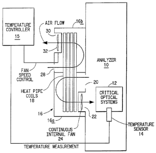
A preferred temperature control
strategy was devised to remove heat from the
analyzer and control the optical bench
temperature continuously at aim. A foil-type
RTD temperature detector is fastened to the
optical bench to serve as a measurement
input device for a PID control strategy, which
is truly aim-seeking. The control strategy
employs a heat pipe technology to remove
heat from the analyzer enclosure. A heat
pipe utilizes a fluid (such as an alcohol) to
remove heat by evaporation of the fluid at
an internal air circulation heat exchanger
and then recondensing the fluid at an
external air circulation heat exchanger. The
PID temperature controller achieves the
desired temperature setpoint by manipulation
of heat exchanger fan speeds. The heat
removal rate can be very precisely
controlled. In practice, both heat exchanger
fans could be controlled together, however,
to achieve optimal internal temperature
uniformity, the internal heat exchanger fan is
maintained at full speed and just the
external fan is controlled to adjust heat removal
rate. Optical bench temperature control is
maintained to plus or minus 0.1 degree C
vs. a typical temperature control band of
plus or minus 2 degrees C.
Le procédé préféré de régulation de température de la présente invention a été conçu pour éliminer la chaleur de l'analyseur et réguler à un niveau nominal continu la température d'un banc optique. Un détecteur de température à résistance du type "à feuille" est fixé sur le banc optique où il fait office d'organe de saisie de la mesure pour un procédé de régulation par action PID, approchant le nominal vrai. Le procédé de régulation met en oeuvre une technique de tube à chaleur pour éliminer la chaleur de l'enceinte d'analyseur. Ce tube à chaleur utilise un fluide (tel qu'un alcool) pour éliminer la chaleur par évaporation du fluide dans un échangeur de chaleur à circulation interne d'air. Le régulateur de température par action PID permet d'atteindre le point de consigne de température souhaitée en intervenant sur les vitesses des ventilateurs d'échangeurs de chaleur. Le taux d'élimination de la chaleur peut ainsi être très exactement régulé. Dans la pratique, il serait possible de commander ensemble les deux ventilateurs d'échangeurs de chaleur. Toutefois, pour une uniformité optimale de la température interne, le ventilateur de l'échangeur de chaleur interne est maintenu à plein régime, alors que le ventilateur de l'échangeur de chaleur externe est seul soumis à la régulation produisant le taux exact d'élimination de la chaleur. Grâce à ce procédé, il est possible de réguler la température du banc optique avec une marge de plus ou moins 0,1 DEG C, alors que cette marge était de plus ou moins 2 DEG C avec les procédés traditionnels de régulation de température.
Note: Claims are shown in the official language in which they were submitted.
Note: Descriptions are shown in the official language in which they were submitted.
For a clearer understanding of the status of the application/patent presented on this page, the site Disclaimer , as well as the definitions for Patent , Administrative Status , Maintenance Fee and Payment History should be consulted.
| Title | Date |
|---|---|
| Forecasted Issue Date | 2006-02-28 |
| (86) PCT Filing Date | 1995-07-21 |
| (87) PCT Publication Date | 1996-02-22 |
| (85) National Entry | 1997-02-04 |
| Examination Requested | 2002-04-24 |
| (45) Issued | 2006-02-28 |
| Deemed Expired | 2010-07-21 |
There is no abandonment history.
Note: Records showing the ownership history in alphabetical order.
| Current Owners on Record |
|---|
| E. I. DU PONT DE NEMOURS AND COMPANY |
| Past Owners on Record |
|---|
| MOESSNER, RICHARD CROSBY |

