Note: Descriptions are shown in the official language in which they were submitted.
CA 02196800 2004-11-04
1
VANE TYPE ORIENTER
Field of Invention
The present invention relates to an orienter, more particularly, the present
invention relates to a combination disks conveying type orienter.
Background of the Invention
Different types of disk type orienters have been used.
One such device is shown in U.S. patent 3,115,431 issued December 24, 1963, to
Stokes et al. This device includes the plurality of intermeshed rotating disks
mounted on
10 a plurality of substantially parallel side-by-side shafts positioned in a
plane. The disks on
the shafts are uniformly positioned intermediate disks on their adjacent
shafts. In the
arrangement described, the disks on adjacent shafts turn in the same
direction, except for
the last disks in the sequence which turn in the opposite direction. This type
of
arrangement (hereinbelow referred to as the Stokes arrangement) has been found
satisfactory particularly for use with long strands.
Another similar device is shown in the Burkner U.S. patent 4,666,029 issued
May
19, 1987 but wherein the disks on adjacent shafts are arranged in pairs in
side by side
relationship with the disks forming one of the pairs defining one side of an
orienting
2 0 passage and the disks forming the next axially space pair defining the
other side of the
passage. This arrangement (hereinafter referred to as Burkner's arrangement)
is also
satisfactory but the Stokes' arrangement is less complicated and appears to be
about as
effective in aligning the strands as the Burkner arrangement.
2 5 U.S. patents 4,380,285 issued April 19, 1983 to Burkner and 4,623,058
issued in
November 18, 1986 to Bossier each shows a combination of disks mounted on
spaced
parallel shafts and positioned above and intermediate stationary substantially
vertical
guide walls forming opposite walls of orienting passages through which the
strands fall
and are oriented. This type of orienter also has not been found to be
particularly
3 0 satisfactory for producing an end product with the required orientation
and strength.
219680
2
Canadian patent 920,529 issued February 6, 1973 to Turner et al. shows yet
another form of orienter wherein partition walls are designed to move to
prevent
plugging.
U.S. patent 3,807,931 issued April 30, 1974 to Wood et al. describes another
form
of orienter which uses a number of vertically stacked decks each formed by
stationary
vertical fms each provided with a vibrating cap that improve movement of the
wood
particle there between. Each deck has a number of fms that is a multiple of
the number of
fins in the deck immediately above it so that the fins on the upper deck
directly overlie
corresponding fins on the lower deck and the flow of strands is divided by the
upper deck
and the divisions so formed further subdivide by the next lower deck. In this
device, the
spacing between the fins on the top deck is about half the average length the
strands that
are to be oriented and the spacing between the upper and lower deck is defined
as the
distance greater than the average length of the strands. The orienting system
of this patent
clearly would not be effective for long wafers nor would it function well for
conventional
length (3 to 4 inch) strands.
U.S. patent 4,494,919 issued January 22, 1985 to Knudson et al. describes
another
form of apparatus for orienting strands particularly suited to orienting and
distributing of
long strands.
It is also known to use pre-orienters as described in Crittenden's et al. U.S.
patent,
2 0 5,325,954, wherein two orienting decks are stacked one on top of the other
with the axial
spacing between the disks on the uppermost deck, significantly wider spaced
than the
disks on deck therebetween.
In a concurrently filed co-pending application by Barnes titled Short Strand
Orienter, the concept of specific axial spacing or passage walls to size
(width) and
2 5 position the passages in one deck relative to those in the deck
immediately thereabove is
described and it is shown that significantly improved results are obtained
with an
arrangement wherein the passages through an upper deck are bisected into two
passages
by the next lower deck.
The vertical spacing between the bottom of the orienter and the top of the mat
or
3 0 lay-up being formed is very important i.e. the distance the strand are
free to fall
unrestrained laterally between the level where they are constrained by the
walls of the
CA 02196800 2004-11-04
3
orienting passages in the lowest deck of a mufti-deck orienting system has
also been
found to be important for retaining the orientation applied to the strands in
the orienter.
When disks are used, the gaps between the lower peripheries of adjacent disks
forming
the same wall of one of the orienting passages, further contributes to the
vertical spacing
and loss of orientation since it raises the bottom edge of the passage
significantly above
the bottom edge of the lowermost point on the peripheries of the disks. This
is a problem
when vanes are used as the walls of the orienting passages.
Disks were initially used in orienters to reduce plugging and to separate
strands
of different length so that the resultant consolidated composite product had
different
strength characteristics due to the positioning of the strands of different
length through
the thickness of the product. Positioning the longer wafers near the surface
improves the
bending strength of a panel product. Positioning the longer wafers near the
surface
improves the bending strength of a panel product.
The use of vanes significantly reduces throughput compared with the use of
rotating disks as the walls of the orienting passages. Similarly, the
throughput using a
single orienting deck with a narrow gap to get good orientation even when
rotating disks
are used as the walls of the orienting passages, has been found to be
relatively low and it
is necessary to make the orienter longer and to open up the gap between the
rotating
disks to increase throughput.
Brief Description of the Present Invention
The present invention provides an orienter capable or orienting wood strands
or
the like to improve their orientation relative to that obtainable using a
conventional disk
type orienter.
CA 02196800 2004-11-04
4
Broadly, the present invention relates to an orienter comprising a plurality
of
spaced parallel shafts, a plurality of axially spaced radial extending disks
mounted on
each of said shafts, said disks defining side walls of substantially
vertically extending
orienting passages, a group of said disks, each on different ones of said
shafts defining a
side wall of one of said substantially vertically extending orienting
passages, vane
members extending between a pair of adjacent said disks forming the same said
side wall
of said passage and closing a gap formed between lower adjacent peripheries of
said
adjacent disks.
Preferably, each said vane will be in substantially the same vertical plane as
its
respective adjacent of said disks whose gap therebetween said vane is closing.
Preferably, each of said disks will be provided with a circumferential groove
extending around its periphery and said vane members will be received within
said
groove to maintain said vane members in alignment with said adjacent disks.
Preferably a bottom will be formed to said groove by an annular insert
positioned
between said disk element of each one of said disks.
Preferably, each of said disks will be provided with notches circumferentially
spaced around its periphery and extending radially inward by a selected
distance and
wherein a lower edge of said vane members will extend slightly below a plane
containing said parallel shafts a distance less than the radius of said disks.
Preferably, all said disks will have essentially the same radius.
Preferably, said group of disks forming said one side wall of each passage
will be
mounted on alternate shafts of said plurality of shafts and wherein disks on
alternate
shafts are mounted axially spaced midway between the disks on the shafts
between said
alternate shafts.
CA 02196800 2004-11-04
4a
Preferably, wiper means will be provided on each said shaft in the position to
project above an upper edge of its adjacent said vane to clear strands
therefrom.
Brief Description of the Drawings
Further features, objects and advantages will be evident from the following
detailed description of the preferred embodiments of the present invention
taken in
conjunction with the accompanying drawings in which;
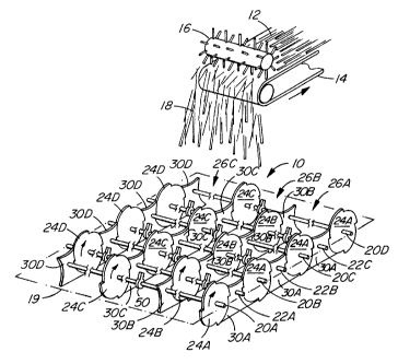
Figure 1 is a schematic isometric exploded view illustrating a portion of an
orienter constructed to incorporate vanes in accordance with the present
invention but
showing the disks more widely spaced so the concept will be more evident.
Figure 2 is a side view of a small portion of the orienter showing the vanes
in
position and with a portion of one of the disks broken away.
Figure 3 is a section along the line 3-3 of Figure 2.
Figure 4 is a schematic illustration of a multi-level orienter constructed
incorporating the present invention.
2196800
Figure 5 is a graph of mean angular deviation versus height above the mat of
the
lower most part of the disks or vanes.
Description of the Preferred Embodiments
As shown in Figure 1, the orienter 10 is provided with strands or the like 12
from
5 an infeed conveyor 14 and a distributor roll 16 (preferably spiked) which
distributes a
stream 18 of wood strands over the upper end of the orienter 10.
The wood strands normally used with the orienter system of the present
invention
may have any reasonable length - generally, less than about 12 inches, a
thickness less
than about 0.25 inches, normally less than about 0.05 inches, a width
generally about '/2
inch and up to about 3 inches with a length to width aspect ratio of at least
2.
The orienter 10 in the illustrated arrangement formed by a plurality of
alternate
shafts and a plurality of intermediate shafts all arranged in a substantially
the same plane
and all extending substantially parallel to each other. Shafts have been
numbered 20A,
20B, 20C and 20D commending the left side of the drawing and the shaft by the
reference
numerals 22A, 22B, 22C commencing with 22A adjacent to the left side of the
drawing
so that the intermediate shaft 22A is between the alternate shafts 20A and
20B, 22B
between the shafts 20B and 20C and the shaft 22C between the shafts 20C and
20D. In
Figure 1, the axial spacing of the disks has been exaggerated to more clearly
illustrate the
invention.
2 0 The plane in which the shafts are retained is schematically indicated by
the dash
dot line 19.
The disks 24A on the alternate shafts 20A, 20B, 20C and 20D combine to form
one wall of a vertical passage 26A. The letter A is used to designate those
disks that
rotate in a single plane substantially perpendicular to the plane 19 and
define at major
2 5 portion of one wall of the first (front in the drawing) vertical passage
or orienting passage
26A.
In the illustrated arrangement, a second set of disks 24B are mounted on the
intermediate shafts 22A, 22B and 22C. These disks 24B define a second wall of
the
passage 26A substantially parallel to the wall formed by the disks 24A and
also form a
3 0 wall of the next passage 26B, i.e. the second passage from the front of
the drawing, the
opposite side of which is defined by the disks 24C on the alternate shafts
20A, 20B, 20C
2196800
6
and 20D and as described, these disks 24C combine to form a wall of the next
vertical
orienting passage 26C, the opposite side of which is defined by the disks 24D
and so on
across the width of the orienter 10.
It will be apparent that the walls on the opposite sides of the passages 26A,
26B
and 26C are defined primarily by disks on adjacent shafts.
The disks on the intermediate shafts are axially spaced substantially midway
between the disks on alternate shafts, i.e. the disks 24B are spaced midway
between the
disks 24A and 24C and the disks 24C are spaced midway between the disks 24B
and
24D, etc.
The arrangement described is what has been defined above as the Stokes
arrangement i.e. uses the disk arrangement disclosed in the Stokes et al
patent referred to
above. It will be apparent that if a Burkner type arrangement is used, a
similar structure
could be formed.
It will be apparent that there is a gap G between the disk 24A on the various
shafts
20A, 20B, 20C and 20D and between the disks 24C on the same shaft as well as
between
the disks 24B on the shafts 22A, 22B and 22C and the disks 24D on these same
shafts, i.e.
there is gap formed between adjacent disks defining a wall of the vertical
orienting
passages 26A, 26B, 26C, etc.
The gap G is filled by a vane or vane member 30 which completely closes off
the
2 0 gap G. In the illustrated arrangement, the vane member 30 positioned
between adjacent
disks such as the disks 24A on shafts 20A and 20B is mounted on a suitable
bearing not
shown on the shaft 22A and mates with the adjacent disk 24A as will be
described below
to substantially completely fill the gap G and extend for a distance above the
shaft 22A on
which it is supported.
2 5 Each of the vane members 30 has an upper surface or edge 32 that is
preferably
substantially concave and a substantially straight line bottom surface or edge
34 that is
preferably substantially parallel to the plane 19 containing the axes of the
shafts. If
plugging tends to occur at the top of the vanes the concave surface may be
replaced with a
sloped surface sloping down in the direction of strand movement by the disks,
however
3 0 regardless of the shape of the upper edge 32 the edge must be positioned
well below the
upper periphery of the adjacent axially spaced disks.
2a96~00
In the arrangement illustrated in Figure 2, the solid line arrangement
utilizes
discreet elements 30 positioned between each of the disks 24A and the bottom
edge of the
elements 30 project down to the position slightly higher than the lower most
radial
position of the disks 24A, i.e. the height H is preferably slightly less than
(in the order of
1/4 inch) the radius R of the disks 24A.
If desired, the vane 30 may extend well below the radius R as indicated by the
dash lines 36. In the illustrated arrangement, the dash lines 38 indicate that
each of the
elements 30 are discreet elements joined together at the line 38. However,
they may be
made as a continuous element extending substantially the length of the
orienter 10.
On the subject of mounting, it is preferred to divide the vane into an upper
section
40 separate from a lower section 42 as indicated by the split line which
intersects the shaft
on which the vane 30 is mounted to facilitate removal or application of the
vanes 30 by
separation into the two parts..
The upper edge 32 of the vane is made substantially concave in the
illustration but
may be modified to reduce the possibility of lodging. In each of the disks 24
is provided
with grooves or notches 46 to help to clear any strands that may be supported
on the
upper edges 32. Also, a wiper 48 is mounted on each of the shafts in a
position adjacent
to the vane 30 and is provided with a spike or the like 50 that also tends to
clear the upper
surface 32 and to ensure strands do not lodge in the passages over the shafts.
2 0 In the illustrations of Figures 1 and 2, the vanes 30 have been further
identified by
the reference letter A, B, C or D depending on which of the disks 24A, B, C or
D it
cooperates with to form a wall of a passage.
As can be seen in Figure 3, in the preferred construction each of the disks 24
is
formed by a pair of relatively thin outer disks 52 and 54 and an inner disk or
spacer 56
2 5 which spaces the outer disks 54 and defines the bottom of the
circumferential groove 58
in each of the disks 24. The spacing between the adjacent faces of the disks
52 and 54
define the width of the circumferential groove 58 which is slightly wider than
the
thickness of the vanes 30 to accommodate the vanes therein. The depth of the
grooves 58
will normally be in the order of about at least %2 inch and not exceed about 1
%2 inches, i.e.
3 0 the radius R is 3/4 to 1 %i inches less than the radius r (see Figure 2).
The depth of the
2196800
8
groove 58 is set so that it retains the vane 30 in position but is not so deep
as to provide a
significant problem of strands penetrating the groove and becoming lodged
therein.
The depth of the notches 46 distance between the outer periphery of the disks)
20
or 22 and the bottom of the notches 46 will generally be no greater than the
difference
between R-r.
In operation, it will be apparent that all of the disks or shafts are driven
preferably
in the same direction as indicated by the arrow in Figure 2 and the wipers 48
are
connected to the respective shafts 20 and 22 to rotate there with. The height
of the edge
34 permits the formation of a relatively uniform distance between the bottom
of the
orienter and the top 80 of the mat 82 being formed (see Figure 4) which
improves
significantly, the resulting orientation of the strands passing there through
i.e the added
height of the gap G is essentially eliminated.
Figure 4 shows a modification of the present invention wherein an orienter
similar
to the orienter described in Applicant's co-pending application, Short Strand
Orienter
wherein a plurality of decks are provided one above the other. In this
arrangement, the
bottom shafts are indicated at 60A and form in effect a bottom deck, the
intermediate
shafts at 60B which form an intermediate deck and the upper shafts at 60C
which form
the top deck. Each of these shafts 60A, B and C represent a plurality of
shafts 20A, 20B,
20C, 20D, 22A, 22B, 22C, etc. defining an orienter at each level. The disks
62A and the
2 0 shafts 60A are set relatively close together and define the width of the
bottom orienting
passages indicated at 64A, B, C and D which define the passages of width
sufficient to
obtain the required degree of orientation of the strands. The passages 64A, B
in effect
bisect the passages formed between the disks 62B on the shaft 60B i.e. passage
70A or
70B and which in turn bisect the passages) 68 formed between the disks 62C on
the
2 5 shafts 60C.
Suspended below each of the disks 62C is a relatively long vane 66 (designated
as
66A and 66B) in Figure 4 which define a relatively wide passage 68. This wide
passage
is as above described divided into a pair of preferably equal width passages
70A and 70B
by the disk 62B and its vane 74 extending therebelow.
3 0 As above indicated, the passages 70A are bisected by the disks 62A into
the
passages 64A, 64B, 64C and 64D. The vanes 76A and B extend downwardly from the
2196800
9
disks 62A with the bottom edges of all of the vanes 66A, 66B, 74, 76A and 76B,
all being
positioned in substantially the same plane 78 which is substantially parallel
to the top 80
of the mat 82 being formed on the belt or the like collective means 84 ie the
distance
between the top of the conveyor 84 and the edges or plane 78 is substantially
uniform .
The above described embodiments shown in Figure 4 permits the formation of an
orienter wherein throughput is improved as described in the said application.
In the embodiment shown in Figure 4, the wipers 48 with spikes 50 have not
been
shown but they will be provided as required to ensure that the upper edges of
the various
vanes and of the shafts are kept clear and plugging is substantially avoided.
Example
Using a single deck or plurality of decks positioned one above the other and
wherein each deck was made as in Stokes arrangement using 16 inch diameter
disks on 2
inch diameter shafts. The disk spacing through the bottom disk in all cases
was 1 %2 inch
(passage width). A 6 inch strand mixture was fed to the orienter and the
orientation
measured when operating using different numbers of decks.
As shown in Figure 5 with only one disk (bottom deck) the orientation attained
was poorest and that with two decks wherein the bottom disk had vanes as
defined herein
the orientation was significantly better than with any number of decks were
used.
It will be apparent that in all of the embodiments, the vanes are relatively
thin, flat
2 0 elements, i.e. planer elements and preferably are contained within the
plane of the disks
with which they cooperate.
In some cases, adhesive application to the strands may tend to accumulate and
some means for removing this adhesive from the peripheral grooves in which the
vanes
are received may be added, e.g. scrapers, nonstick coatings, etc.
2 5 Having described the invention, modifications will be evident to those
skilled in
the art without departing from the scope of the invention as defined in the
appended
claims.