Note: Descriptions are shown in the official language in which they were submitted.
21g6828
._ 1
UNDERWATER CABLE BURIAL MACHINE USING
A SlNGLE CABLE FOR TOWING AND LIFTING
Bark~round of the Invention
The present invention relates to underwater cable burial machines. In
particular, the invention relates to an underwater cable burial m~hine which uses
a single cable for both towing and lifting.
Undelwater burial machines are used to bury communications cables in the
10 sea bottom in an effort to protect the cables from damage. These m~chines plow a
groove in the seabed beneath a body of water, and they sim~llt~neously lay a cable
into the groove wich they have plowed. Burial m~chines use at least one plow
blade to cut a groove into the seabed imme~ tely in front of a cable laying
mech~ni~m The cable is then placed into the groove thus formed in order that it
5 will be somewhat beneath the surface ofthe seabed. After the cable has been laid
into the groove, water pressure and undel~aler cwlenl~ eventually cause the
vertical walls of the groove to collapse and move sand and soil into the groove,
thereby covering the cable and ~ssi~tin~ in the overall burial operation.
Periodically ~e blllial m~chines must be returned to ~e s~ ce for
20 ~--A;-~IP~ ce or for transpol~lion from a site. While it is preferable to be able to
minimi7~ the number of cables in the water, in order to avoid ~l~ma~e to the
co.~....l..~ications cable which is being laid, and to avoid cables l)eco~ g
çnt~n~led, in order to raise the m~hines of the prior art to the surface, more than
2196828
one cable has been needed. Alternatively, the machines used complicated schemes
by which they could be towed by a combination towing/umbilical cable, and then
lifted by that cable when a relatively large yoke was pivoted from the front of the
m~chine (towing position) to the a point above the machine (lifting position).
5 Such arrangements were unwieldy, and they increased the likelihood of damage to
or ent; n~lement of the cables or damage to the m, chine.
In view of the foregoing problems which were not solved by the cable
burial machines of the prior art, an improved cable burial mAchine which uses
single cable for both li~ng and towing, but which avoided the problems of the
10 prior art would be desirable.
Summar~,r of the Invention
In accordance with the present invention, a new design approach has been
disclosed which solves the problem of being able to both tow and lift a cable burial
15 mAc.hine using a single cable. The new design uses a relatively short, strong steel
retractable cable which is attached to a re'¢action mech~ni~m on the cable burial
m~chine. The retractable cable passes through a cable guide which is mounted on
the top of the cable burial -Ahine over the cable burial mA-hine's center of
gravity. The other end of the retractable cable is attached to the towing/umbilical
20 cable at a point which is at least as far away from the towing point on the m;lc11ine
2196828
as the cable guide is from the towing point. The connection point distance from
the towing point is important, in that it will be necessaIy to retract the connection
point to the cable guide, so if the retractable cable is attached any to the
towing/umbilical cable, any closer than the towing/umbilical cable is connected to
5 the towing point than it will not be possible to bring the connection point back to
the cable guide.
When lifting of the cable burial machine is desired, the retractable cable is
pulled back through the cable guide by the retraction mech~ni~m pulling the
towing/umbilical cable with it. When both cables have been withdrawn to ~e
0 cable guide, the towing/umbilical cable will be over the center of gravity of the
cable burial m~rhine, so it can be used to lift the cable burial mac_ine to the
surface.
Brief De~cription of the Drawin-J
In the Drawing:
FIG. 1 is a side view illu~llaling the improved cable laying mech~ni~m of
the present invention on a cable burial m~hine being towed by a surface vessel in
a cable laying operation;
FIG. 2 is a side view illu~llal~ the improved caUe laying meçh~ni.~m of
20 the present invention illustra~ng the m~nner in which the towing cable is able to
2196828
lift the cable burial machine from a point above the center of gravity of the towing
machine;
FIG. 3 top view of the retraction mech~ni.cm and the cable guide of the
present invention; and
FIG. 4 is a side view of the retraction mech~nism and the cable guide of the
present invention.
Detailed Des~ ,tion of the E'~ ~f~ d Embodiment of the Invention
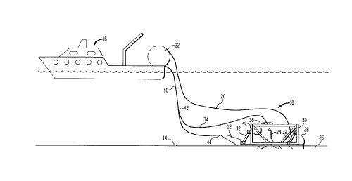
Referring to FIG. 1, a simplified side view of a cable laying m~hine 10
employing the single cable lifting and towing system of the present invention is
shown. The cable laying machine 10 is mounted on a sea sled 12 which is being
towed along the seabed 14 by a surface vessel 16. The towing is accomplished by
means of a combination towing/umbilical cable 18.
During the towing operation, a co~ ications cable 20 is unspooled from
a spool 22 on the vessel 16. As the sled 12 is pulled forward, a plow 24 cuts a
groove 26 in the seabed 14, and the co...~ ications cable 20 is laid into the
groove 26 by cable laying a~p~alus 28 which is located on the rear of a carriage
30 which is fixed to the sled 14 using a four bar linkage 32. As will be understood
by those sl~lled in the art, the four bar link~e 32 allows the c~ ge 30 to be
moved up and down relative to the sled 12. This p~.. ~ the plow 24 and cable
2196828
~ laying apparatus 28, both of which are attached to the carriage 30, and bo~ of
which are shown to extend through the flat bottom of the sled 12, to be moved up
and down relative to the bottom of the sled 12. The four bar linkage 32 allows the
plow 24 and the cable laying appalalus 28 to be moved up above the bottom of the
5 sled 12 when the sled 12 is recovered onto the deck of the vessel 16 for
transportation or m~int~n~nce. In addition, the four bar linkage 32 can be used to
adjust the depth of the groove 26 in the event that that becomes necessary due to
the m~kellp of the seabed 14, i.e., if a rock layer is encountered below the surface
of the seabed 14 at a depth which is less than the normal cable laying depth. By
10 way of example, if the normal cable laying depth was twelve inches, and a rock
layer was encoul~leled ten inches below the surface of the seabed 14, then the four
bar link~e 32 could be adjusted using hydraulic cylinders (not shown) so that the
plow teeth only ext~n~le~l somewhat less than ten inches below the seabed 14,
thereby preventing ~l~m~ee to the teeth while allowing the burial operation to
1 5 cnntimle
As will be understood by those skilled in the art, the combination
towing/umbilical cable 18 is used to both tow the sled 12, and to car~y hydraulic
fluid and electrical signals between the vessel 16 and the sled 12.
With co~ e~l reference to FIG. 1, the present invention makes use of a
20 re~actable cable 34, a cable guide 36 mounted on top of the carriage 30 at the
~ 2196828
center of gravity of the burial m~~hine 10, and a retraction mech,lni~m 38 (See
FIGS.3 and 4), which is illustrated by the drum 40, to which one end of the
retractable cable 34 is attached.
The other end of retractable cable 34 is attached to the towing/umbilical
5 cable 18 at a point 42 which is at least as far from the towing point 44 on the sled
12 as the towing point 44 is from the cable guide 36.
Referring to FIG. 2, when recoveIy of the sled 10 onto the surface vessel 16
is desired, the retraction mech, ni~m 38 is operated to pull the retractable cable 34,
and the ~ çhm~nt point 42 (i.e., where the retractable cable 34 connects to the
10 towing/umbilical cable 18) back to the cable guide 36. When the cables 34, 18
have been pulled back to the cable guide 36, so that the attachment point 42 is at
the cable guide 36, the retractable cable 34 will be wound unto the drum 40 (See
FIGS.3 and 4), so it is not visible in FIG. 2. In ~is position, the towing/umbilical
cable 18 can be used to raise the burial m~~.hine 10 from above its center of
15 gravity, up to the sll~ce vessel 16. As the lifting of the burial m~hine 10 will be
from above the center of gravity ofthe burial m~c~ine 10, the burial machine 10
will remain horizontal as it is lifted without any need for any type of complicated
towing hardware, or without the need for multiple cables extending up to the
surface vessel 16. By way of ~ .lG, for a sled 10 which is on the order of
~196828
~ twenty feet long, the retractable cable could be well under one hundred feet long,
no matter how deep the cable burying operation is being conducted.
Referring now to FIGS. 3 and 4, the cable guide 36 is shown to be a
toroidal structure. While other shapes may be used, it is important that a shape be
5 selected which does not cause chafmg to the retractable cable 34, or to the
towing/umbilical cable 18.
The cable guide 36 is preferably mounted on a plate 46 which includes
means for adjusting its location relative to the carriage 30 (See FIGS. 1 and 2), in
order to insure that the cable guide 36 is over the center of gravity of the cable
10 burial m~r~ine 10. In the l,lefelled embodiment of the invention, the plate 46 is
bolted to arms 48, 50 which are attached to the carriage 30. Accordingly, by
ch~nging the loca~on of the bolts (not shown) in the elongated holes 52, the cable
guide 36 may be selectively moved over the center of gravity of the cable burial
m~c.hine 10.
The cable drum 40 which receives and dispenses the retractable cable 36 is
also shown in FIGS. 3 and 4, and a motor 56 which is ~r~fe.ably driven by
hydraulic means (not shown) is connected to the cable drum 40 by means of an
ro~,liate, reversible drive me~nism 58, which may be a worm gear, a chain
drive, or a similar means for l~ g power from thé motor 56 to the drum 54.
2196828
~_ 8
The combination of the drum 54, dle motor 56, and the drive mech~nism 58, make
up the cable retraction mech~ni~m 38, shown in FIGS. 1 and 2.
As will be obvious to those skilled in the art, numerous changes can be
made to the preferred embodiment of the invention without departing from the
5 spirit or scope of the invention described herein.