Note: Descriptions are shown in the official language in which they were submitted.
-
21968~8
F~YTRT~ BULK CONT~TN~P WITH ~U~.~.lN~ SIDE BEAMS
FIELD OF THE INVENTION
The present invention relates to bulk containers and
in particular, flexible bulk containers having supporting
vertical side beams which prevent bulging of the container
when loaded with flowable materials.
BACKGROUND OF THE INVENTION
To store and transport flowable materials such as
grain, chemicals, fertilizers and minerals, intermediate or
semi bulk shipping containers have been developed. These
containers are often cylindrical in design and are formed
from a flexible woven material. Approximately 1,000 to
3,000 lbs. or more of bulk material may be loaded within
the containers which customarily have top loading and
bottom discharge features. Flexible intermediate bulk
containers are easily transported and stored in an exposed
condition and can be readily stacked for high density
storage or transportation.
U.S. Letters Patent No. 4,194,652 describes a flexible
intermediate bulk shipping container. A woven container is
provided which includes a bottom portion and an upstanding
side portion. The side portion is formed from one or more
panels sewn together at the vertical edges. The lower edge
of the cylindrical side portion is sewn to the periphery of
the bottom portion, which includes a discharge spout. A
similar spout is situated at the top of the container to
facilitate in the loading thereof.
As a result of the inherent properties of flowable or
bulk material, a lateral force generated by the bulk
2196848
material is exerted upon the side wall panels of flexible
bulk containers. Flexible circular side walls tend to
uniformly distribute the lateral force caused by the bulk
material about the containers. However, the lateral force
tends to cause a bulging of the container. Bulging is an
undesired effect as it distorts the containers causing a
loss of storage space when the containers' are stacked
together. In the extreme, bulging can cause of rupture of
the containers and a spilling of the containers' contents.
This is especially undesired when the contents are chemical
in composition.
Transportation, be it by truck, train or ship,
subjects flexible containers to forces of momentum.
Hence, acceleration or deceleration of the transporting
vehicle may cause a shifting of the contents of the
containers and of the container themselves. To ease some
of the problems associated with transportation, flexible
intermediate bulk containers have been developed with rigid
supporting members.
U.S. Letters Patent No. 5,025,925 describes a flexible
intermediate bulk container flexible container having
support pillars associated therewith. The outer surface of
the container has vertically placed channels which receive
the support pillars. The bottom ends of the support
pillars are connected to a wooden pallet. The patent
describes that the pillars are useful in reducing strain
placed upon the upper end of the forward support pillars
and the lower end of the backward support pillars when
transport velocity is reduced.
U.S. Letters Patent No. 4,019,635 describes a tubular
cardboard or corrugated board bulk intermediate container
which rests within a sleeve that is secured to a bottom
-
2196848
--3--
pallet. The patent further describes that the relative
movement of the container within the sleeve provides for
the absorption of a large proportion of the impact energy
resulting from transportation of the container.
Because flexible intermediate bulk containers are
collapsible, attempts have been undertaken to create self
standing side walls to ease in the filling of the
container.
U.S. Letters Patent No. 4,903,859 describes a flexible
intermediate bulk container which incorporates rigid panels
into the side walls of the container. The patent describes
that the rigid panels permit the container to stand alone
when filled.
While employing some form of supporting structure, the
aforementioned patents do not address or attempt to
alleviate the problem of container bulging.
One attempt to overcome the problems associated with
bulging involves the placement of flexible containers
within a rigid outer cubical frame work structure.
Examples of such applications are found in the following
patents: U.S. Letters Patent Nos. 5,437,384; 4,834,255;
4,901,885; 4,927,037; 5,052,579; 5,071,025; 5,282,544;
5,289,937; and 5,407,090. However, this approach is
burdensome, expensive and complicated as it requires the
construction of an external supporting structure.
It is therefore an object of the present invention to
overcome the draw backs associated with bulging of flexible
bulk containers under load. This object is achieved
through the use of vertical side beams positioned about the
21968~8
side wall panel of the flexible bulk container.
SUMMARY OF THE INVENTION
The object of the present invention is achieved by
providing a flexible bulk container having vertically
placed rigid side beams positioned about the side wall
panel of the container. The side beams are connected at
the top and at the bottom of the container in such a manner
that the side beams bear the lateral forces of the flowable
materials being contained and transfer those forces
vertically to the top and bottom of the container as well
as horizontally to the side wall panel.
The rigid side beams may be formed in a variety of
shapes and may be composed of numerous materials. However,
the shape and composition of the rigid side beams should
function to transfer force longitudinally with relatively
little deflection. A preferred shape for the rigid side
beams is a triangular or V shaped profile as the material
to strength ratio makes this shape economically feasible.
A 45 degree angle at the apex is preferred, with the apex
preferably pointing towards the center of the container.
A commercially available product known as ~angle board' or
Uedge board~ would be suitable for constructing the side
beams. It has a V shaped profile and is made of paper
fiber or plastic.
The side beams may be held in place by a variety of
fastening me~hAn;cms. The use of an adhesive to affix the
side beams to the side wall panel of the container may be
employed. Additionally, the side wall panel may contain
sleeves or pockets which receive the side beams and hold
them in position about the side wall panel. Laminating the
side beams to the side wall panel is also possible. In an
-
21968~8
alternative embodiment of the invention in which the
container has a rigid top and bottom panel, molded
receptacles in the top and bottom panels may be provided to
secure the ends of the side beams and position them
vertically about the side wall panel.
The spacing and number of side beams is dependent on
the characteristics of the flowable material that is to be
contained. Ideally, the spacing and number of side beams
should result in the container being relatively cubical in
appearance with bends in the side wall panel occurring
between side beams and at the corners of the container.
This is often accomplished by using eight side beams paired
into sets of two which are spaced equidistant from the
other sets about the side wall panel. The side beams act
to transfer the lateral bulge force to the areas in the
side wall panel where the bends occur. More importantly,
the side beams transfer the lateral bulge force away from
the side wall panel to the top of the container. This is
accomplished by connecting the top ends of the side beams
at or near the top panel of the container.
The flexible bulk container of the present invention
can be made inexpensively from standard bulk packaging
material. When the container is empty, it is fully
collapsible and therefore economical to ship. When the
container is filled with flowable materials, it conforms to
a relatively cubical shape essentially eliminating the
problems associated with a ~bulged" container and provides
a more efficient bulk shipping and storage container.
Additionally, the flexible bulk container of the present
invention has improved stacking capabilities when loaded as
a result of more evenly distributed forces and the added
strength of the side beams.
2lg68~8
BRIEF DESCRIPTION OF THE DRAWINGS
FIG. 1 is an isometric, cut away view of a first
embodiment of the flexible bulk container showing side
beams positioned with top and bottom sleeves.
FIG. 2 is an isometric top view of a second embodiment
of the flexible bulk container showing a rigid top and
bottom panel.
FIG. 3 is an isometric top view of a third embodiment
of the flexible bulk container showing an interconnection
between sets of side beams.
FIG. 4 is an isometric top view of a third embodiment
of the flexible bulk container showing the side beams as
plates.
FIG. 5 is an isometric top view of a fourth
embodiment of the flexible bulk container showing side
beams positioned with top and bottom pockets.
FIG. 6 is an isometric top view of a fifth embodiment
of the flexible bulk container showing the side beams
positioned with a laminated sheet.
FIG. 7 is a partial cross sectional schematic view of
the first embodiment of the flexible bulk container showing
side beams positioned on the outer side wall surface of the
container.
FIG. 8 is a partial cross sectional schematic view of
a sixth embodiment of the flexible bulk container showing
side beams positioned on the inner side wall surface of the
container.
2196848
FIG. 9 is an isometric top view of a seventh
embodiment of the flexible bulk container showing a top
fill opening, lifting loops and a pallet.
FIG. 10 is an isometric bottom view of the seventh
embodiment of the flexible bulk container showing a bottom
dispense opening.
FIG. 11 is an isometric top view of an eighth
embodiment of the flexible bulk container showing straps
connecting the top ends of the side beams.
FIG. 12 is a isometric bottom schematic view of the
eighth embodiment of the flexible bulk container showing
the positioning of straps connecting the bottom ends of the
side beams.
DETAILED DESCRIPTION OF PREFERRED EMBODIMENTS
With reference to the figures where like elements have
been given like numerical designation to facilitate an
understanding of the present invention, and particularly
with reference to the embodiment of the bulk container of
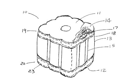
the present invention illustrated in FIG. 1, the bulk
container may be constructed of a substantially flexible
container 10 having a top panel 11 and a bottom panel 12
interconnected by an upst~n~;ng side wall panel 13 defining
a collapsible chamber 14 for flowable materials.
Preferably, four or more side beams 15 extend in a
substantially vertical direction about side wall panel 13
in spaced relation.
Flexible container 10 may be partially formed of a
flexible material. As an example, side wall panel 13 may
be formed of a flexible material and top panel 11 and/or
-
21968~
--8--
bottom panel 12 may be formed of a relatively rigid
material. Preferably, flexible container 10 is constructed
entirely of a flexible material.
The flexible material forming flexible container 10
may be a woven material, and in particular, a woven
polypropylene material or a woven polyethylene material.
However, it is to be understood that other flexible
materials may be utilized in constructing flexible
container 10. For example, flexible container 10 may be
formed of a paper material or a synthetic material.
Examples of synthetic materials may include plastics or
rubber.
Flexible container 10 may be formed of multiple
layers. For example, flexible container 10 may be composed
of a layer of relatively permeable woven material and a
layer of relatively impermeable material. The relatively
impermeable material may be an external or internal
coating. Preferably, the relatively permeable woven
material is a woven polypropylene material, and the
relatively impermeable material is a synthetic film
material. Examples of synthetic film material include
nylon, polyethylene, polypropylene, polyvinyl chloride and
polyesters.
As shown in FIG. 2, top panel 11 and/or bottom panel
12 may be constructed of a substantially rigid material.
While it is understood that various materials having
rigidity may be utilized to construct top panel 11 and/or
bottom panel 12, it is preferred if the rigid material is
corrugated paper, wood, plastic or metal.
With reference to FIG. 1, it can be seen that side
wall panel 13 may be a formed of a single panel joined
-
- 2i968~8
together at its ends. Alternatively, side wall panel 13
may be formed of separate side wall panels which are joined
together to form side wall panel 13. As an example, side
wall panel 13 may be constructed from four separate side
vall panels. The separate side wall panels are preferably
joined together at their respective ends to adjacent
separate side wall panels. It is to be understood that
side wall panel 13 may be joined by any fastening
procedure. The fastening procedure would depend upon a
variety of construction factors, as for example, the type
of material utilized to form side wall panel 13. However,
in an embodiment in which side wall panel 13 is made of a
woven material, it would be preferred if the fastening
procedure was accomplished through sewing or stitching.
Again with reference to FIG. 1, it is preferred if the
number of side beams 15 is between four and twelve. It is
even more preferred if the number of side beams 15 is
eight. Side beams 15 may also be in sets of two. When
configured in sets of two, it is preferred if the sets of
side beams 15 are positioned opposite each other about side
wall panel 13.
As illustrated in FIG. 3, side beams 15 forming the
sets of side beams 15 may be interconnected. The sets of
side beams 15 may be interconnected with any type of
connecting member 16. Connecting member 16 is preferably
made of the same material forming side beams 15
Connecting member 16 may be a rod, tube or similar designed
device, and its placement between side beams 15 forming the
set of side beams may be in any configuration or angle. In
a preferred embodiment, connecting member 16 is of a design
such that interconnected side beams 15 form a plate, as
shown in FIG. 4
- 2~968~8
--10--
FIG. 1 shows side beams 15 extending substantially
vertically about side wall panel 13. Preferably, side
beams 15 may be positioned at an angle in the range of lo
to 90 degrees in relation to bottom panel 12. More
preferably, side beams 15 may be positioned at an angle in
the range of 45 to 90 degrees in relation to bottom panel
12. And even more preferably, side beams 15 may be
positioned at an angle of about 90 degrees in relation to
bottom panel 12.
Again with further reference to FIG. 1, side beams 15
may extend substantially the entire height of said side
wall panel 13. To effect distribution of the lateral bulge
forces, it is preferable that side beams 15 be formed of a
substantially rigid material. The rigid material forming
side beams 15 may be any material having rigidity such that
the distribution of lateral bulge forces is accomplished.
Preferably, such rigid material is corrugated paper, wood,
plastic or metal. Side beams 15 may also be designed in a
variety of shapes. For example, side beams 15 may be
tubular. In addition, side beams 15 may be triangular
shaped or V shaped in cross section.
Bulge force is equal in all lateral directions.
Hence, without the use of side beams 15 to transfer the
bulge force, flexible container 10 would be circular or
round. To obtain the desired cubical shaped flexible
container 10 which is portrayed in the figures, side beams
15 should be positioned about side wall panel 13 in order
to effect an equal diversion of lateral bulge forces.
Determining the positioning of side beams 15 may involve
the following consideration.
Compute the circumference of a theoretical circle
-~ 2l96~ 48
--11--
using as a guide (1) the diameter of a loaded circular
flexible container without side beams(no restrictions
impending the lateral bulge force)and(2) including in the
computation the expected elasticity or elongation of the
material forming side walls panels of the container.
Divide the computed circumference by the number eight (two
side beams per side or eight segments which maximizes equal
distribution of bulge force). The resulting number is the
distance on the circumference of the flexible container lo
that side beams 15 should be positioned apart from each
other. However, due to considerations such as product
manufacturing tolerances and efficiencies, side beam 15
profiles, side wall panel 13 material selection, content
load requirements and others, the positioning of side beams
15 does not need to be located as precisely as described
above. In addition, it might be beneficial for reasons
other than design (e.g., stacking, handling considerations,
side beam construction) to use more than two side beams 15
per side. In this situation, side beams 15 may be
positioned symmetrically about side wall panel 13. If a
side beam 15 is positioned at the midpoint of a side of
side wall panel 13, the positioning of other side beams 15
may be done to balance out the residual bulge force or to
more efficiently handle stacking load.
In the embodiment wherein side wall panel 13 has four
distinct sides, as for example when formed of four separate
(but joined) side wall panels 13, one possible construction
of the present invention would be to position four side
beams 15 in the center of each separate side wall panel 13.
In a preferred embodiment, two side beams 15 are positioned
about each of the four side wall panels 13.
Side beams 15 may be positioned about side wall panel
13 in various ways.- Side beams 15 may be attached directly
2196~ i8
-12-
to side wall panel 13 or side beams 15 may be directly
attached to top panel 11 and bottom panel 12. The
attachment means may be dictated by the type of material
forming flexible container 10. In the embodiment of the
present invention in which side beams 15 are fixedly
attached to side wall panel 13, side beams 15 may be
attached by adhesive. In the embodiment of the present
invention in which side wall panel 13 is made of a flexible
metal, side beams 15 may be welded to side wall panel 13.
In the embodiment in which side wall panel 13 is made of
woven material or paper, a mechanical fastener may be
utilized to accomplish attachment. An example of a
m~c-h~n;cal fastener is a staple or stitch.
As illustrated in FIG. 1, side beams 15 may be
positioned about side wall panel 13 by retaining means 17
which receive and maintain side beams 15 in a substantially
vertical position in relation to bottom panel 12.
Preferably, retaining means 17 are configured as sleeves
18.
Again with reference to FIG. 1, sleeves 18 may be
secured to side wall panel 13. In one embodiment of the
present invention,-sleeves 18 are positioned at top end 19
of side wall panel 13 and bottom end 20 of side wall panel
13 whereby the ends of side beams 15 may be fixedly
attached to side wall panel 13. Sleeves 18 may extend
continuously around side wall panel 13 at top end 19 and
bottom end 20. However, sleeves 18 may also extend
noncontinuously around side wall panel 13 at top end 19 and
bottom end 20.
As seen in FIG. 5, sleeves 18 may preferably be in the
form of multiple pockets 21 whereby a set of two pockets,
' -
2l96~ll8
one positioned at bottom end 20 and one positioned at top
end 19, receive and maintain individual side beams 15 in a
substantially vertical position about side wall panel 13.
Instead of a set of two pockets, pockets 21 may be a single
pocket extending the height of side wall panel 13 which
receives one side beam 15.
In another preferred embodiment shown in FIG. 6,
sleeves 18 may be in the form of sheet 22. Preferably,
sheet 22 forms a laminate which substantially covers side
wall panel 13 and side beams 15 as they are positioned
about side wall panel 13. Sheet 22 may be fastened to side
wall panel 13 by various conventional means. Moreover,
sheet 22 may extend continuously around side wall panel 13
to form the laminate or sheet 22 may extend noncontinuously
around side wall panel 13 to form the laminate. In the
latter configuration, sheet 22 may be composed of separate
sheets covering portions of side wall panel 13.
Sleeves 18 may be secured to side wall panel 13 by
conventional means depending on the material forming
sleeves 18. For example, sleeves 18 may be made of a
flexible, non-elastic material which is preferably a
polypropylene material or a polyethylene material. Sleeves
18 made of a flexible, non-elastic material may be secured
to side wall panel 13 by conventional fastening means, as
for example, me~-h~n;cal fastening. For illustrative
~uL~o~es, the mech~n;cal fastening may be stitching 23 as
shown in FIG. 1.
Another preferred embodiment of the present invention
is shown in FIG. 2. In this embodiment retainer means 17
attach side beams 15 to top panel 11 and bottom panel 12.
Depending on the material used to form top panel 11 and
bottom panel 12, various methods may be employed to attach
21968 18
-14-
side beams 15. For instance, in a preferred embodiment,
top panel 11 and bottom panel are formed of a substantially
rigid material. Hence, retainer means 17 may be molded
receptacles 24 in top panel 11 and bottom panel 12 which
receive respective~ends of side beams 15 and maintain side
beams 15 in a substantially vertical position about side
wall panel 13.
With reference to FIG. 7, flexible container lo is
shown as having an outer layer 25 of relatively permeable
woven material and an inner layer 26 of relatively
impermeable material. In this preferred embodiment, side
beams 15 may be positioned or attached by retainer means 17
to outer surface 31 of outer layer 25.
Alternatively and as shown in FIG. 8, side beams 15
may be positioned or attached by retainer means 17 to inner
surface 32 of outer layer 25 adjacent to inner layer 26.
As revealed in FIG. 9, flexible container 10 may have
a selectively closable fill opening 27 situated in top
panel 11 to facilitate the filling of chamber 14 with
flowable materials. Flexible container 10 may also have
lifting loops 28 for handling or transporting flexible
container 10 by forklift. Preferably, lifting loops 28 are
fastened to top panel 11 or top end 19 of side wall panel.
A bottom pallet 30 may also be provided upon which
flexible container 10 sits to aid in the transportation of
flexible container 10.
As seen in FIG. 10, selectively closable discharge
opening 29 may also be situated in bottom panel 12 to
facilitate in the removal of the flowable materials
2l968~8
-15-
contained within chamber 14.
In another preferred embodiment depicted in FIG. 11,
flexible container 10 is without top panel 11. Instead,
top force distribution means 35 interconnect top ends 33 of
side beams 15. Top force distribution means 35 function to
evenly distribute the lateral forces caused by a load of
flowable materials throughout flexible container 10 and
specifically to all side beams 15. Preferably, top force
distribution means 35 connect adjacent top ends 33 of side
beams 15 to each other.
As shown in FIG. 12, flexible container 10 may also
have bottom force distribution means 36 which interconnect
bottom ends 34 of side beams 15. Similarly, bottom force
distribution means function to evenly distribute the
lateral forces caused by a load of flowable materials
throughout flexible container 10 and specifically to all
side beams 15. Preferably, bottom force distribution means
connect adjacent bottom end 34 of side beams 15.
Top force distribution means 35 and bottom force
distribution means 36 may be any device which provides for
the interconnection of side beams 15 and function to
distribute the lateral force as aforesaid. Examples may
include wires and preformed rigid material. Preferably,
top and bottom force distribution means 35 and 36 are
straps 37 formed of a non elastic material. In the
embodiment just described, retainer means 17 may also
position or attach side beams 15 to side wall panel 13.
In the embodiment described above, side beams 15 are
relatively restricted from moving when chamber 14 is filled
with flowable materials. As a result, a force exerted in
any direction on one of side beams 15 would be countered by
-
2196&~8
-16-
an opposite force caused by the same force on one or more
of the other side beams 15. Hence, a stabilized equal
distribution of forces results. In other words, any
outward bound force exerted on a side beam 15 by a force
exerted by the lateral force bulge force on side wall panel
13 is transmitted to top end 33 and bottom end 34 of side
beams 15 and then is transmitted through top and/or bottom
force distribution means 35, 36 to other side beams 15.
Since side beams 15 are equally stressed and held in place,
flexible container 10 has a fixed dimensional stability.
Preferably, eight side beams are used in this embodiment,
and top and bottom force distribution means 35, 36 would
resemble an octagon which would connect eight geometrical
spaced side beams 15 at the top and bottom of flexible
container 10 resulting in a stable condition of resistance
against all directional stresses.
The bulk container of the present invention may be
constructed by providing top panel 11 and bottom panel 12.
Side wall panel 13 made of substantially flexible material
is then connected to top panel 11 and bottom panel 12 to
create a collapsible chamber 14 for flowable materials.
Four or more rigid side beams 15 are positioned about side
wall panel 13 in a substantially vertical position whereby
side beams 15 provide lateral support for flexible
container 10 to prevent bulging thereof when chamber 14
contains flowable materials. Retainer means 17, as
previously described, may be utilized to accomplish the
positioning of side beams 15 about side wall panel 13. The
number of side beams 15 may be between four and twelve.
However, eight side beams are preferred. It is also
preferred if side beams 15 are provided in sets of two and
are then are positioned opposite another set of side beams
15 about side wall panel 13.
-
2l96~8
-17-
The present invention has utility for a variety of
flexible or semi-flexible shipping containers. It is
foreseen that one application of the present invention will
be with flexible intermediate bulk shipping containers.
Flexible intermediate bulk shipping containers are commonly
made of permeable woven material having an inner liner of
impermeable material such as plastic. These containers
customarily hold between 1,000 lbs. and 3,000 lbs. or more
of material. Preferably, container 10 may hold about 2,000
lbs. of bulk material for a 1 to 1.5 cubic yard quantity.
While preferred embodiments of the present invention
have been described, it is to be understood that the
embodiments described are illustrative only and that the
scope of the invention is to be defined solely by the
appended claims when accorded a full range of equivalence,
many variations and modifications naturally occurring to
those skilled in the art from a perusal hereof.