Language selection

Search

Patent 2197026 Summary

Third-party information liability

Some of the information on this Web page has been provided by external sources. The Government of Canada is not responsible for the accuracy, reliability or currency of the information supplied by external sources. Users wishing to rely upon this information should consult directly with the source of the information. Content provided by external sources is not subject to official languages, privacy and accessibility requirements.

Claims and Abstract availability

Any discrepancies in the text and image of the Claims and Abstract are due to differing posting times. Text of the Claims and Abstract are posted:

  • At the time the application is open to public inspection;
  • At the time of issue of the patent (grant).
(12) Patent: (11) CA 2197026
(54) English Title: METHOD AND APPARATUS FOR REMOVING CONTAMINANTS FROM THE INTERIOR OF PIPE
(54) French Title: METHODE DE NETTOYAGE DES CANALISATIONS, ET APPAREIL CONNEXE
Status: Expired
Bibliographic Data
(51) International Patent Classification (IPC):
  • B08B 9/027 (2006.01)
  • B08B 7/02 (2006.01)
  • B08B 9/02 (2006.01)
(72) Inventors :
  • SEDORE, RONALD STEPHEN (Canada)
(73) Owners :
  • SEDORE, RONALD STEPHEN (Canada)
(71) Applicants :
  • SEDORE, RONALD STEPHEN (Canada)
(74) Agent: TOMKINS, DONALD V.
(74) Associate agent:
(45) Issued: 1999-01-19
Reissued: 2000-08-22
(22) Filed Date: 1997-02-07
(41) Open to Public Inspection: 1997-03-07
Examination requested: 1997-02-07
Availability of licence: Yes
(25) Language of filing: English

Patent Cooperation Treaty (PCT): No

(30) Application Priority Data: None

Abstracts

English Abstract


A method and apparatus for removing contaminants from the
interior of pipe. This method includes the single step of
securing a vibrator to a pipe with contaminated interior and
vibrating the pipe until the contaminants are dislodged. This
has particular application to sand bailers used in oil well
servicing.


French Abstract

Méthode et appareil pour l'élimination des contaminants sur la paroi intérieure d'un tuyau. La méthode qui ne comporte qu'une étape consiste à fixer un vibreur à un tuyau dont l'intérieur est contaminé et à le faire vibrer jusqu'à ce que les contaminants soient délogés. La méthode s'applique en particulier aux cuillers à curage utilisées pour l'entretien des puits de pétrole.

Claims

Note: Claims are shown in the official language in which they were submitted.


5


THE EMBODIMENTS OF THE INVENTION IN WHICH AN EXCLUSIVE
PROPERTY OR PRIVILEGE IS CLAIMED ARE DEFINED AS FOLLOWS:

1. A method for removing contaminants from the interior of
pipe, comprising the steps of:
providing a vibration imparting apparatus, having:
an elongate concave body;
at least one cable having one end fixed to the
body and a free end;
at least one cable clamp secured to the body; and
an eccentric drive motor secured to the body;
providing a pipe with sand and silt contaminants
clinging to an interior wall of the pipe;
positioning the concave body on an exterior surface of
the pipe in saddle-like fashion;
securing the concave body to the pipe by wrapping the
free end of the at least one cable around the pipe and
securing the cable in the at least one cable clamp;
suspending the pipe vertically by means of a line; and
initiating the eccentric drive motor to impart
mechanical vibrations to the pipe to dislodge the sand and
silt contaminants from the interior wall of the pipe
causing them to fall by force of gravity from the
vertically suspended pipe.

2. An apparatus for imparting mechanical vibrations to
pipe, comprising:
a concave body;
at least one cable having one end fixed to the
body and a free end;
at least one cable clamp secured to the body; and
an eccentric drive motor secured to the body,
whereby mechanical vibrations are transmitted to the body.


6


3. A method for removing contaminants from the interior of
pipe, comprising the steps of:
providing a vibration imparting apparatus, having:
a body;
at least one securing member having one end f fixed
to the body and a free end;
at least one clamp secured to the body; and
an eccentric drive motor secured to the body;
providing a pipe with sand and silt contaminants
clinging to an interior wall of the pipe;
securing the body to the pipe by placing the at least
one securing member around the pipe and securing the free
end of the securing member in the at least one clamp;
suspending the pipe by means of a line; and
initiating the eccentric drive motor to impart
mechanical vibrations to the pipe, such mechanical
vibrations dislodging the sand and silt contaminants from
the interior wall of the pipe.

4. An apparatus for imparting mechanical vibrations to
pipe, comprising:
a body;
at least one securing member having one end fixed
to the body and a free end;
at least one clamp secured to the body; and
an eccentric drive motor secured to the body,
whereby mechanical vibrations are transmitted to the body.

Description

Note: Descriptions are shown in the official language in which they were submitted.


2197~2~

TITLE OF THE INVENTION:

method and apparatus for removing contaminants from the
interior of pipe


NAME OF INVENTOR:

Ronald Stephen Sedore

FIELD OF THE INVENTION

The present invention relates to a method and an apparatus
for removing contaminants from the interior walls of pipe and,
in particular, sand bailers used in oil well servicing.

BACRGROUND OF THE INVENTION

One of the steps involved in servicing a producing oil
well i8 to use a sand bailer to remove silt, sand and other
contA~;nAnts which accumulates within the wellbore. A sand
bailer has a rigid tubular body with a one way valve at one
end. The tubular body is dropped or driven into accumulated
sand in the wellbore. Sand pushes the one way valve open and
passes into the tubular body. When the sand bailer is raised,
the one way valve closes trapping the sand within the sand
bailer. Suction is used to draw sand out the sand bailer, and
the process of dropping or driving the sand bailer into
accumulated sand is repeated. Frequently, the sand bailer
becomes totally clogged with contaminants. In order to remove
the contaminants the servicing crew generally suspends the
contaminated pipe by a cable and then bags the tubular body of
the sand bailer with hammers to dislodge the contAm;nAnts.
This method of dislodging of contaminants, which has been in
common usage for many years, is time consuming and labour
intensive. It also shortens the useful life of the sand

21g702~

bailer.

~UMMARY OF THE INVENTION


What is required is a method and an apparatus for removing
contaminants from the interior of sand bailers or other pipe
that is less time consuming and labour intensive.

According to one aspect of the present invention there is
provided a method for removing contaminants from the interior
of pipe. This method includes the single step of securing
vibrating means to a pipe with contaminated interior and
vibrating the pipe until the contaminants are dislodged.
With the method, as described above, the contaminants are
rapidly dislodged mechanically by vibrating the pipe. The
mechanical vibration of the pipe does not damage the pipe in
any way.
According to another aspect of the present invention there
is provided an apparatus for removing contaminants from the
interior of pipe. This apparatus includes a body, means for
securing the body tightly against a pipe, and means for
vibrating the body.

The preferred means for securing the body against a pipe
includes at least one chain or cable. The chain or cable has
a fixed end fixed to the body and a free end. The body has
means for clamping the chain/cable to secure the chain/cable
in a loop when the free end is wrapped around the pipe.

BRIEF DESCRIPTION OF THE DRAWINGS
These and other features of the invention will become more
apparent from the following description in which reference is

219702~

made to the appended drawings, wherein:
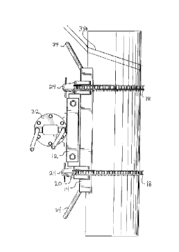
FIGURE 1 is a side elevation view of an apparatus for
removing contaminants from the interior of pipe constructed in
accordance with the teachings of the present invention, secured
to a pipe.
FIGURE 2 is a top plan view, in section, of the apparatus
illustrated in FIGURE 1.


DE~ATT-~n DESCRIPTION OF THE rK~nK~ EMBODIMENT

The preferred embodiment, an apparatus for removing
contaminants from the interior of pipe generally identified by
reference numeral 10, will now be described with reference to
FIGURES 1 and 2.

Referring to FIGURE 2, apparatus 10 includes a body 12
having a first side 14 and a second side 16. A pair of chains
18 are provided, each of which has a fixed end 20 and a free
end 22. Although chains are illustrated, it will be
appreciated that cables would be serve the intended function.
Fixed ends 20 of chains 18 are secured in spaced relation to
first side 14 of body 12. A pair of chain engaging clamps 24
are mounted on second side 16 of body 12 in spaced relation.
A pipe 26 is illustrated which has an exterior surface 28 and
an interior wall 30. Chains 18 are wrapped tightly in a loop
around exterior surface 28 of pipe 26. Chain engaging clamps
24 then clamp chains 18 adjacent to free ends 22, thereby
securing to body 12 to exterior surface 28 of pipe 26. A
vibration imparting drive motor 32 is mounted on body 12.
Typically, drive motor 32 will have an eccentric rotor (not
shown) so that operation of drive motor 32 causes vibration.
There are a variety of technologies suitable for drive motor
32, it may be electric, hydraulic, pneumatic or the like. For
convenience, it is preferred that body 12 have spaced apart
lifting handles 34, so that body 12 may be lifted into
position.

21g702~
~_ 4
The use and operation of apparatus 10 will now be
described with reference to FIGURES 1 and 2 and the preferred
method. Pipe 26 is illustrated having sand and clay
contaminants 36 clinging to interior wall 30. Fir~tly, secure
body 12 of apparatus 10 to exterior surface 28 of pipe 26.
This is accomplished by wrapping chains 18 tightly in a loop
around exterior surface 28 of pipe 26. Chain engaging clamps
24 are used to clamp chains 18 adjacent to free ends 22,
thereby securing to body 12 to exterior surface 28 of pipe 26.
Secondly, suspending pipe 26 on a line 38. By suspending pipe
26 on line 38, pipe 26 is kept clear of any surface that might
dampen vibration. Thirdly, activate drive motor 32 to vibrate
pipe 26 until contA~;nAnts 36 become dislodged.

It will be apparent to one skilled in the art that
modifications may be made to the illustrated embodiment without
departing from the spirit and scope of the invention as
hereinafter defined in the Claims.

Representative Drawing
A single figure which represents the drawing illustrating the invention.
Administrative Status

For a clearer understanding of the status of the application/patent presented on this page, the site Disclaimer , as well as the definitions for Patent , Administrative Status , Maintenance Fee  and Payment History  should be consulted.

Administrative Status

Title Date
Forecasted Issue Date 1999-01-19
(22) Filed 1997-02-07
Examination Requested 1997-02-07
(41) Open to Public Inspection 1997-03-07
(45) Issued 1999-01-19
Reissued 2000-08-22
Expired 2017-02-07

Abandonment History

There is no abandonment history.

Payment History

Fee Type Anniversary Year Due Date Amount Paid Paid Date
Request for Examination $200.00 1997-02-07
Application Fee $0.00 1997-02-07
Final Fee $150.00 1998-10-15
Maintenance Fee - Application - New Act 2 1999-02-08 $50.00 1998-11-03
Maintenance Fee - Patent - New Act 3 2000-02-07 $50.00 1999-11-08
Reissue a patent $800.00 2000-06-13
Maintenance Fee - Patent - New Act 4 2001-02-07 $50.00 2000-11-14
Maintenance Fee - Patent - New Act 5 2002-02-07 $75.00 2001-11-23
Maintenance Fee - Patent - New Act 6 2003-02-07 $75.00 2003-02-03
Maintenance Fee - Patent - New Act 7 2004-02-09 $75.00 2003-11-26
Maintenance Fee - Patent - New Act 8 2005-02-07 $75.00 2003-11-26
Maintenance Fee - Patent - New Act 9 2006-02-07 $75.00 2003-11-26
Maintenance Fee - Patent - New Act 10 2007-02-07 $100.00 2003-11-26
Maintenance Fee - Patent - New Act 11 2008-02-07 $100.00 2003-11-26
Maintenance Fee - Patent - New Act 12 2009-02-09 $125.00 2009-01-14
Maintenance Fee - Patent - New Act 13 2010-02-08 $125.00 2009-01-14
Maintenance Fee - Patent - New Act 14 2011-02-07 $125.00 2009-01-14
Maintenance Fee - Patent - New Act 15 2012-02-07 $225.00 2009-01-14
Maintenance Fee - Patent - New Act 16 2013-02-07 $225.00 2009-01-14
Maintenance Fee - Patent - New Act 17 2014-02-07 $225.00 2009-01-14
Maintenance Fee - Patent - New Act 18 2015-02-09 $225.00 2009-01-14
Maintenance Fee - Patent - New Act 19 2016-02-08 $225.00 2009-01-14
Owners on Record

Note: Records showing the ownership history in alphabetical order.

Current Owners on Record
SEDORE, RONALD STEPHEN
Past Owners on Record
None
Past Owners that do not appear in the "Owners on Record" listing will appear in other documentation within the application.
Documents

To view selected files, please enter reCAPTCHA code :


To view images, click a link in the Document Description column. To download the documents, select one or more checkboxes in the first column and then click the "Download Selected in PDF format (Zip Archive)" or the "Download Selected as Single PDF" button.

List of published and non-published patent-specific documents on the CPD .

If you have any difficulty accessing content, you can call the Client Service Centre at 1-866-997-1936 or send them an e-mail at CIPO Client Service Centre.


Document
Description 
Date
(yyyy-mm-dd) 
Number of pages   Size of Image (KB) 
Cover Page 1998-08-19 1 37
Claims 2000-06-13 2 74
Cover Page 2000-06-08 1 36
Representative Drawing 2000-07-25 1 9
Description 1998-03-18 4 166
Abstract 1998-03-18 1 11
Cover Page 1998-03-18 1 15
Representative Drawing 1998-08-19 1 10
Representative Drawing 1998-11-23 1 10
Cover Page 1998-11-23 1 37
Claims 1998-08-17 2 37
Claims 1998-03-18 2 35
Drawings 1998-03-18 2 47
Cover Page 2000-07-27 1 38
Prosecution-Amendment 2000-08-22 2 2
Prosecution-Amendment 2000-07-19 1 33
Fees 2003-02-03 1 27
Correspondence 2003-07-24 2 66
Correspondence 2003-07-31 1 13
Correspondence 2003-07-31 1 17
Fees 2003-11-26 1 28
Correspondence 1998-10-15 1 44
Fees 1998-11-03 1 37
Prosecution-Amendment 2000-06-13 7 253
Correspondence 2000-06-21 1 1
Correspondence Related to Formalities 1997-04-23 1 31
Office Letter 1997-03-11 1 32
Office Letter 1997-05-13 1 43
Office Letter 1997-06-19 1 43
Prosecution Correspondence 1998-07-20 3 136
Examiner Requisition 1998-01-23 2 69
Prosecution Correspondence 1997-10-30 4 142
Examiner Requisition 1997-06-27 3 103
Prosecution Correspondence 1997-02-07 8 230
Correspondence 2009-02-06 2 56
Fees 2009-01-14 1 33