Language selection

Search

Patent 2197129 Summary

Third-party information liability

Some of the information on this Web page has been provided by external sources. The Government of Canada is not responsible for the accuracy, reliability or currency of the information supplied by external sources. Users wishing to rely upon this information should consult directly with the source of the information. Content provided by external sources is not subject to official languages, privacy and accessibility requirements.

Claims and Abstract availability

Any discrepancies in the text and image of the Claims and Abstract are due to differing posting times. Text of the Claims and Abstract are posted:

  • At the time the application is open to public inspection;
  • At the time of issue of the patent (grant).
(12) Patent: (11) CA 2197129
(54) English Title: METHOD AND APPARATUS FOR SWITCHING SPREAD SPECTRUM/CODE DIVISION MULTIPLE ACCESS MODULATED BEAMS
(54) French Title: METHODE ET APPAREIL DE COMMUTATION DE FAISCEAUX MODULES A SPECTRE ETALE OU A ACCES MULTIPLE PAR DIFFERENCE DE CODE
Status: Deemed expired
Bibliographic Data
(51) International Patent Classification (IPC):
  • H04J 13/00 (2011.01)
  • H04B 7/216 (2006.01)
  • H04Q 11/00 (2006.01)
  • H04B 1/69 (2006.01)
(72) Inventors :
  • ERVING, RICHARD HENRY (United States of America)
  • GERAKOULIS, DIAKOUMIS PARISSIS (United States of America)
(73) Owners :
  • AT&T CORP. (United States of America)
(71) Applicants :
  • AT&T CORP. (United States of America)
(74) Agent: KIRBY EADES GALE BAKER
(74) Associate agent:
(45) Issued: 2000-04-25
(22) Filed Date: 1997-02-10
(41) Open to Public Inspection: 1997-10-23
Examination requested: 1997-02-10
Availability of licence: N/A
(25) Language of filing: English

Patent Cooperation Treaty (PCT): No

(30) Application Priority Data:
Application No. Country/Territory Date
635,163 United States of America 1996-04-23

Abstracts

English Abstract


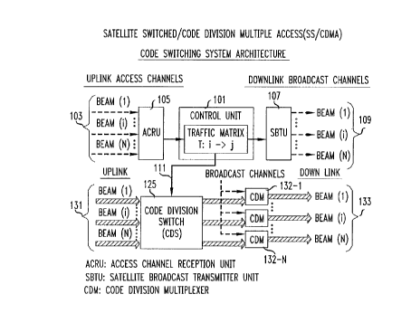
Switching of traffic channels within spread spectrum beams is
performed in a satellite without buffering of the individual signals. Individualsatellite beams carrying spread spectrum user RF signals from a plurality of
customer premise equipments are received by radio receivers of a satellite switch
and downconverted to IF signals. Traffic channel recovery is performed
immediately after the down conversion and digital encoding and decoding is
performed to route each channel to an appropriate outbound satellite beam. Traffic
channel recovery is by despreading and filtering followed by respreading to uniquely
identify each user signal so it may be recovered at its end destination. Furtherspreading uniquely identifies the user signal with an outbound satellite beam going
to the intended destination of the user signal.


French Abstract

La commutation des canaux de trafic dans les faisceaux à spectre étalé est effectuée dans un satellite sans mise en mémoire tampon des signaux individuels. Les divers faisceaux des satellites qui transmettent les signaux RF à spectre étalé provenant d'une pluralité d'installations d'abonné sont reçus par les récepteurs radio d'un commutateur de satellite et sont convertis en signaux FI avec abaissement de fréquence. Le recouvrement des signaux transmis par le canal est effectué immédiatement après la conversion et un codage et un décodage numériques sont effectués pour transmettre les signaux de chaque canal sur un faisceau approprié émis par le satellite. Le recouvrement des signaux transmis par le canal se fait par un désétalement et un filtrage suivis par un réétalement pour identifier chaque signal d'utilisateur en vue de le recouvrer à sa destination après sa transmission sur le faisceau du satellite.

Claims

Note: Claims are shown in the official language in which they were submitted.


-5-


Claims:

1. A method of switching a channel from an incoming spread spectrum beam to
an outgoing spread spectrum beam, comprising the steps of:
coding each channel in the incoming spread spectrum beam in a manner to
enhance channel separation and reduce interference between individual channels
contained
within the beams and recovering individual traffic channels by application of
a user specific
pseudo random beam code;
summing all recovered traffic channels onto an overspread bus;
directing and combining recovered individual traffic channels from the
overspread bus into outgoing spread spectrum beams each having a destination
in common
with the traffic channels it contains.

2. A method of switching a channel from an incoming spread spectrum beam to
an outgoing spread spectrum beam as claimed in claim 1:
wherein the step of coding each channel includes overspreading with
application of an overspreading code.

3. A method of switching a channel from an incoming spread spectrum beam to
an outgoing spread spectrum beam as claimed in claim 1:
wherein the step of coding each channel includes IF filtering of the traffic
channel during traffic channel recovery.

4. A method of switching a channel from an incoming spread spectrum beam to
an outgoing spread spectrum beam as claimed in claim 1:
wherein the step of directing and combining includes a step of mixing with a
Walsh code and summing the mixed signal for a code word length.

5. A method of switching a channel from an incoming spread spectrum beam to
an outgoing spread spectrum beam as claimed in claim 4:


-6-


wherein the step of directing and combining includes the step of recovering
individual outgoing beams by application of a despreading code in a mixer.

6. A switching system for switching a channel from an incoming spread
spectrum beam to an outgoing spread spectrum beam, comprising:
frequency conversion circuitry connected for receiving incoming spread
spectrum RF beams and for converting them to IF beams;
mixer circuitry for despreading the IF beams with a pseudo-random beam code;
a plurality of traffic channel recovery circuits connected to receive the
spread
IF beams and operating to recover individual traffic channels; and the traffic
channel
recovery circuit including:
a plurality of destination selecting mixers each connected to receive the
traffic
channel recovery circuit output and applying an overspreading code to the
traffic channels;
means for forming outgoing spread spectrum beams having destinations in
common with traffic channels contained within.

7. A switching system for switching a channel from an incoming spread
spectrum beam to an outgoing spread spectrum beam, as claimed in claim 6,
comprising:
wherein the plurality of destination selecting mixers include:
a first destination selection mixer for identifying the user within the
destination
beam; and
a second destination selection mixer for identifying the output beams and
their
destinations.

8. A switching system for switching a channel from an incoming spread
spectrum beam to an outgoing spread spectrum beam, as claimed in claim 6,
comprising:
the traffic channel recovery circuit further including:
an overspreading mixer for overspreading outgoing traffic channels.


9. A switching system for switching a channel from an incoming spread
spectrum beam to an outgoing spread spectrum beam, as claimed in claim 6,
comprising:
wherein the outgoing beam is mixed in the destination selecting mixer with an
orthogonal code and processed by an integrator to recover the outgoing channel
for the length
of an overspreading code.

10. A switching system for switching in the sky a channel from an incoming
spread spectrum RF beam to an outgoing spread spectrum RF beam,
CHARACTERIZED BY:
frequency conversion circuitry connected for receiving incoming spread
spectrum RF beams and for downconverting them to IF beams;
means for applying a pseudo-random beam code g n to identify individual
channels;
a plurality of traffic channel recovery circuits connected to receive a
plurality
of spread IF beams and by further despreading and spreading by orthogonal
codes recovering
identities of individual traffic channels; the traffic channel recovery
circuit including:
circuitry for despreading IF beams with the orthogonal code to prevent
overlapping of channels within a beam;
circuitry for integrating the despread IF beams to recover traffic channels
and
reduce their sample rate to a symbol rate;
circuitry respreading the IF beam with the orthogonal code to uniquely
identify
channel users; and
circuitry for respreading the IF beam by a pseudo-random beam code to
identify the outgoing beam code carrying the channel to its destination.

11. A switching system for switching in the sky a channel from an incoming
spread spectrum RF beam to an outgoing spread spectrum RF beam, as claimed in
claim 10,
further comprising:
circuitry for overspreading the output beam to separate different output
beams.


-8-


12. A switching system for switching in the sky a channel from an incoming
spread spectrum RF beam to an outgoing spread spectrum RF beam, as claimed in
claim 10,
further comprising:
the means for applying including a mixer circuit for despreading the IF beams
with the pseudo-random beam code g n.


Description

Note: Descriptions are shown in the official language in which they were submitted.


2197 ) 29
-, -
Method And Apparatus For Switching
Spread Spectrum/Code Division Multiple Access
Modulated Beams
Field of the Invention
This invention relates to switching apparatus and methods to be used in
wired and/or wireless digital telecommunication systems for message switching.
It
is particularly concerned with the switching of spread spectrum/CDMA modulated
beams carrying traffic channels from a specific source to a specific
destination.
Background of the Invention
Digital switching of spread spectrum/CDMA digital telecommunication
signals has previously been limited to circuit and packet switching. Packet
type
switching is batch transmission signaling and generally requires the use of a
buffer
memory somewhere in the transmission process. The switching (i.e., CDMA
message multiplexing) of end-to-end CDMA complete message signals, without the
buffering requirement, has been considered to have complexity sufficient to
render it
impractical and uneconomical. In some instances a CDMA beam may be redirected,
but the individual traffic channels included within each uplink beam are left
undisturbed in a corresponding downlink CDMA beam. Uplink CDMA beams are
redirected and become a downlink beam, but include the same traffic channels.
So
traffic channels must have common destinations with the common redirected CDMA
beam in which they are included.
In some instances the handling of CDMA packet beams requires the
conversion of the CDMA traffic channels to baseband frequencies for switching
and
redirection processes to occur.
Summary of the Invention
Therefore in accord with the invention a method and apparatus for
switching traffic channels between uplink and downlink spread spectrum/CDMA
modulated beams is disclosed as claimed in the claims. It particularly
concerns
CDMA information traffic channel (i.e.,message) switching in which a total
aggregate information signal is switched at IF frequency without memory
buffering
required in the process.


CA 02197129 1999-06-30
-2-
In a particular embodiment of the invention individual satellite beams
carrying
spread spectrum user RF signals from a plurality of customer premise
equipments are
received by radio receivers of a satellite switch and downconverted to IF
signals. Traffic
channel recovery is performed immediately after the down conversion and
digital encoding
and decoding is performed to route each channel to an appropriate outbound
satellite beam.
Traffic channel recovery is by despreading and filtering followed by
respreading to uniquely identify each user signal so it may be recovered at
its end destination.
Further spreading uniquely identifies the user signal with an outbound
satellite beam going to
the intended destination of the use signal.
In accordance; with one aspect of the present invention there is provided a
method of switching a channel from an incoming spread spectrum beam to an
outgoing
spread spectrum beam, comprising the steps of coding each channel in the
incoming spread
spectrum beam in a manner to enhance channel separation and reduce
interference between
individual channels contained within the beams and recovering individual
traffic channels by
application of a user specific pseudo random beam code; summing all recovered
traffic
channels onto an overspread bus; directing and combining recovered individual
traffic
channels from the overspread bus into outgoing spread spectrum beams each
having a
destination in common with the traffic channels it contains.
In accordance with another aspect of the present invention there is provided a
switching system for switching a channel from an incoming spread spectrum beam
to an
outgoing spread spectrum beam, comprising: frequency conversion circuitry
connected for
receiving incoming spread spectrum RF beams and for converting them to IF
beams; mixer
circuitry for despreading th<; IF beams with a pseudo-random beam code; a
plurality of traffic
channel recovery circuits connected to receive the spread IF beams and
operating to recover
individual traffic channels; .and the traffic channel recovery circuit
including: a plurality of
destination selecting mixers each connected to receive the traffic channel
recovery circuit
output and applying an overspreading code to the traffic channels; means for
forming
outgoing spread spectrum beams having destinations in common with traffic
channels
contained within.


CA 02197129 1999-06-30
-2a-
Brief Description of the Drawings
FIG. 1 is a block schematic of a code switching system architecture;
FIG. 2 is a block schematic of a code division switch;
FIG. 3 is a block schematic of a traffic channel recovery circuit which is a
sub-
component of the code division switch;
FIG. 4 is a schematic of the matrix arrangement for directing traffic channels
to
the proper destination directed outgoing CDMA beam.
Detailed Description
A code switching architecture, such as shown in FIG. 1, includes a control
unit
101 having memory storage; for a traffic matrix relating uplink sources to
intended downlink
destinations. Uplink access channels 103, which may comprise a plurality of
uplink data and
access CDMA beams 1 through N, are directed to an Access Channel Reception
Unit 105 for
processing and for whose output is directed to the control unit 101. The
output of the control
unit 101 is applied to a Satellite Broadcast Transmitter Unit 107 where it
supplies the
downlink broadcast data and access channels over the CDMA beams 109. A second
output of
the control unit is applied, via lead 111, to a code division switch 125.
Code division switch 125 accepts a plurality of bearer CDMA modulated RF
beams 131, extracts the individual traffic channels contained within each beam
and combines
them into outgoing beams having a destination in common with the traffic
channels it
contains. The destination traffic channels are inserted into downlink CDMA
beams 133, in
accord with broadcast channels applied to CDMA multiplexers 132-1 to 132-N,
for
transmission to specific downlink destinations.


v..r . 2197129
-3-
While a satellite application, using an air interface is shown as an
illustrative embodiment, the invention is not limited to satellite
communication
systems. The invention is equally applicable to terrestrial communication
systems
and to systems using wired and optical connections.
In FIG. 2 a plurality of incoming spread spectrum RF beams 201-1 to
201-N are all applied to downconversion units 202-1 to 202-N which convert the
beams to IF. The downconverted IF beams 203-1 to 203-N are spread with a
pseudo-random beam code g" applied to the mixer circuits 204-1 to 204-N to
identify the individual traffic channels. In the illustrative embodiment g"
may be a
Gold code with slight interference between adjacent satellite beams. The coded
signals, from each mixer, are applied to buses 205-1 to 205-N which are
coupled to
several traffic channel recovery circuits 206-1-1 to 206-1-1 and 206-N-1 to
206-N-1.
The individual traffic channels are recovered from each of the IF beams by
despreading and respreading techniques as described with respect to FIG. 3.
The
output of all the traffic channel recovery circuits are summed in common in
the
summer 207 and applied in common to the overspread bus 208 which carries the
overspread signals from the traffic channel recovery circuits 206-1-1 to 206-1-
L to
206 -N-1 to 206-N-L. to the mixers 209-1 through 209-N.
Outputs of overspread beams from the bus 208 are recovered by
despreading with a Walsh code W ~ in the mixers 209-1 to 209-N to prevent
overlap
of the adjacent satellite beams. By integrating (i.e., analog) or accumulating
(i.e.,
digital) the spread beam in integrators 210-1 to 210-N to recover the signal
over the
code length in order to generate the outgoing spread spectrum beams 211-1 to
211-N
having destinations in harmony with the channels they contain.
A suitable traffic channel recovery circuit shown in the FIG 3 accepts
the output of one of buses 205-N and applies it to a mixer 303 where the
traffic
channel, in the illustrative embodiment, is despread with a Walsh code W ~ to
keep
traffic channels from overlapping within a beam. This despread traffic channel
is
integrated in the integrator 304 to reduce the sample rate to the symbol rate.
Subsequently the integrated signal is filtered by the IF filter 306. If the
despreading
is done digitally, the filtering step is incorporated in the despreading
operation. The
filtered traffic channel is respread by an output beam Walsh code W na in the
mixer
307 to uniquely identify the user. and further respread by a downlink pseudo-
random beam code in the mixer 309 to identify the outgoing beam transporting
the
traffic channel. The output of mixer 309 is overspread with an orthogonal
Walsh
code W k in the mixer 311 to separate the output beams on the overspread bus.
The


' '~ 2197129
-4-
output of mixer 311 for application to the summing circuit is as shown in FIG.
1.
A matrix is used, in the illustrative embodiment, for coupling traffic
channels of an incoming CDMA beam to an outgoing CDMA beam. An illustrative
matrix (for three beams) which may be used in the control unit for directing
uplink
traffic channels to downlink beams is shown in the FIG. 4 and may be contained
n
the control unit as part of a stored program. As shown the columns are
identified
with the downlink CDMA beams and the rows are identified with the uplink CDMA
beams. Each uplink and downlink CDMA contains a plurality of user traffic
incoming channels U n + U m + --- + U P and outgoing U a + U b + --- + U ~,
respectively. The matrix entries indicate the codes to be used for the uplink
and
downlink traffic channels. This assures that the downlink traffic channels are
included in the desired downlink beam.

Representative Drawing
A single figure which represents the drawing illustrating the invention.
Administrative Status

For a clearer understanding of the status of the application/patent presented on this page, the site Disclaimer , as well as the definitions for Patent , Administrative Status , Maintenance Fee  and Payment History  should be consulted.

Administrative Status

Title Date
Forecasted Issue Date 2000-04-25
(22) Filed 1997-02-10
Examination Requested 1997-02-10
(41) Open to Public Inspection 1997-10-23
(45) Issued 2000-04-25
Deemed Expired 2017-02-10

Abandonment History

There is no abandonment history.

Payment History

Fee Type Anniversary Year Due Date Amount Paid Paid Date
Request for Examination $400.00 1997-02-10
Registration of a document - section 124 $100.00 1997-02-10
Application Fee $0.00 1997-02-10
Maintenance Fee - Application - New Act 2 1999-02-10 $100.00 1998-12-17
Maintenance Fee - Application - New Act 3 2000-02-10 $100.00 1999-12-14
Final Fee $300.00 2000-02-03
Maintenance Fee - Patent - New Act 4 2001-02-12 $100.00 2001-01-18
Maintenance Fee - Patent - New Act 5 2002-02-11 $150.00 2002-01-07
Maintenance Fee - Patent - New Act 6 2003-02-10 $150.00 2003-01-06
Maintenance Fee - Patent - New Act 7 2004-02-10 $150.00 2003-12-16
Maintenance Fee - Patent - New Act 8 2005-02-10 $200.00 2005-01-10
Maintenance Fee - Patent - New Act 9 2006-02-10 $200.00 2006-01-09
Maintenance Fee - Patent - New Act 10 2007-02-12 $250.00 2007-01-05
Maintenance Fee - Patent - New Act 11 2008-02-11 $250.00 2008-01-09
Maintenance Fee - Patent - New Act 12 2009-02-10 $250.00 2009-01-09
Maintenance Fee - Patent - New Act 13 2010-02-10 $250.00 2010-01-07
Maintenance Fee - Patent - New Act 14 2011-02-10 $250.00 2011-01-25
Maintenance Fee - Patent - New Act 15 2012-02-10 $450.00 2012-01-19
Maintenance Fee - Patent - New Act 16 2013-02-11 $450.00 2013-01-18
Maintenance Fee - Patent - New Act 17 2014-02-10 $450.00 2014-01-22
Maintenance Fee - Patent - New Act 18 2015-02-10 $450.00 2015-01-19
Owners on Record

Note: Records showing the ownership history in alphabetical order.

Current Owners on Record
AT&T CORP.
Past Owners on Record
ERVING, RICHARD HENRY
GERAKOULIS, DIAKOUMIS PARISSIS
Past Owners that do not appear in the "Owners on Record" listing will appear in other documentation within the application.
Documents

To view selected files, please enter reCAPTCHA code :


To view images, click a link in the Document Description column. To download the documents, select one or more checkboxes in the first column and then click the "Download Selected in PDF format (Zip Archive)" or the "Download Selected as Single PDF" button.

List of published and non-published patent-specific documents on the CPD .

If you have any difficulty accessing content, you can call the Client Service Centre at 1-866-997-1936 or send them an e-mail at CIPO Client Service Centre.


Document
Description 
Date
(yyyy-mm-dd) 
Number of pages   Size of Image (KB) 
Cover Page 1997-12-04 1 62
Drawings 1997-05-14 4 76
Abstract 1997-05-14 1 23
Cover Page 1997-05-14 1 19
Description 1997-05-14 4 184
Claims 1997-05-14 3 120
Cover Page 2000-03-27 2 74
Claims 1999-06-30 4 134
Description 1999-06-30 5 228
Representative Drawing 1997-12-04 1 12
Representative Drawing 2000-03-27 1 17
Assignment 1997-02-10 9 245
Prosecution-Amendment 1999-03-31 2 5
Prosecution-Amendment 1999-06-30 7 277
Correspondence 2000-02-02 1 37