Note: Descriptions are shown in the official language in which they were submitted.
- 21 ~7257
TITLE: AN OPEN-END FASTENER
This invention is related to an improved fastener and
in particular to an open-end fastener which can be used as
an electrical wire fastener and a suspension hook.
It has been found that the conventional fasteners for
securing electrical wires are unsatisfactory in use and
suffer from the following drawbacks:
1. The receiving space of the fastener is fixed and
so it is necessary to produce a number of fasteners with
various sizes so as to be able to receive electrical wires
of different diameters.
2. Once the electrical wire is fixed on the wall by
the fastener, the electrical wire cannot be disengaged
from the fastener unless the fastener is pulled out of the
wall.
3. In case the electrical wire is inadvertently
pulled, the fastener will be pulled out of the wall.
4. It is necessary to hold a hammer in one hand and
press an electrical wire with the fastener in the other in
securing the electrical wire on the wall thereby causing
- 2~ q7257
much inconvenience in operation.
Regarding the conventional suspension hooks, they
also suffer from the following disadvantages:
1. If the hook portion is of a large size~ it will be
easily catch hold of something thus causing much
inconvenience in use. If the hook portion is of a small
size, it cannot be used for hanging heavy objects.
2. The hook portion is open and so it cannot hold the
object securely.
Therefore, it is an object of the present invention
to provide an improved fastener which can obviate and
mitigate the above-mentioned drawbacks.
This invention is related to an improved fastener.
It is the primary object of the present invention to
provide an open-end fastener which can keep one or more
electrical wires or the like in place.
It is another object of the present invention to
provide an open-end fastener which will not disengage from
the wall even when the electrical wire is inadvertently
pulled out from the fastener.
- 21 97257
It is still another object of the present invention
to provide an open-end fastener which can be used as a
suspension hook.
It is still another object of the present invention
to provide an open-end fastener which is easy to use.
It is a further object of the present invention to
provide an open end fastener which is simple in
construction.
The foregoing objects and summary provide only a
brief introduction to the present invention. To fully
appreciate these and other objects of the present
invention as well as as the invention itself, all of which
will become apparent to those skilled in the art, the
following detailed description of the invention and the
claims should be read in conjunction with the accompanying
drawings. Throughout the specification and drawings
identical reference numberals refer to identical or
similar parts.
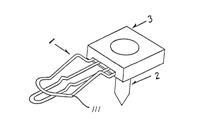
FIG. 1 is a perspective view of the present
invention;
21 q7257
FIG. 2A is a top view of the clip;
FIG. 2B is a side view of the clip;
FIG. 2C is a perspective view of the clip;
FIG. 3 illustrates how electrical wires are forced
through the entrance of the clip;
FIG. 4 illustrates how the electrical wires are kept
in position;
FIG. 5 illustrates how the clip is fastened on the
wall by the nail;
FIG. 5A illustrates the first area of the clip for
the passage of the pointed pin of the nail;
FIG. 5B illustrates the second area for receiving the
flat head of the nail;
FIGS. 6A, 6B and 6C are the top, front and side views
of the plastic cap;
FIG. 7 is an exploded view of the present invention;
FIGS. 8, 8A and 8B illustrate electrical wires which
are kept on the wall by the present invention;
FIGS. 9 and 9A illustrate how to use the present
invention as a suspending hook;
21 97257
FIG. 10 is a perspective view of a second preferred
embodiment of the present invention;
FIG. lOA is a side view of the second preferred
embodiment;
FIGS. 11, llA and llB are the perspective, top and
side views of a plastic cap according to the third
embodiment of the present invention;
FIG. 12 is a perspective view of the clip according
to the third preferred embodiment;
FIG. 13 is a side view of the fastener according to
the third preferred embodiment; and
FIG. 14 is an exploded view of the fastener according
to the third preferred embodiment.
For the purpose of promoting an understanding of the
principles of the invention, reference will now be made to
the embodiment illustrated in the drawings. Specific
language will be used to describe same. It will,
nevertheless, be understood that no limitation of the
scope of the invention is thereby intended, such
alterations and further modifications in the illustrated
- 21 97257
device, and such further applications of the principles of
the invention as illustrated herein being contemplated as
would normally occur to one skilled in the art to which
the invention relates.
With reference to the drawings and in particular to
FIGS. 1, 6A, 6B, 6C and 7, the open-end fastener for
electrical wires according to the present invention
basically comprises a clip 3, a nail 2 and a plastic cap
3. The plastic cap 3 is formed with a slot 33
horizontally extending therein, a vertical through hole 31
at the central portion and a circular recess 32 at the top
and concentric with and having a larger diameter than the
hole 31. The clip 3 has an end fitted into the horizontal
slot 33 of the plastic cap 3, while the nail 2 has a
pointed pin 21 adapted to be inserted through the center
hole 31 and a flat head 22 adapted to be received in the
circular recess 32.
Referring to FIGS. 2A, 2B, 2C, 3 and 4, the clip 1 is
an integral wire member bent to form an upper front
portion 111, a lower front portion 112, an upper
21 97257
intermediate portion 121, a lower intermediate portion
122, an upper rear portion 131 and a lower rear portion
132. Between the upper and lower intermediate portions
121 and 122 there is a space 12. Between the upper front
portion 111 and the lower front portion 112 there is an
entrance 11. Hence, the electrical wires 41 can be forced
through the entrance 11 into the space 12 and kept in
place by the restoring force of the upper front portion
111 .
As shown in FIGS. 5, 5A and 5B, the upper rear
portion 131 and the lower rear portion 132 are connected
to each other and there are a first area 133 and a second
area 134 at the rear portion of the clip 1. The first
area 133 is designed for the passage of the pointed pin 21
of the nail 2, while the second area 134 is to be pressed
against by the flat head 22 of the nail 2, so that the
clip 1 can be firmly fastened on the wall.
As the fastener according to the present invention is
has an open-end clip 1, so that even the electrical
wires 41 kept in position by the open-end fasteners ~see
21 97257
FIGS. 8, 8A and 8~) are inadvertently pulled out of the
fasteners, the fasteners will remain on the wall and the
electrical wires 41 can be easily forced through the
entrance 11 into the space 12 of the clip 1 thereby keeping
the electrical wires 41 in position again. In addition,
the open-end clip 1 can be used as a suspension hook, as
shown in FIG. 9 and 9A.
FIGS. 10 and lOA illustrate a second preferred
embodiment of the present invention. As shown, the lower
front portion 112' is connected with the lower
intermediate portion 122' on the same horizontal plane and
the lower intermediate portion 122' is bent upwardly to
form an upper intermediate portion 121' to form a space
12'. Hence, the nail 2' can go directly through the front
end of the clip 1' to fix the clip 1' on the wall 5' and
this embodiment does not need a plastic cap 2.
FIGS. 11, llA, 11~, 12, 13 and 14 illustrate a third
preferred embodiment of the present invention. As shown,
the plastic cap 3 is formed with a main groove 330 at the
bottom, a vertical through hole 310 at the central
21 97257
portion, a circular recess 320 at the top and concentric
with and having a larger diameter than the hole 310, and
two opposite grooves 340 at two sides of the bottom
extending inwardly to be in communication with the main
groove 330. The clip 100 includes two legs 1120 each
having a outwardly extending lug 1350 at the end so that
when the clip 100 is engaged with plastic cap 3, the legs
1120 are fitted in the main groove 33 and their lugs 1350
engaged with the grooves 340 of the plastic cap 3.
Further, the clip 100 includes an upper portion 1110 which
will provide a passage 110 for an electrical wire (not
shown) to go into the space 120 between the upper U-shaped
portion 1110 and the legs 1120.
It will be understood that each of the elements
described above, or two or more together may also find a
useful application in other types of methods differing
from the type described above.
While certain novel features of this invention have
been shown and described and are pointed out in the
annexed claim, it is not intended to be limited to the
21 97257
-
details above, since it will be understood that various
omissions, modifications, substitutions and changes in the
forms and details of the device illustrated and in its
operation can be made by those skilled in the art without
departing in any way from the spirit of the present
invention.
Without further analysis, the foregoing will so fully
reveal the gist of the present invention that others can,
by applying current knowledge, readily adapt it for
various applications without omitting features that, from
the standpoint of prior art, fairly constitute essential
characteristics of the generic or specific aspects of this
invention.