Note: Descriptions are shown in the official language in which they were submitted.
d
219'342
SPECIFICATION
TITLE OF INVENTION
CDMA DEMODULATING APPARATUS
TECHNICAL FIELD
The present invention relates to a code division
multiple access (CDMA) demodulating apparatus used
for receiving signals of a CDMA system using spread
spectrum, and more specifically to a CDMA
demodulating apparatus suitable for a mobile
communication system which uses a cellular
configuration.
BACKGROUND ART
DS (Direct Sequence) - CDMA is a system in which
a plurality of users carry out communications using
a same frequency band, and each user is identified
by a spreading code. As a spreading code for each
user, a spreading code such as Gold code is used.
Interference signal power of another user is a
reciprocal of average spreading factor (PG) in the
despreading process of a receiver. However, each
- 1 -
219~3~~
user, especially under asynchronous environment in
ascendant mobile communications, is subject to
momentary variation, short section variation, and
distance variation due to independent fading.
Therefore, to satisfy a predetermined reception
quality determined by the system by each user at the
receiving side, it is necessary to control the
transmission power to achieve a constant SIR
(Signal-to-Interference Ratio) in the receiver input
at the base station. Here, SIR is a ratio of the
reception signal power at the user of the desired
wave to the interference signal power received from
another user. However, even though the transmission
power control is perfect, and the SIR in the base
station receiver input is maintained at a constant
value, under multipath environment of mobile
communications, spreading codes will never quadrate
completely with each other. Therefore, the user is
subject to interference due to cross-correlation of
the power of a reciprocal of spreading factor at an
average per one of other users.
As shown above, since the interference signal
level increases with increasing number of users
communicating in the same frequency band, to
increase the user capacity per cell, an interference
- 2 -
219'34?
canceling technique to reduce interference from
other users is required.
As interference canceling techniques, a multi-
user type interference canceler and a single user
type interference canceler are known. The multi-
user type interference canceler not only demodulates
a desired wave signal of its own channel, but also
demodulates a signal of another user using spreading
code information and reception signal timing of the
other user. The single user type interference
canceler, on the other hand, uses only the spreading
code of own channel to minimize an average cross-
correlation and noise component from the other user.
The multi-user type canceler includes a linear
processing type (decorrelator or the like) and a
nonlinear processing type. The decorrelator
calculates mutual correlation of the spreading code
of own channel and all other spreading codes of
receiver input to determine an inverse matrix
composed of the cross-correlation, and the cross-
correlation is canceled by compensating for the
output signal of a matched filter using this inverse
matrix. Where K is a number of users, and Lk is a
number of reception paths to individual users,
dimension Dm of the decorrelator matrix is given by
the following equation.
- 3 -
~l9'~~4~
[Equation]
K
Dm = (2M + 1) x ~ Lk
k=1
Therefore, realization of the above technique
becomes difficult as the number of users increases,
which increases the circuit scale.
A nonlinear multi-user type interference
canceler is a replica reproduction type interference
canceler. This canceler demodulates interference
signal from other user's channel, decides it to
reproduce transmission information data replica,
calculates an interference signal replica of each
channel from this replica, and subtracts the
interference replica from the reception signal,
thereby demodulating the desired wave signal with
enhanced SIR.
Fig. 1 shows a replica reproduction type multi-
stage interference canceler (serial interference
canceler) proposed in the document "Serial
interference cancellation method for CDMA", IEE,
Electronics Letters Vol. 30, No. 19, pp. 1581-1582,
Sept. 1994.
In Fig. 1, the numeral 11 indicates a spread
signal, 12, 16 are delay units, 13, 17 are matched
- 4 -
~19~~~~
filters, 14, 18 are respreaders, and 15 is a
interference subtractor. The serial canceler
comprises interference canceling blocks in a
plurality of stages, connected in series, whereby
the interference canceling blocks of individual
stages carry out demodulation and generation of
interference signal replica by turns to M users to
be demodulated.
The receiver first rearranges the reception
signals in the order of reception signal level. For
explanation, serial numbers from 1 to M are assigned
to the rearranged signals, number 1 being assigned
to the highest reception signal level. The
interference canceling block of the first stage
makes despreading, demodulation and data decision by
the matched filter 13 on the reception signal of
number 1, and the resulting reproduction data is
referred to as D1~1~. The respreader 14 calculates
an interference signal replica S1~1~ of this channel
from the reproduction data D1~1~. The interference
subtractor 15 subtracts the interference signal
replica from a reception signal S passed through the
delay unit 16. The matched filter 17 makes
despreading, demodulation and data decision on the
signal obtained by the subtraction using the
spreading code replica of user 2 to obtain a
- 5 -
219'~~~~~
reproduction data D2(1) of user 2. The matched
filter input signal of user 2 is improved in SIR to
the extent that the interference signal replica S1(1)
of user 1 is subtracted as compared with direct
despreading from the reception signal S.
Similarly, to user 2, an interference signal
replica S2(1) is obtained from the reproduction data.
A matched filter input signal of user 3 is obtained
by subtracting interference signal replicas of users
1 and 2 from the reception signal S passed through
the delay unit. Using this procedure, for
subsequent users, the reception SIR can be further
enhanced. When despreading the reception signal of
M'th user, interference signal replicas S1(1) + S2(1)
+ ....SM-1~1) of a total of (M-1) users are
subtracted from the reception signal S to produce a
signal, thereby considerably improving the SIR over
the reception signal S. As a result, demodulated
signal of M'th channel is improved in reliability.
Using interference signal replicas S1(1), S2(1),
....., SM-1~1) of individual users estimated in the
first stage interference canceling block, similar
despreading, demodulation, data decision, and
respreading are carried out in the second stage
interference canceling block. For user 1,
interference signal replicas S2(1) + S3(1) + ..... +
- 6 -
~19~~42
SM~1~ other than of user 1 determined by the first
stage interference canceling block are subtracted
from the reception signal S to produce a signal of
improved SIR, and on this signal, despreading,
demodulation and data decision are carried out. To
other channels, similar processing is applied. That
is, a signal, obtained by subtracting interference
signal replicas in the first stage of channels other
than own channel from the reception signal S, is
subjected to respreading, demodulation, and data
decision, and from the reproduction data,
interference signal replicas Sy2~, 52~2~, .....,
SM~2~ of individual channels in the second stage
interference canceling block are determined.
Accuracy of the interference signal replicas in
the second stage interference signal canceling block
is improved compared with the interference signal
replicas in the previous stage. This is because
data reproduction is made based on the signal
obtained by subtraction of interference signal
replicas in the previous stage. By repeating serial
interference cancellation in several stages,
reliability of the reproduction data can be improved
even further.
~19~34~
Under mobile communication environment,
amplitude variation and phase variation occur due to
Rayleigh fading in association with variation in
relative positions between the mobile station and
base station. In the multi-stage type interference
canceler (serial interference canceler) shown in
Fig. 1, it is necessary to estimate the phase and
amplitude variations in the process of generating
the interference signal replicas. The channel
(phase; amplitude) estimation accuracy greatly
affects the reception characteristics of the multi-
stage type interference canceler, but realizability
thereof is not described in the above document. As
a method in which estimation of transmission path
variation under mobile communication environment is
added to the serial interference canceler of the
above document, there is another document: Fukazawa
et al., "Construction and characteristics of
interference canceler according to transmission path
estimation using a pilot signal", Proceedings of the
Electronic Information Communication Society, Vol.
J77-B-II No. 11, pp. 628-640, Nov. 1994.
Figs. 2A and 2B are block diagrams showing a
serial canceler shown in this document. Fig. 3
shows the channel structure of the method.
- g -
zm~~ ~z
In Figs. 2A and 2B, the numeral 21 indicates a
spreading code input terminal, 22 is a first stage
reproduction data output terminal of user 1, 23 is a
delay unit, 24 is a pilot channel transmission path
variation estimator, 25 is an interference
subtractor, 26 is a first stage interference
canceling block, 27 is a second stage interference
canceling block, 28 is a matched filter, 29 is a
transmission path compensator, 30 is a RAKE
combiner, 31 is data decision block, 32 is a signal
distributor, 33 is a transmission path variation
adder, and 34 is a respreader.
This system, as shown in Fig. 3, is provided
with a pilot channel having a known transmission
pattern parallel with the communication channel.
Transmission path estimation is made based on the
reception phase of the pilot channel. Further,
amplitude/phase estimation of the reception signal
of each path of each user is carried out based on
the transmission path estimation of the pilot
channel. Still further, using the amplitude/phase
estimation value, interference canceling of several
stages is carried out by the serial interference
canceling block to reproduce data of each user. In
this case, as in the previous document, individual
paths are ranked in the decreasing order of the sum
- 9 -
~19'~34~
of reception signal power. In the case of Figs. 2A
and 2B, the user 1 reception signal power is assumed
as to be the highest.
In the first stage interference canceling block,
demodulation is first carried out on user 1. That
is, each path of user 1 is despread by a matched
filter 28, in a transmission path variation
compensator 29, each path of user 1 is compensated
for phase variation according to the phase variation
of each path estimated with respect to the pilot
channel. Further, in the RAKE combiner 30, signals
of the phase variation compensated paths are phase
synthesized by a reception complex envelope curve of
individual paths. The phase synthesized signal is
decided by the data decision block 31 to obtain
reproduction data of user 1. The distributor 32
distributes the reproduction data replica according
to weighting at the RAKE combining, the transmission
path variation adder 33 gives a phase variation of
each path, and the respreader 34 makes respreading
by spreading code of each path to produce the
interference signal replica S1(1).
For user 2, the following processing is made.
First, a delay unit 35 delays the reception signal
S. The interference subtractor 25 subtracts the
interference signal replica S1~1~ of user 1 from the
- 10 -
~19'~342
delayed signal. The first stage interference
canceling block of user 2 carries out despreading.
phase compensation, RAKE combining, data decision,
and production of interference signal replica for
each path to the output signal of the interference
subtractor 25. In this case, the input signal of
the interference signal canceling block of user 2 is
improved in reception SIR to the extent that the
user 1 interference signal replicas are subtracted.
Similarly, reproduction data is estimated for each
user by the first stage interference canceling block
up to user M to obtain interference signal replicas.
The interference signal canceling block of
second stage carries out similar processing using
interference signal replicas S1 ( 1 ) , Sz ( 1 ) , . . . , SM ( 1 )
obtained by the interference signal canceling block
of the first stage. For example, the second stage
interference signal canceling block 27 (comprising
the components 28-34 of the first stage) of user 1
makes data demodulation by despreading the signal
obtained by subtracting the channel interference
signal replicas other than own channel from the
reception signal S delayed by delay unit 23.
A difference of the prior art method from the
method described in the previous document is the
following point. In the previous method, for user 2,
- 11 -
219'~~ 4~
for example, interference signal replicas S1(1) +
S3(1) + ... +SM(1) in the foregoing stage are used as
interference signal replicas of all paths. On the
other hand, in the method of this document, S1(2) is
used as an interference signal replica of user 1 in
the second stage. Compared with the estimated value
S1(1) in the foregoing stage, the estimated value
S1(2) in this stage is higher in reliability.
Therefore, the accuracy of the desired wave signal
obtained by subtracting the interference replicas.
and reliability of decision data obtained by
demodulation are also improved.
However, in this method, a pilot channel is
provided in parallel with the communication channel
for each user, and a channel estimated in the pilot
channel is used in each stage of interference
canceling block. In this case, since channel
estimation in the pilot channel is carried out
independent of the interference canceling loop, to
estimate channel (phase, amplitude) variation in
high accuracy, it has been necessary to make
averaging over a very long time (using many pilot
symbols). For averaging using such numerous pilot
symbols, it is assumed that channel estimation
values in this period be approximately constant,
therefore, it is limited to be applied to an
- 12 -
219'~3~?
environment of fast channel variation (high fading
frequency). When fading is fast, averaging is
possible only in a range where the values can be
regarded as constant, it is therefore impossible to
obtain a sufficient channel estimation accuracy if
the number of averaging symbols is small.
DISCLOSURE OF THE INVENTION
An object of the present invention is to provide
a CDMA demodulating apparatus, which can improve
reliability of reproduction data in a low SIR
environment with a number of simultaneous users.
In a first aspect of the present invention,
there is provided a CDMA (Code Division Multiple
Access) demodulating apparatus for use in a CDMA
communication system that performs spreading
information data by a spreading code faster than an
information rate to a wideband signal and the
wideband signal is transmitted to achieve multiple
access transmission, wherein a pilot symbol of know
pattern is received to estimate channel variation,
individual reception signals received through a
plurality of channels are compensated by the
estimated channel variation, and the compensated
- 13 -
219'~3~2
reception signal is demodulated to reproduce the
information data, comprising:
a correlation detector using a spreading code as
a spreading code replica synchronized with a
reception timing of each path of each of the channel
for correlation detection of the spreading code
replica with the reception signal of each path;
a received level detector for determining a sum
of a reception power of a corresponding path of the
correlation detector and detecting a desired wave
reception signal level;
a channel ranking unit for controlling order of
demodulation of the user according to the reception
signal level of each user detected by the received
level detector; and
an interference canceler of a plurality of
stages for making interference canceling according
to a control signal outputted from the channel
ranking unit, in each of the plurality of stages,
making estimation of channel variation using the
pilot symbol on each channel, compensating the
reception signal of the channel by the estimated
channel variation, and respreading the compensated
reception signal to produce an interference signal
replica.
- 14 -
- 219' ~ ~~
In the CDMA demodulating apparatus, the
interference canceler of an i'th (i being an integer
of 2 or more) stage of the plurality of stages may
use the interference signal replica of each user
estimated by the interference canceler of the (i-
1)th stage as an input to supply the interference
signal replica of each user estimated by the
interference canceler of the i'th stage to the
interference canceler of a (i+1)'th stage.
In the CDMA demodulating apparatus, each of the
interference canceler of each stage may comprise a
sub-interference canceler for each user for
producing the interference signal replica , the sub-
interference canceler of a k'th (k = any of 1, 2,
..., M ) user of the interference canceler of the
i'th stage comprising:
an interference subtractor for subtracting
interference signal replicas in the interference
canceler of the i'th stage as interference signal
replicas of first, second ..... and (k-1)th users
from the reception signal, subtracting interference
signal replicas in the interference canceler of an
(i-1)'th stage as interference replicas of (k+1)'th,
.... (M-1)'th and M'th users from the reception
signal;
- 15 -
_ 21~7~4?
a channel variation estimator for estimating a
channel variation of the pilot symbol in the output
signal of the interference subtractor for each path,
and estimating the channel variation by
interpolating the channel variation of the estimated
pilot symbol into a position of each symbol of the
information data in the output signal of the
interference subtractor;
a channel variation compensator for compensating
the reception signal for the channel variation
estimated for each path by the channel variation
estimator;
a RAKE combiner for synthesizing the reception
signal of each path outputted from the channel
variation compensator;
a data decision block for deciding the output
signal of the RAKE combiner;
a channel variation adder for adding a channel
variation obtained as an output of the channel
variation estimator to the decision data outputted
from the data decision block;
a respreader for spreading a signal of each path
outputted from the channel variation adder by a
spreading code synchronized with reception timing of
each path; and
- 16 -
219' J ~:
an adder for adding the output of the respreader
to produce an interference signal replica of the
k'th user.
In the CDMA demodulating apparatus, the
correlation detector may comprise a plurality of
matched filters.
In the CDMA demodulating apparatus, the
correlation detector may comprise a plurality of
sliding correlators.
In the CDMA demodulating apparatus, the pilot
symbol may be inserted periodically between the
information data.
In the CDMA demodulating apparatus, the
interference canceler of each stage may comprise one
unit of the sub-interference canceler, and memories
for storing interference replicas of individual
users of individual stages, using the sub-
interference canceler in time division.
In the CDMA demodulating apparatus, the
interference canceler may use a block as a
processing unit a block of constant time including
at least two adjacent pilot signal sections, and the
sub-interference canceler may further comprise an
extrapolating unit for an information symbol outside
the pilot signal section for extrapolating the pilot
symbol closest to the information symbol to
- 17 -
219'~3~~?
determine channel variation of the information
symbol.
In the CDMA demodulating apparatus, a subtractor
for subtracting an interference signal replica other
than of a j'th path of the k'th communicator in an
(i-1)'th stage from the output signal of the
interference subtractor may be provided at the input
side of the correlation detector of the j'th (j
being 1 to a path number Lk of RAKE combining) of
the k'th user of the i'th (i being an integer of 2
or more) stage interference canceler.
In the CDMA demodulating apparatus, the sub-
interference canceler may further comprise:
a reception signal power detector for detecting
a power of the reception signal of each path after
despreading outputted from the correlation detector;
an adder for adding the reception signal powers
of the individual paths;
an amplitude converter for detecting amplitudes
of in-phase component and quadrature component from
the output of the adder;
an averaging unit for averaging the output
signal of the amplitude converter; and
a multiplier for multiplying the decision data
by an output of the averaging unit.
- 18 -
219'~J~~?
In the CDMA demodulating apparatus, the
interference canceler of the first stage may
comprise a decorrelation filter for using a signal
of each path of K'th (K being an integer of 2 to
spreading factor PG) user from the higher reception
signal level to obtain a despread output vector
which is interference removed each other;
and a coherent detector/interference generator
for estimating transmission data of K users
outputted from the decorrelation filter and
generating an estimated interference amount of each
user, wherein
the interference canceler uses the interference
signal replica outputted from the coherent
detector/interference generator as interference
signal replicas of the K users to produce individual
interference signals replicas of the remaining (M-K)
users.
In the CDMA demodulating apparatus, the
interference canceler of i'th (i being an integer of
2 or more) stage of the plurality of stages may use
the interference signal replica of each user
estimated by the interference canceler of the (i-
1)'th stage as an input and supply the interference
canceler of (i+1)'th stage with an estimated
- 19 -
219'~3~~
interference amount of each user estimated by the
interference canceler of the i'th stage.
In the CDMA demodulating apparatus, the first
stage interference canceler may comprise a sub-
s interference canceler for producing the estimated
interference amount for each user of (K+1)'th user
and after, and the sub-interference canceler of a
k'th (k = (K+1), (K+2), ..., or M) user may
comprise:
an interference subtractor for subtracting
interference signal replicas in the interference
canceler of the i'th stage as interference signal
replicas as estimated interference amounts of first,
second ..... and K'th th users from the reception
signal, and subtracting interference signal replicas
in the interference canceler of the first stage as
interference replicas of (K+1), .... (k-1)'th users
from the reception signal;
a channel variation estimator for estimating a
channel variation of the pilot symbol in the output
signal of the interference subtractor for each path,
and estimating the channel variation of each
information symbol by interpolating the channel
variation of the estimated pilot symbol into a
position of each symbol of the information data in
the output signal of the interference subtractor;
- 20 -
219'~~4~
a channel variation compensator for compensating
the reception signal for the channel variation
estimated for each path by the channel variation
estimator;
a RAKE combiner for synthesizing the reception
signal of each path outputted from the channel
variation compensator;
a data decision block for deciding the output
signal of the RAKE combiner;
a channel variation adder for adding a channel
variation obtained as an output of the channel
variation estimator to the decision data outputted
from the data decision block;
a respreader for spreading a signal of each path
outputted from the channel variation adder by a
spreading code synchronized with reception timing of
each path; and
an adder for adding the output of the respreader
to produce an interference signal replica of the
k'th user.
Each of the interference canceler of the second
stage and after may comprise a sub-interference
canceler for each user for producing the
interference signal replica , the sub-interference
canceler of a k'th (k = any of 1, 2, ..., M ) user
- 21 -
219'~~~~
of the interference canceler of the i'th stage
comprising:
an interference subtractor for subtracting
interference signal replicas in the interference
canceler of the i'th stage as interference signal
replicas of first, second ..... and (k-1)th users
from the reception signal, and subtracting
interference signal replicas in the interference
canceler of an (i-1)'th stage as interference
replicas of (k+1)'th, .... (M-1)'th and M'th users
from the reception signal;
a channel variation estimator for estimating a
channel variation of the pilot symbol in the output
signal of the interference subtractor for each path,
and estimating the channel variation of the
information symbol by interpolating the channel
variation of the estimated pilot symbol into a
position of each symbol of the information data in
the output signal of the interference subtractor;
a channel variation compensator for compensating
the reception signal for the channel variation
estimated for each path by the channel variation
estimator;
a RAKE combiner for synthesizing the reception
signal of each path outputted from the channel
variation compensator;
- 22 -
219'~3~?
a data decision block for deciding the output
signal of the RAKE combiner;
a channel variation adder for adding a channel
variation obtained as an output of the channel
variation estimator to the decision data outputted
from the data decision block;
a respreader for spreading a signal of each path
outputted from the channel variation adder by a
spreading code synchronized with reception timing of
each path; and
an adder for adding the output of the respreader
to produce an interference signal replica of the
k'th user.
In the CDMA demodulating apparatus, the
correlation detector may comprise a plurality of
matched filters.
In the CDMA demodulating apparatus, the
correlation detector may comprise a plurality of
sliding correlators.
In the CDMA demodulating apparatus, the pilot
symbol may be inserted periodically between the
information data.
In the CDMA demodulating apparatus, the
interference canceler of each stage may comprise one
unit of the sub-interference canceler, and memories
for storing interference replicas of individual
- 23 -
219'~34~
users of individual stages, using the sub-
interference canceler in time division.
In the CDMA demodulating apparatus, the coherent
detector/interference generator may comprise:
a channel variation estimator for estimating a
channel variation of the pilot symbol in the output
signal of the interference subtractor for each path,
and estimating the channel variation of each
information symbol by interpolating the channel
variation of the estimated pilot symbol into a
position of each symbol of the information data in
the output signal of the interference subtractor;
a channel variation compensator for compensating
the reception signal for the channel variation
estimated for each path by the channel variation
estimator;
a RAKE combiner for synthesizing the reception
signal of each path outputted from the channel
variation compensator;
a data decision block for deciding the output
signal of the RAKE combiner;
a channel variation adder for adding a channel
variation obtained as an output of the channel
variation estimator to the decision data outputted
from the data decision block;
- 24 -
219'342
a respreader for spreading a signal of each path
outputted from the channel variation adder by a
spreading code synchronized with reception timing of
each path; and
an adder for adding the output of the respreader
to produce an interference signal replica of the
k'th user.
The CDMA demodulating apparatus may further
comprise:
an SIR measuring unit for measuring an SIR of
the output of the correlation detector;
a reception quality measuring unit for measuring
a reception quality of the output signal of the
interference canceler;
a target SIR setting unit for setting a target
SIR according to the measured reception quality and
a required reception quality; and
a transmission power control signal generator
for comparing SIR outputted from the SIR measuring
unit with the target SIR.
In the CDMA demodulating apparatus, the SIR
setting unit may set an initial value of the target
SIR according to the number of simultaneous
communicators .
In the CDMA demodulating apparatus, the
reception quality measuring unit may comprise an
- 25 -
219'~~~~
error ratio measuring unit for measuring a frame
error ratio, and means for comparing the frame error
ratio with a predetermined threshold value of frame
error ratio to decide the reception quality.
In the CDMA demodulating apparatus, the
reception quality measuring unit may comprise an
error ratio measuring unit for measuring a bit error
ratio of the pilot symbol, and means for comparing
the bit error ratio with a predetermined threshold
value of bit error ratio to decide the reception
quality.
In the CDMA demodulating apparatus, the
correlation detector may be a matched filter.
In the CDMA demodulating apparatus, the
interference canceler may comprise a reception
vector generator for generating a reception vector
comprising despread signal of each path for each
channel from the output signal of the matched
filter, a cross-correlation inverse matrix generator
for calculating cross-correlation of all spreading
codes other than the spreading code of own channel
and receiver input to produce an inverse matrix of a
matrix comprising cross-correlation, and a matrix
vector multiplier for compensating the reception
vector by the inverse matrix to remove cross-
- 26 -
219'~~4?
correlation between individual reception vectors
thereby removing interference.
Secondly, according to the present invention,
there is provided a CDMA (Code Division Multiple
Access) demodulating apparatus for use in a CDMA
system that performs multiple access transmission by
transmitting a spread signal, the spread signal
being generated by spreading information data into a
wideband signal with a spreading code whose rate is
higher than an information rate, wherein a pilot
symbol of a known pattern to estimate a channel
variation, each reception signal received through a
plurality of channels is compensated by the
estimated channel variation, and the compensated
reception signal is demodulated to reproduce the
information data, the demodulating apparatus
comprising:
a correlation detector, using a spreading code
in phase with reception timing of each path of each
channel, for detecting correlation of the spreading
code with the reception signal of each path;
a received level detector for determining a sum
of a reception power of a corresponding path of the
correlation detector and detecting a desired wave
reception signal level;
- 27 -
219'~~~2
a channel ranking unit for controlling order of
demodulation of the user according to the reception
signal level of each user detected by the received
level detector;
an interference canceler of a plurality of
stages for despreading the reception signal for
individual users according to an order determined by
the control signal outputted from the channel
ranking unit, respreading the despread signal, and
subtracting an interference signal replica of other
users obtained by respreading from the reception
signal of the corresponding user; and
a pilot interpolation/coherent detector for
estimating a channel variation using the pilot
symbol in the signal after subtracting by an
interference amount of other users in the
interference canceler of the last stage in the
plurality of stages, compensating the information
data using the estimated channel variation to
perform absolute synchronization detection of the
compensated information data.
In the CDMA demodulating apparatus, an i'th (i
being an integer of 2 or more) stage interference
canceler may use the interference signal replica of
each user estimated in the (i-1)'th stage
interference canceler as an input to supply the
- 28 -
219~3~~
interference signal replica estimated in the i'th
stage interference canceler to the (i+1)'th stage
interference canceler.
In the CDMA demodulating apparatus, each
interference canceler of each of the stages
comprises a sub-interference canceler for each user
for producing the interference signal replica, the
sub-interference canceler of a k'th (k = 1, 2, ...,
or M) user of the i'th stage interference canceler
comprising:
an interference subtractor for.subtracting
interference signal replicas in the interference
canceler of the i'th stage as interference signal
replicas of first, second ..... and (k-1)th users
from the reception signal, subtracting interference
signal replicas in the interference canceler of an
(i-1)'th stage as interference replicas of (k+1)'th,
.... (M-1)'th and M'th users from the reception
signal;
a matched filter for making correlation
detection between the output signal of the
interference subtractor and a spreading code replica
in phase with reception timing of each path to
obtain a despread signal of each path; and
a respreading/combiner unit for spreading the
despread signal of each path with a spreading code
- 29 -
21~'~3~~
in phase with the reception timing of each path,
estimating an interference signal replica of the
path of each user, and adding the estimated
interference signal replica to produce an
interference signal replica of each user.
In the CDMA demodulating apparatus, the pilot
symbol may be inserted periodically between the
information data.
In the CDMA demodulating apparatus, the
interference canceler of each stage may comprise one
unit of the sub-interference canceler, and memories
for storing interference replicas of individual
users of individual stages, using the sub-
interference canceler in time division.
In the present invention, channel variation is
estimated using a pilot signal in each channel of
each stage. In other words, a channel variation
estimator using the pilot signal is included in the
interference canceler loop of each channel of each
stage. As a result, accuracy of interference signal
replica is successively improved in individual
stages of the interference canceler, thereby
improving the estimated accuracy of each channel.
Therefore, the interference canceling effect is
improved when there are a large number of users.
- 30 -
CA 02197342 2001-08-08
Further, for some of users of first stage with
low SIR, interference is removed by a decorrelation
filter to improve the SIR, and then demodulation is
made, thereby improving the accuracy of decision
data and interference signal replicas. Since
subsequent interference cancelers perform
interference canceling using the decision data and
interference signal replicas, estimation accuracy of
channel variation is improved.
For the firstseveral users of high ranking with low
SIR, interference reduction is made using a
decorrelator, and channel estimation is carried out
on the interference reduced signal using a pilot
symbol, thereby improving the estimation accuracy on
the several users.
Yet further, at the receiving side, the
communication quality is measured at the output side
of the multi-user type interference canceler, the
reception quality information is fed back to the SIR
threshold value of SIR measurement, and a constant
SIR type closed loop transmission power control is
performed by the matched filter output signal,
thereby achieving transmission power control signal based
on the SIR of the interference reduced signal without
increasing delay of control.
- 31 -
21~'~~~2
BRIEF DESCRIPTION OF THE DRAWINGS
Fig. 1 is a block diagram of showing the
structure of a multi-stage interference canceler in
a prior art CDMA demodulating apparatus;
Figs. 2A and 2B are block diagrams showing the
structure of another prior art multi-stage
interference canceler.
Fig. 3 is a schematic view showing a prior art
channel arrangement used in the apparatus of Figs.
2A and 2B.
Fig. 4 is a block diagram showing the entire
structure of a first embodiment of the CDMA
demodulating apparatus according to the present
invention;
Figs. 5A and 5B are block diagrams showing a
multi-stage interference canceler for the CDMA
demodulating apparatus shown in Fig. 4.
Fig. 6 is a schematic view showing the frame
arrangement used in the first embodiment;
Fig. 7 is a vector diagram for illustrating an
information data phase error compensation method
using a pilot signal in the first embodiment;
Figs. 8 and 9 are graphs showing an effect of
the multi-stage interference canceler in the first
embodiment;
- 32 -
219'~~~2
Fig. 10 is a block diagram showing an
interference canceler used in a second embodiment of
the CDMA demodulating apparatus according to the
present invention;
Fig. 11 is a block diagram showing the structure
of a channel variation estimator and a channel
variation compensator for producing an interference
replica of each user in an interference canceler of
a third embodiment of the CDMA demodulating
apparatus according to the present invention;
Fig. 12 is a schematic view for illustrating an
interference replica generating method in the third
embodiment;
Fig. 13 is a vector diagram for illustrating a
channel variation estimation method for generating
an interference replica in the third embodiment;
Fig. 14 is a block diagram showing an ICU
(interference canceling unit) of a k'th user of the
multi-stage interference canceler after the second
stage in a fourth embodiment of the CDMA
demodulating apparatus according to the present
invention;
Fig. 15 is a block diagram showing an ICU of the
k'th user in a fifth embodiment of the CDMA
demodulating apparatus according to the present
invention;
- 33 -
219'~~~2
Figs. 16A and 16B are block diagrams showing the
first stage interference canceler in a sixth
embodiment of the CDMA demodulating apparatus
according to the present invention;
Figs. 17A and 17B are block diagrams showing the
multi-stage interference canceler in a seventh
embodiment of the CDMA demodulating apparatus
according to the present invention;
Figs. 18A and 18B are block diagrams showing the
entire construction of an eighth embodiment of the
CDMA demodulating apparatus according to the present
invention;
Figs. 19A and 19B are block diagrams showing the
multi-stage interference canceler in the eighth
embodiment, in which a portion surrounded by the
broken line in Fig. 19B is a modification example of
the eighth embodiment;
Fig. 20 is a block diagram showing the multi-
stage interference canceler and a pilot
interpolation/RAKE combining coherent detector of a
ninth embodiment of the CDMA demodulating apparatus
according to the present invention;
Fig. 21 is a graph showing an error of closed
loop transmission power control against a fading
rate;
- 34 -
21~ i 3!~~
Fig. 22 is a block diagram showing an embodiment
in which transmission power control is applied to
the CDMA demodulating apparatus according to the
present invention;
Figs. 23A and 23B are block diagrams showing the
construction of a reception quality measuring unit
of Fig. 22;
Fig. 24 is a schematic view comparing reception
power in a matched filter output in Fig. 22 with
reception power in an interference canceler output;
Fig. 25 is a block diagram showing another
embodiment in which transmission power control is
applied to the CDMA demodulating apparatus according
to the present invention;
Fig. 26 is a block diagram showing a further
embodiment in which transmission power control is
applied to the CDMA demodulating apparatus according
to the present invention.
BEST MODE FOR CARRYING OUT THE INVENTION
Embodiments of the present invention will now be
described in detail with reference to the
accompanying drawings.
- 35 -
219'342
EMBODIMENT 1
Fig. 4 is a block diagram showing the entire
construction of the first embodiment of the CDMA
demodulating apparatus according to the present
invention, Figs. 5A and 5B are block diagrams
showing the construction of interference canceling
blocks of the first stage and the second stage of
the CDMA demodulating apparatus, and Fig. 6 is a
schematic view showing the frame arrangement of the
CDMA demodulating apparatus to which the present
invention is applied.
The frame of the system to which the present
invention is applied, as shown in Fig. 6, has a
structure in which pilot signals of a known pattern
are inserted periodically between information
signals in units of several symbols.
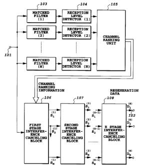
A receiver of the system comprises, as shown in
Fig. 4, matched filters 103 and received level
detectors 104 provided corresponding to channels 1-
N, a channel ranking unit 105, and interference
canceling blocks 106-108 of first-H'th stages. The
matched filter 103, in each path of each channel,
performs correlation detection of the spreading code
replica with the reception signal using the
spreading code in phase with the reception timing as
a spreading code replica. The received level
- 36 -
219'342
detector 104 makes a sum of reception power of
individual paths outputted from the matched filters
103 to detect the received level of a desired wave.
The channel ranking unit 105 outputs a channel
ranking information for controlling the order of
demodulation of users of the receiver input
according to the reception signal level of each
user. The interference canceling blocks 106-108
perform demodulation in the order of higher received
level according to the channel ranking information,
and output new interference signal replicas of
individual users using interference signal replicas
estimated by the interference canceling block of the
previous stage.
Figs. 5A and 5B individually show the
constructions of the interference canceling blocks
106 and 107.
A received spread signal S supplied to an input
end 201 of the interference canceling block 106 is
fed to delay units 202, 203 (203-2 - 203-M) and an
interference canceling unit 210-1(hereinafter
referred to as ICU). Output of the delay unit 202
is fed to the interference canceling block 107 of
the second stage. Further, output of each delay
unit 203 is fed to each interference subtractor 204
(204-2 -204-M). These delay units 203 are for
- 37 -
~1973~~
synchronizing processing timing. An interference
subtractor 204-k of the k'th user (k = 2, ..., or M)
subtracts interference signal replicas in the
corresponding interference canceling block of the
first, 2nd, ... (k-1)'th users and interference
signal replicas in the interference canceling block
of the previous stage of (k-1)'th ..., (M-1), M'th
users from the input signal.
The ICU are provided in the number of users x
number of stages. The structure is illustrated
using the ICU 210-1 of user 1 of the first stage as
an example. The ICU 210-1 comprises a matched
filter 211, a pilot symbol channel variation
estimator (herein after referred to as PCHE) 212 and
a channel variation compensator 213, a RAKE combiner
214, and a data decision block 215 provided in each
of multiple paths, a channel variation adding unit
216 and a respreader 217 provided in each path, and
an adder 218, and output of the adder 218 (channel
variation estimation value) is outputted from an
output terminal 219.
The matched filter 211 makes cross-correlation
of a received spread signal with a spreading code
for each path, and outputs a despread signal. The
PCHE 212 estimates a variation in the transmission
path of each path of each symbol in the despread
- 38 -
CA 02197342 2001-08-08
signal. That is, for each path, the transmission
variation estimated by the pilot symbol is
interpolated into the information position in the
section to estimate the transmission path variation
in each information symbol. The channel variation
compensator 213 compensates an estimated phase
variation for each path. The RAKE combiner 214
makes weighted combination of output signal of each
channel variation compensator 213 according to the
magnitude of reception power of each path. The data
decision block 215 decides output signal of the RAKE
combiner and outputs a decision data. The channel
variation adder gives a phase variation outputted
from PCHE 212 to the signal of each path outputted
from the data decision block 215. The respreader
217 respreads the signal of each path outputted from
the channel variation adding unit 216 with a
spreading code in phase with the reception timing of
each path. The adder 218 calculates the sum of the
estimated reception signal of each path of this user
to produce a reception signal replica S1~1~ of the
user. Since the reception signal replica S1~1~ is an
interference to other channels, it can be referred
to as an interference signal replica. The
interference signal replica S1~1~ is fed to the delay
unit 204-2 of user 2, and subtracted from the
- 39 -
CA 02197342 2001-08-08
received spread signal S delayed by the delay unit
203-2. Therefore, in the ICU 210-2 of the second
user, interference canceling is made on an
interference-reduced signal. Other ICUs 210 of this
stage have the similar construction. Further, other
interference canceling blocks 107 and 108 are also
similar in construction.
Operation of the present embodiment will be
described. The matched filter 103 despreadsthe
receiver input signal using the corresponding
spreading code of each path of each user as a
replica. The received level detector 104 determines
a reception signal power for each user by adding the
matched filter correlation output value of multiple
paths to be synthesized for each user. The channel
ranking unit 105 makes ranking in the order of
higher reception signal power level and outputs
channel ranking information.
The serial canceling blocks 106 - 108 carry out
demodulation successively from the user of higher
ranking. Operation of the interference canceling
block 106 of the first stage is as follows.
The ICU 210-1 produces the interference signal
replica S1~1> of user 1. First, the matched filter
211 despreads the received spread signal S for each
path. The PCHE 212 interpolates a reception phase
- 40 -
219'~3!~~
in the pilot symbol for each information bit between
pilot symbols shown in Fig. 6, to determine a
transmission path phase variation of each
information symbol.
Fig. 7 shows a transmission path variation
estimation method of information symbol by
interpolation of pilot symbols. The axis of
abscissas of Fig. 7 indicates magnitudes of in-phase
components of pilot symbol and information symbol,
and the axis of ordinates indicates magnitudes of
these quadrature components. Pi and Pi+1 indicate
reception phase vectors of the pilot symbol
determined by averaging in each pilot symbol
section. A broken line L1 is a straight line
obtained by linear interpolation of the reception
phase vectors Pi and Pi+1 in the information symbol
section. Vectors S1, S2, ... indicate reception
phase vectors of each information symbol estimated
by the interpolation. A curve C1 indicates a locus
of actual reception phase vectors of each symbol in
association with the transmission path variation.
As shown in Fig. 7, the reception phase vector of
the information symbol can be estimated by linear
interpolation of reception phase vectors in each
pilot symbol section to the position of each
information symbol in the section. In the present
- 41 -
219' 3 ~~
embodiment, such estimation of phase variation by
pilot symbol is performed for each path of each user
of each stage. The insertion interval of the pilot
symbols is determined to follow the phase variation
of the transmission path.
The channel variation compensator 213 makes
phase compensation of the information symbol using
the resulting channel phase variation estimation
value. The RAKE combiner 214 RAKE synthesizes
phase-compensated signals of each path using the
reception power of each path as weighting. The data
decision block 215 identifies and decides the RAKE
synthesized signal to produce a reproduction data
replica. The channel variation adding unit 216 adds
an estimated phase variation of each path to the
decided data. The respreader 217 respreads the
output of the channel variation adding unit 216
using a spreading code in phase with the reception
timing of each path to obtain a interference signal
replica of each path. The adder 218 determines the
sum of interference signal replicas of individual
paths to obtain the interference signal replica S1(1)
of user 1.
Next, processing on user 2 will be described.
The interference subtractor 204-2 subtracts the
interference signal replica S1~1> of user 1 from the
- 42 -
CA 02197342 2001-08-08
received spread signal S. The ICU 210-2 estimates
an interference amount S2(1) of user 2 the same as in ICU
210-1. In this case, the input signal to the ICU 210-2 of
user 2 is improved in SIR (Signal-to-Interference
ratio) as compared with the received spread signal
S. This is because the interference signal replica
S1(1) is subtracted from the reception signal S.
Similarly, since the input signal to the ICU of a
k'th user is subtracted by interference signal
replicas of first to (k-1)'th users, the SIR can be
successively enhanced. Thereafter, on each user to
M'th user, data demodulation is performed on the
signal subtracted by the sum of interference signal
replicas up to the immediately previous user.
The second stage interference canceling block
107 carries out demodulation successively from user
1 as in the first stage interference canceling block
106. Specifically, the ICU 230-1 of user 1
determines the interference signal replica of user 1
on the signal subtracted by the sum of interference
signal replicas of other users in the first stage,
S2 (1) + S3 (1) + . . . SM(1) from a reception signal Sd,
of which delayed processing is considered, as in the
ICU 210-1.
The ICU 230-2 of user 2 of the second stage also
makes the same processing on the signal subtracted
- 43 -
CA 02197342 2001-08-08
by the sum of the first user interference signal
replica obtained in the second stage and the
interference signal replicas from the third user to
M'th user, S1~2~ + 53~1> + ...+ SM~1~, from the
reception signal Sd to determine the interference
replica of the 2nd user. Further, the ICU 230-M of
M'th user also makes the same processing on the
signal subtracted by the sum of interference signal
replicas of other users estimated in the second
stage, S1 ~2> + S2 ~2~ + . . . + SM-1 ~2~ , from the
reception signal Sd to determine the interference
signal replica of M'th user.
In other words, k'th user uses the interference
signal replica in the corresponding stage on a user
of higr:er ranking (higher in reception signal level)
than his/her own, and on the users of lower ranking than
his/her own, uses the interference signal replicas produced
in the interference canceling block of the previous
stage to calculate the interference signal replica.
The point of the present embodiment differing
from the prior art is that phase estimation of each
path is made for each user of each stage. By this
method, the accuracy of the interference signal
replica of each user is improved every time one
stage of the interference canceling block is passed.
As a result, estimation error subtracted by
- 44 -
CA 02197342 2001-08-08
interference signal replicas of other users from the
reception signal is reduced, and estimation accuracy
of phase variation is also improved.
In the present embodiment, the matched filter is
used as despreading means, however, alternatively,
sliding correlators of the number of paths can be
used to obtain the same characteristics.
Fig. 8 is a graph showing an average bit error
ratio in CDMA demodulating apparatus of the present
invention compared with the prior art apparatus. In
this graph, the axis of abscissas indicates Eb/No
(energy per bit to~noise spectral density), and the
axis of ordinates indicates the average bit error
ratio. In the prior art apparatus, that the pilot symbol
obtained by despreading is interpolated in the information
symbol section to estimate the channel variation.
is the same as in the presnet invention,
as shown in Fig ~. However, whereas in the present
~.nvention, channel estimation on each path of each
user is successively carried out for each stage of
the interference canceling block, the prior art
apparatus differs in that it uses the reception
vectors obtained in each pilot symbol section of
each user commonly for all stages of the
interference canceling block.
- 45 -
CA 02197342 2001-08-08
As can be seen from the graph shown in Fig. 8,
the improvement in the error ratio is almost the
highest when the interference canceling block is
three stages, but almost no increase in effect is
noted even if the number of stages is further
increased. Further, where Eb/No is 10 dB, the
apparatus of the present invention can reduce the
error ratio nearly one figure compared with the
prior art apparatus.
Fig. 9 is a graph comparing the average bit
error ratio with a weighted average between the
present pilot section and the previous pilot section
to make phase estimation of the pilot symbol. In the
figure, OC indicates weighting and black
circles indicate the error ratio of the present
invention. As can be seen from the figure, for
Eb/No in the vicinity of 10 dB, the error ratio of
the present invention is about 1/6 the weighted
averaging.
EMBODIMENT 2
Fig. 10 is a block diagram showing a second
embodiment of the interference canceling block of
the CDMA demodulating apparatus according to the
present invention. A difference of this embodiment
from the first embodiment is that processing of all
- 46 -
CA 02197342 2001-08-08
stages for M users is performed by a single ICU.
That is, the hardware is simplified by repeatedly
using a single ICU in time division.
In Fig. 10, the received spread signal S
5 inputted to an input terminal 301 is fed to a memory
303. The memory 303 functions as a delay unit under
control of a user control signal (channel ranking
signal) supplied from the channel ranking unit 105
of Fig. 4. That is, it corresponds to the delay
10 units 202, 203 and 223 in Figs. 5A and 5B. Further,
an interference subtractor 304 corresponds to the
interference subtractor 204 and 224, which subtracts
the interference signal replica read from an
interference signal replica. memory 305 from the
15 spread signal S read from the memory 303. The ICU
310 corresponds to the ICU 210 of Fig. 5A and the
ICU 230 of Fig. 5B, which performs channel
estimation, RAKE combining, and interference signal
replica production on the output of the interference
20 subtractor 304 to output a new interference signal
replica. Thus, the ICU 310 successively updates the
interference signal replica of each path of each
user, and writes the resulting interference signal
replica into the interference signal replica memory
25 305.
2obt o76a. t - 4 7 -
219'x'3 ~2
EMBODIMENT 3
Fig. 11 is a block diagram showing the
construction of a matched filter in ICU, a PCHE
(pilot symbol channel variation estimator) and a
channel variation compensator in a third embodiment
of the CDMA demodulating apparatus of the present
invention. The principle will be described before
describing the third embodiment in detail.
In a cellular communication system, in a
downward channel from a base station to a mobile
station, transmission timing of each user is
synchronized with each other. However, since
transmission delay differs in an upward channel
responding to it, information symbol timing and
spreading code chip timing are asynchronous.
Fig. 12 shows a frame-arrangement of each user
in an asynchronous channel. As shown in the figure,
on the pilot symbol of user X, there is an
interference of the information symbol in the
previous pilot block of user Y. This is because in
the mufti-stage interference canceler, an estimation
interference replica is produced in a unit of chip.
Therefore, mufti-stage interference canceling
performed in a unit of 1 pilot block is required to
be performed in a unit of time including information
symbols before and after the pilot block. That is,
- 48 -
2~~~34z
it is necessary to produce an estimation
interference replica in a unit of interference
canceling time TA including the information symbols
before and after, rather than pilot block time TB as
shown in Fig. 12. Therefore, processing such as
channel ranking by an average value of reception
signal level, production of estimated interference
replica, and the like must be performed in every
processing time TA.
Fig. 13 is a vector diagram showing the
principle of channel estimation for the production
of interference replica in an asynchronous channel.
A difference between the processing in Figs. 7 and
13 is that the channel variation is estimated by
extrapolating a reception envelope line of the pilot
symbol for several symbols outside a pilot symbol
Pi. Since the number of the outside symbols is
several symbols even considering transmission delay,
no substantial error is produced even if the channel
variation estimation value of the pilot symbol is
adopted as a channel estimation value of the
information symbol outside the pilot symbol. By
using these estimation values, the spread signal
replica of the information symbol outside the pilot
symbol can be produced. Further, for an information
symbol sandwiched between two pilot symbols,
- 49 -
m9~~~z
variation is estimated by interpolating the pilot
symbols in the information symbol section, as in
Fig. 7, to produce the spread signal replica of the
information symbol. By subtracting these spread
signal replicas from the reception signal S to form
the multi-user interference canceler even in an
upward asynchronous channel. With this method, if
only the reception signal in 1 pilot block time TB
is stored in the memory, interference replicas can
be produced in the range of longer processing time
TA, thereby achieving an efficient multi-user
interference canceler.
Reverting back to Fig. 11, the construction of
the PCHE and channel variation compensator in the
ICU of the present embodiment will be described.
Other construction is the same as in Fig. 5A.
In Fig. 11, the received spread signal applied
to an input terminal 201 is written in a reception
signal memory 403. The memory 403 stores the
reception signal in 1 pilot block time TB in Fig.
12. The stored reception signal is fed and despread
in a matched filter 411. The despread signal is fed
to a delay unit 413, a channel estimator 415, and a
pilot frame synchronizer 419.
The channel estimator 415 extracts a pilot
symbol of known pattern from the despread signal,
- 50 -
CA 02197342 2001-08-08
which is compared with the pilot symbol supplied
from a pilot signal generator 417 to estimate the
phase variation. In this case, the pilot symbol
generation phase of the pilot signal generator 417
is controlled by a signal from the pilot frame
synchronizer 419.
The phase variation estimated by the channel
estimator 415 is converted to a signal and fed to an
interpolator 421 and an extrapolator 423. For an
information symbol inside the pilot block, the
estimation values estimated in the pilot section of
both sides are interpolated into the position of each
information symbol to estimate channel variation of each
information symbol. On the other hand, for an
information symbol outside the pilot block, the
estimation channel variation in the pilot section
closest to the information symbol is determined as a
channel variation estimation value. As described
above, the number of information symbols, even
considering transmission delay in a cellular system
with a cell radius of several km, is only a few.
These channel variation estimation values are fed to
a fading distortion compensator 425, and multiplied to
the despread signal passed through the delay unit
413 to compensate for the channel variation.
- 51 -
CA 02197342 2001-08-08
The processing is performed on each path of this
user, and the channel variation compensated despread
signal of each path is fed to a RAKE combiner 430.
The RAKE synthesized signal is decided by a data
decision block 440.
With the present embodiment, even in an upward
asynchronous channel, multi-stage interference
canceling is possible by block processing in a unit
of constant time. In the present embodiment, since
it is not necessary to communicate interference
replica information between blocks, the apparatus
can be simplified.
EMBODIMENT 4
Fig. 14 is a block diagram showing the ICU of
the interference canceler after the second stage of
a fourth embodiment of the CDMA demodulating
apparatus according to the present invention. The
present invention eliminates interference replicas
due to multipath signals of own channel.
In a mobile communication environment, multipath
transmission paths are formed due to reflection from
buildings and the ground. The multipath signal of own
channel, as in the signals from other users, also
produces cross-correlation at despreading causing
interference. As in the above-described
- 52 -
~1.9'~~~~
embodiments, in an arrangement where channel
estimation is successively performed for each stage
using pilot symbols, the input signals of ICU of the
stages after the second stage include interference
replicas due to multipath signals of own channel.
In a wideband DS-CDMA of high-speed chip rate,
due to its low time resolution, the reception signal
can be separated to a number of multipath signals,
and a RAKE combining function is effective.
However, in the RAKE combining, the signal power per
1 path of multipath is reduced, interference from
multipath signals of own channel becomes not
negligible. Therefore, in the multi-stage
interference canceler, it is necessary to use the
signal subtracted not only by interference replicas
of other users but also by interference replicas due
to multipath signals of own channel as an ICU input
signal to improve SIR even further.
Fig. 14 shows the ICU of loth user of i~th stage
(i being an integer of 2 or more) of the CDMA
demodulating apparatus which is achieved under such
a concept.
Differences of ICU 510-k from the ICU 210 in the
first embodiment shown in Fig. 5A are as follows.
(1) Interference replica eliminators 505 (505-1
-505-Lk) are newly provided. The interference
- 53 -
219'~3~~
replica eliminators 505 are to eliminate
interference replicas due to multipath waves of own
channel.
An interference subtractor 504-k of Fig. 14
corresponds to the interference subtractor 224 of
Fig. 5B, which subtracts interference replicas of
other users from received spread signal S2 (delayed
received spread signal S) supplied to an input
terminal 501. That is, the interference subtractor
504-k, for users from the first user to (k-1)'th
users before itself, subtracts the interference
replicas obtained in the present stage i from the
received spread signal, and for users from (k+1)'th
to M'th user after itself , subtracts the
interference replicas obtained in the immediately
prior (i-1)'th from the received spread signal. A
received spread signal S3 subtracted by interference
replicas of other users is fed to the interference
replica eliminators 505.
The interference replica eliminators 505
eliminate by subtracting interference replicas of
other multipath obtained in the immediately prior
(i-1)'th stage from the received spread signal S3.
For example, the interference replica eliminator
505-1 subtracts all multipath interference replicas
after the second multipath obtained in the previous
- 54 -
~~.9'~~~Z
(i-1)'th stage from the received spread signal S3.
In general, considering Li'th multipath wave of k'th
user, interference replicas other than Li of k'th
user estimated by the previous stage ICU are
subtracted from the received spread signal S3. The
thus obtained received spread signal is fed to the
matched filter 211 provided corresponding to each
path, and thereafter subjected to the same
processing as in the first embodiment, and respread
by the respreader 217. In Fig. 14, Lk is the number
of RAKE combining paths of user k.
(2) Output of the respreader 217 of each path is
outputted from the output terminal 507 (507-1 - 507-
Lk) as an interference replica of multipath wave of
the present stage. These interference replicas are
fed to the next (i+1)'th stage to be used for
eliminating interference replicas of multipath
waves.
In the ICU of Fig. 14, the interference replica
eliminators 504 and 505 are disposed outside and
inside the ICU, but the present invention is not
limited to this configuration. In short, a signal
subtracted by interference replicas of other users
and interference replicas of multipath waves of
other paths of own channel may be subtracted from
- 55 -
CA 02197342 2001-08-08
the received spread signal as an input signal to the
matched filter 211 in the ICU 510.
With the present embodiment, SIR can be improved
even further as compared with the first embodiment.
As a result, reception characteristics can be
improved thereby increasing the subscriber capacity
of the system.
EMBODIMENT 5
Fig. 15 is a block diagram showing the
construction of an interference canceler after the
second stage of a fifth embodiment of the CDMA
demodulation apparatus according to the present
invention. In the present embodiment, the decision
data outputted from a data decision block 215 is
matched in amplitude with that of a desired wave to
produce an interference replica of each multipath of
each user in high accuracy.
A difference of the fifth embodiment shown in
Fig. 15 from the fourth embodiment shown in Fig. 14
is that a circuit for determining an amplitude value
of decision data is newly provided. This point will
be described below. A reception signal power
detector 521 (521-1 - 521-Lk: Lk being the number of
RAKE combining paths) determines a signal power of
despread signal of each path. This can be
- 56 -
21973~~
determined as a square-law sum of amplitude of the
in-phase component and quadrature component of the
despread signal. An adder 523 adds each output of
the power detector 521 of the RAKE combining
multipaths to obtain a reception signal power after
RAKE combining. An in-phase/quadrature component
amplitude converter 525 determines absolute
amplitude S of in-phase component and quadrature
component of the reception signal from the reception
signal power. Since the amplitude values of
individual symbols are varied by the influence of
noise, the values are averaged over 1 pilot block to
obtain an amplitude value removed of the influence
of noise. The averaging is achieved by an averaging
unit 527. The averaged amplitude value is fed to a
multiplier 529, to be adjusted so that the amplitude
value of the decision data matches with the
amplitude value of the reception signal.
With the present embodiment, interference
replicas of each multipath of each user can be
produced with good accuracy.
EMBODIMENT 6
Figs. 16A and 16B are block diagrams showing the
construction of a first stage interference canceling
block of a sixth embodiment of th CDMA demodulating
- 57 -
219'~~42
apparatus according to the present invention. Other
components are similar to the construction shown in
Fig. 4. That is, the matched filter 103, the
received level detector 104, the channel ranking
unit 105, the interference canceling blocks 107 and
108 after the second stage are similar to those in
the first embodiment.
As described above, the matched filter 103 makes
correlation detection of the spreading code replica
synchronized with the received spread signal of each
path of each channel with the received spread signal
S. The received level detector 104 calculates the
sum of reception power of each path outputted from
the matched filter 103 to detect the reception
signal level of a desired wave. The channel ranking
unit 105 outputs channel ranking information for
controlling the order of demodulation of users of
receiver input.
A difference of the interference canceling block
of the present embodiment from the interference
canceling block shown in Fig. 5A is that the
interference canceling block of first - loth users
is constructed about a decorrelator (decorrelation
filter) as the center.
In Figs. 16A and 16B, matched filters 601 (601-1
- 601-k) despread signals of each path of k users
- 58 -
219'342
from higher reception signal level according to the
channel ranking information supplied from the
channel ranking unit 105. A decorrelator 603
functions as a decorrelation filter, which outputs
despread spectrum interference eliminated from each
other using signals from each matched filter of each
path of k users from higher reception signal level
as an input spectrum according to the information
from the matched filter 601 and the channel ranking
unit 105.
Coherent detector/interference production units
610 (610-1 - 610-k) has the same construction as the
ICU 210 of Fig. 5A with the matched filter 211
removed, which calculates interference replicas of
the first - k'th channels from the output signal of
the decorrelator 603.
For (k+1)'th - M'th users, the procedure is
similar to the corresponding portion of the first
embodiment. That is, the delay unit 203, the
interference subtractor 204, and the ICU 210 are
similar to those in the first embodiment. Thus, for
k users of high reception signal level, interference
replicas are estimated according to the output of
the decorrelator 603, and using the estimated
interference replicas, demodulation is performed on
remaining (M-k) users. Further, in the interference
- 59 -
~19'~J~~
canceling block after the second stage, estimated
interference replicas of each user are calculated as
in the first embodiment. The interference canceling
block 108 of the last (H'th) stage outputs the
reproduction data of each user.
The decorrelator 603 makes quadrature processing
on ~Lk users of high reception signal level to
improve the SIR of the received spread signal.
Quadrature processing by the decorrelator 603 is
performed as follows. Specifically, the
decorrelator 603 produces the received spreading
code replicas of each path from the spreading code
of k users and the reception timing. Then, cross-
correlation between ~Lk spreading codes is
calculated to produce a correlation matrix using the
cross-correlation values. Further, an inverse
matrix of this correlation matrix is calculated and
applied to reception signal vectors to make
quadrature processing between reception signal
vectors of all paths of k users.
As a result, for example, signals of each path
of the first user quadrate with signals of each path
of 2nd - k'th users. Therefore, interference
signals to each path of the first user are only
residual interference signals from each path of
(k+1) to M'th users, thus the SIR is improved. On
- 60 -
CA 02197342 2001-08-08
each path of k users which is quadrature processed
by the decorrelator 603 is subjected to channel
variation estimation, channel variation
compensation, RAKE combining, and interference
replica production by the coherent
detector/interference production unit 610. These
interference replicas of k users are input to the
ICU 210 - (k+1) of (k+1)'th user, which are
processed as in the first embodiment.
V~lith the present embodiment, defect of the first
embodiment is eliminated. That is, in the first
embodiment, the user of high reception signal level
which is subjected to interference replica
estimation in the first step has been
disadvantageous. However, in the present
embodiment, since, for the first k users,
interference canceling is performed by the
decorrelator 603, such a defect of the first
embodiment can be eliminated. The value of k is
typically 2 or more, and less than the spreading
factor PG, but cannot be an excessively high value.
This is because the dimension of the matrix treated
by the decorrelator rapidly increases as the number
of channels increases.
- 61 -
~197~~~~
EMBODIMENT 7
Figs. 17A and 17B are block diagrams showing a
seventh embodiment of an interference canceling
block of the CDMA demodulating apparatus according
to the present invention. A difference of the
present embodiment from the sixth embodiment is that
processing of all stages to M users is carried out
by a single ICU. That is, the hardware is
simplified by repeatedly using a single ICU in time
division.
Since the construction and functions of the
present embodiment can be easily understood from the
second and sixth embodiments, detailed description
thereof is omitted.
EMBODIMENT 8
Figs. 18A and 18B are block diagrams showing an
eighth embodiment of the CDMA demodulating apparatus
according to the present invention.
The present embodiment is a simplification of
the first embodiment shown in Fig. 4 and differs
from the first embodiment in the following points.
(1) Construction of interference canceling
blocks 700, 720 and 740 is simplified over the
- 62 -
~19"~~ ~~
construction of the interference canceling blocks
106, 107 and 108 shown in Fig. 4.
Figs. 19A and 19B are block diagrams showing the
construction of first and second stage interference
canceling blocks. However, the portion surrounded
by the broken line in Fig. 19B relates to a
modification of the present embodiment and will be
described later.
The interference canceling blocks shown in Figs.
19A and 19B differ from the interference canceling
blocks shown in Fig. 5A in the construction of the
ICU 710 (710-1 - 710-M). The ICU 710 does not
perform estimation/compensation and data decision of
the despread signal. Specifically, the components
212-216 are omitted from the ICU 210 of Fig. 5A.
That is, the matched filter 211 of the ICU 710
despreads the received spread signal in each path
and outputs the despread signal. The despread
signal is fed directly to the respreader 217. The
respreader 217 respreads the despread signal of each
path using the spreading code replica synchronized
with the received spreading code of each path to
obtain the interference signal replica of each path.
The adder 218 determines the sum of interference
signal replicas of each path. This is the estimated
interference replica S1~1~ of user 1. Thus, the
- 63 -
signal despread by the matched filter 211 is
immediately respread by the respreader 217 to
simplify the circuitry compared with the first
embodiment.
(2) The pilot interpolation/RAKE combining
coherent detectors 750, 760 and 770 are connected to
the output side of the interference canceling block
740 of the last stage.
Interference-reduced signals D1~H~, D2~H~, ...,
DM~H~ are outputted from ICU of each channel of the
interference canceling block 740 of the last stage,
that is, H~th stage. These signals are inputted
individually to the pilot interpolation/RAKE
combining coherent detectors 750, 760 and 770
provided in each channel. Construction and
operation of the detector 750 is the same as the
construction and operation from the matched filter
211 to the data decision block 215 in ICU 210 of the
first embodiment, which will be briefly described
below.
The matched filter 751 receiving the signal D1(H)
from the interference canceling block 740 despreads
the signal in each path. The PCHE (pilot symbol
channel variation estimator) 752 estimates variation
of each pilot symbol, which is averaged in the pilot
section to be determined as a phase variation
- 64 -
219'~3~~
estimation value. The channel variation compensator
753 interpolates the phase variation estimation
value into each position of information symbol
sandwiched between pilot symbols to estimate the
channel phase variation of each information symbol,
and compensates for channel variation of information
symbol section using the estimation channel phase
variation to the output of the matched filter 751.
The RAKE combiner 754 makes RAKE combination of the
phase-compensated signal of each path using the
reception power of each path as weighting. The data
decision block 755 decides the RAKE synthesized
signal to output reproduction data. Thus, absolute
synchronization detection is achieved.
The present embodiment, unlike the above-
described other embodiments, does not perform phase
estimation of each path for each user of each stage.
This considerably simplifies the construction of the
interference canceling block of each stage. Since
the interference signal replica in the present
embodiment is not subjected to data decision, it is
subject directly to the influence of thermal noise,
however, this is nearly equivalent to the influence
of decision error when the producing the
reproduction data replica in the above-described
- 65 -
219~~~12
other embodiments. Further, since the reproduction
data replica is not produced, it is considered that
in the resulting interference signal replica,
influence of cross-correlation of each spreading
code is transmitted to the interference canceling
block of each stage, but the influence can be
reduced by suppressing the number of stages of the
interference canceling blocks to a few stages.
In the present embodiment, the matched filter is
used as despreading means, however, alternatively, a
serial canceler of the same characteristics can be
constructed using a sliding correlator.
The portion surrounded by the broken line in
Fig. 19B indicates a modification of the eighth
embodiment. In this modification example, input
signal to each ICU 730 of the interference canceling
block 720 of the second stage is inputted to the
pilot interpolation/R.AKE combining coherent detector
750.
EMBODIMENT 9
Fig. 20 is a block diagram showing a ninth
embodiment of the CDMA demodulating apparatus
according to the present invention. The present
embodiment is a simplified example of the second
embodiment shown in Fig. 10, and since construction
- 66 -
X19 ~~4?
and functions thereof are understood from the second
and eighth embodiments, detailed description thereof
is omitted.
EMBODIMENT 10
As described above, in DS-CDMA, each
communicator is subject to instantaneous variation
due to fading, short period variation, and distance
variation. Therefore, to satisfy the desired
reception quality in a mobile station, it is
necessary to make a transmission power control to
control the SIR in the receiver input of the base
station.
Transmission power control is divided into an
open loop type and a closed loop type. In the
former, SIR is measured at the receiving side, and
the transmission power is controlled according to
the measured result. In the latter, SIR is measured
at the receiving side, and according to a difference
between the measured result and a target SIR value,
a transmission power control signal is transmitted
to the transmission counterpart to control the
transmission power of the counterpart. When there
is no correlation between transmission and reception
carrier levels, the closed loop type transmission
power control is effective.
- 67 -
219'~~~~
Characteristics when the closed loop type
transmission power control is applied in CDMA mobile
communications are determined mainly by control
delay.
Fig. 21 is a graph showing an example of error
characteristics of transmission power control when
transmission power control delay is used as a
parameter. As the fading rate fdT (abscissas)
normalized by the control period of transmission
power control increases, control error (ordinates)
of transmission power increases. When fading
exceeds a certain rate, transmission power control
does not follow the fading, and the characteristic
becomes flat. Further, as the control delay
increases, the flat portion of control error
increases. If transmission power control error
increases, communication quality degrades in the
section where SIR is lower than the target value,
which leads to a reduction in the subscriber
capacity. Therefore, it is desirable that delay of
transmission power control be as small as possible.
On the other hand, even if transmission power
control is perfect and SIR in the receiver input is
guaranteed to be constant, spreading codes will
never completely quadrate with each other under
multipath environment of mobile communications.
- 68 -
21~ ~34~
Therefore, communication is affected by interference
from other communicators, the magnitude of which is
a reciprocal of the spreading factor at an average
per one of other communicators. Therefore, when the
number of communicators in the same frequency band
increases, the interference signal power level
increases, and the communicator capacity per cell is
limited. To further increase the communicator
capacity per cell, the above-described interference
canceling technique is used.
Since, when an interference canceler is used at
the receiving side, the interference power is
reduced and the reception SIR is improved,
transmission power can be reduced compared with the
case where no interference canceler is used.
Therefore, interference amount to other
communication channel is reduced, and reception SIR
of each communication channel is improved even
further.
To efficiently utilize the SIR improvement
effect by the interference canceler, it is necessary
to measure SIR of the signal after interference
reduction. However, the multiuser interference
canceler has processing delay. For example, in the
multi-stage type, processing delay is increased with
increases in the number of stages and the number of
- 69 -
21~~3~?
users. Further, in the decorrelator type, as the
numbers of users and paths increase, processing
amount required for inverse matrix calculation
increases, further, to perform quadrature processing
to a plurality of past and future symbols, a
processing delay of several symbols is unavoidable.
As described above, characteristics of
transmission power control are determined mainly by
control delay. When SIR of the signal after
interference reduction is measured, the control
delay is considerably large. As a result,
transmission power control error becomes large,
leading to a reduction in subscriber capacity.
For the above reasons, a method in which the
reception SIR improving effect when the multiuser
interference canceler is used is applied to closed
loop transmission power control has not been
disclosed. The present embodiment, when the
interference canceler is applied in the receiving
side, causes closed loop transmission control to
efficiently function, thereby achieving transmission
power reduction and subscriber capacity increasing
effects.
Fig. 22 is a block diagram showing an embodiment
of applying the transmission power control to the
- 70 -
CA 02197342 1999-04-12
CDMA demodulating apparatus according to the present
invention.
In Fig. 22, a matched filter 801 performs
correlation detection using the spreading code
5 synchronized with the reception timing of each path
of each communication channel to N (N being an
integer of 2 or more) communicators communicating in
the same frequency band. An SIR measuring unit 802
measures SIR of the output signal of the matched
10 filter 801. A multiuser interference canceler 803
outputs an interference-eliminated signal on each
communication channel. A reception quality
measuring unit 804 measures the reception quality of
the interference-eliminated signal of each channel
15 outputted from the multiuser interference canceler
803. A target SIR setting unit 805 compares the
reception quality outputted from the reception
quality measuring unit 804 with a predetermined
reception quality to set a target SIR value. A TPC
20 (transmission power control) bit production unit 806
compares the reception SIR obtained from the SIR
measuring unit 802 with the target SIR obtained from
the target SIR setting unit 805 to produce a
transmission power control signal.
25 Figs. 23A and 23B are block diagrams showing
details of the reception quality measuring unit 804,
- 71-
~19'~~4~
Fig. 23A shows the reception quality measuring unit
804 for measuring the frame error ratio to monitor
the reception quality, and Fig. 23B shows the
reception quality measuring unit 804 for measuring
the error ratio of pilot symbol to monitor the
reception quality. While transmission power control
is directed to follow momentary variation to achieve
the target SIR, the reception quality measuring unit
804 performs averaging over a relatively long time
and monitors communication quality in the output of
the interference canceler 803 to correct the target
SIR value of transmission power control. Therefore,
processing delay of the interference canceler 803
has no problem.
In Fig. 23A, a CRC check unit 811 performs CRC
test (Cyclic Redundancy Check) of reception data
outputted from the multiuser interference canceler
803. That is, reception data is inputted to the
divider circuit by the produced polynomial to decide
whether the remainder is zero or not. If the
remainder is zero, it is decided that there was no
frame error in the communication path, and if the
remainder is not zero, it is decided frame error to
have occurred.
A frame error calculation unit 812 calculates
the number of frame errors and outputs a frame error
- 72 -
219'~3~?
ratio. A frame error ratio threshold value
generator 813 outputs a frame error ratio threshold
value. A reception quality decision block 814
compares the frame error ratio with the threshold
value to output a signal indicating the reception
quality. A target SIR setting unit 805 corrects a
reference SIR by this signal and outputs a corrected
reference SIR.
The reception quality measuring unit 804 by the
error ratio of pilot symbol, shown in Fig. 23B,
comprising the following. A pilot symbol production
unit 821 produces a pilot symbol of a known pattern.
A pilot symbol error ratio calculation unit 822
extracts the pilot symbol from reception data
outputted from the multiuser interference canceler
803, and compares it with the pilot symbol supplied
from the pilot symbol production unit 822 to
calculate the pilot symbol error ratio.
The pilot symbol error ratio threshold value
generator 823 outputs a threshold value of pilot
symbol. The reception quality decision block 824
compares the pilot symbol error ratio with its
threshold value and outputs a signal indicating the
reception quality. The target SIR setting unit 805
corrects the reference SIR by the signal and outputs
a corrected reference SIR.
- 73 -
CA 02197342 2001-08-08
Operation of the present embodiment will be
described. The matched filter 801 detects
correlation of the received spreading code with the
spreading code replica for each path of each
communication channel and outputs the despread
signal of each user. The SIR measuring unit 802
measures SIR of each user using the despread signal.
On the other hand, the multiuser interference
canceler 803 outputs the interference-eliminated
despread signal using the received spread signal.
However, the despread signal accompanies processing
delay.
The reception quality measuring unit 804
measures communication quality of the despread
signal outputted from the interference canceler 803.
The measured communication quality is fed to the
target SIR setting unit 805 to be compared with a
predetermined reception quality.
Fig. 24 is a schematic view comparing the output
of the matched filter 801 with the output of the
interference canceler 803. The target SIR is set by
the target SIR setting unit 805 as follows.
(1) The target SIR is set to a slightly lower
value than a required SIR in the output of the
- 74 -
21~'~3~~
interference canceler 803 in view of an interference
reduction effect by the interference canceler 803.
(2) Since the interference eliminating
capability of the interference canceler 803 can be
estimated to some extent from the number of
simultaneous communicators, the target SIR is also
set according to the number of simultaneous
communicators .
(3) When communication quality measured by the
reception quality measuring unit 804 is better than
the desired quality, the target SIR is lowered.
This prevents excessive quality of communication and
allows the transmission power to be reduced even
further.
(4) On the contrary, when the communication
quality measured by the reception quality measuring
unit 804 is worse than the desired quality, the
target SIR is increased.
(5) By repeating the correction of (3) and (4),
the target SIR is converged to a value at which the
desired quality is satisfied in the output of the
interference canceler 803.
- 75 -
219'~~42
The TPC bit production unit 806 compares the
measured SIR outputted from the SIR measuring unit
802 with the target SIR, and when the former exceeds
the latter, sends a control signal (TPC bit) to the
other communicator to cause the counterpart to
decrease the transmission power. On the contrary,
when the latter exceeds the former, a control signal
is sent to the other communicator to cause it to
increase the transmission power. This can achieve
closed loop transmission power control which follows
instantaneous variation of the transmission path.
Further, the required reception quality is set
for each communication channel. This is because the
required communication quality differs according to
the provided service (voice transmission, image
transmission, data transmission, and the like).
EMBODIMENT 11
Fig. 25 is a block diagram showing another
embodiment in which transmission power control is
applied to the CDMA demodulating apparatus according
to the present invention.
The present embodiments has the following
features.
- 76 -
2197~~~?
(1) The replica reproduction multistage
interference canceler of the first embodiment is
used as the multiuser interference canceler 803.
(2) A pilot symbol average error ratio measuring
unit 804 for measuring the communication quality by
the pilot symbol error ratio shown in Fig. 23B is
used as the reception quality measuring unit 804.
Since operation of the present embodiment is
understood from the description of embodiments 1 and
10 and Fig. 23B, it will be described briefly.
In each stage of the interference canceler 803,
interference signals from other communicators are
demodulated and decided to reproduce transmission
information data replicas. Interference signal
replicas of each channel are calculated from the
reproduced data replicas, and subtracted from the
reception signals to enhance SIR to the desired wave
signal to be demodulated.
On the other hand, the channel ranking unit 807
performs channel ranking to rearrange the
communicators in the order of stronger reception
power. According to the result, the interference
canceler 803 demodulates the desired wave signal in
the order of stronger reception power. By
performing this operation over individual stages,
77 _
219'~~4~
the later the stage, the more the SIR is improved.
Further, as the accuracy of interference signal
replica is improved in each stage of the
interference canceler 803, variation estimation
accuracy of each channel is improved. Therefore,
the interference canceling effect is improved when
there are a large number of communicators.
EMBODIMENT 12
Fig. 26 is a block diagram showing a yet further
embodiment in which transmission power control is
applied to the CDMA demodulating apparatus according
to the present invention. A difference of the
present embodiment from the embodiment 11 shown in
Fig. 25 is that a reception quality measuring unit
comprising a deinterleaver 808, a Viterbi decoder
809, and a frame error ratio measuring unit 810 is
provided in place of the pilot symbol average error
ratio measuring unit 804.
The same functions and effect as of embodiment
11 can also be obtained using this construction.
_ 78 _