Note: Descriptions are shown in the official language in which they were submitted.
WO 97100501 PCT/ICR96/OOO6I
219341
1
NON-CONTACTING TYPE RADIO FREQUENCY
RECOGNIZING CREDIT CARD SYSTEM
T . . OF THF: Tj~7FNTTON
The present invention relates to a credit card
system, and more specifically, to a non-contacting type
radio frequency recognizing credit card system in which
a credit card inquiry is possible in a state with a
credit card nat contacted with a card reader, and in
which the credit card inquiry time and the data
exchange time between a credit card and a card reader
are drastically reduced.
D .S .RT TTON O TH . RTOR RT
Generally, a credit card possessor can buy
commodities and services without paying cash under the
guarantee of the credit card managing company, and also
can carry out non-passbook transactions with a bank
through a cash payment apparatus.
The size of the credit card has been determined
as 3.375 inches length, 2.125 inches width and 0.03
inches thickness internationally sc that they can be used
worldwidely through subscribed stores. The data for
judging on the authenticity of the credit card holder
are stored in the magnetic strip of the credit card and
in the card managing company. Upon verifying the data,
the subscribed store approves the transaction.
FIGS. 1A and 1B illustrate the basic external
appearance of a credit card.
As shown in these drawings, a credit card 10
has a frontal face 20 on which there are shown a card
number 21 consisting of 16 Arabian numerals, a name 22
of
the card owner, an expiry date 23 of the card, a name 24
of the card issuing company, a logo 25 of the card
issuing company, letters "local" or "international" 26,
WO 97!00501 PCT°fKR96/00061
211347
2
and a hologram 27 as the means for preventing illegal
copying of the credit card.
Tn the rear face 30 of credit card, there are
shown a magnetic strip 32 which stores the identification
of the card ownerr the paying passbook account number,
and the validity of the credit card.
In case where a commodity ar a service is to be
paid by using such a credit card, the credit card is
inserted fnto a card reader, so that the magnetic strip
of the credit card would pass contactingly through the
card reader. The credit card number thus read by the card
reader is transmitted from the card reader through an
electric tine (telephone line) to the credit card managing
company. The credit card managing company checks on the
payment limit and on the existence or absence of
dishonored transactions, and it transmits. an approval
number or a disapproval number to the card inquiry
terminal.
However, the above described conventional card
inquiry system takes too much time (several seconds or
several scores of seconds) in completing the card inquiry.
Such a time consumption in the conventional system has
been a serious impediment in broadening the area of the
credit card utilization.
Another problem in the conventional system is
that credit cards are apt to be damaged and thus the
reading errors in the card reader are very frequent.
In the conventional system, the card reader
reads the data of the magnetic strip by contacting with
the magnetic strip, whfch may shorten the life of a credit
card. When a credit card passes through a card reader,
if the passing speed is too fast or too slow, then
reading errors are occurred, and if the such an errors are
repeated, the magnetic strip would be worn out and
consequently the life of a credit card would be shortened.
WO 97/00501 PCTlKR96100061
3 219347
$ 1MMAR TH . Tr~'[TF'NTTf1 t
The present invention is intended to overcome
the above described disadvantages of the conventional
system, and therefore, an object of the present
invention is to provide a non-contacting type radio
frequency recognizing card (hereinafter "RF card")
system, so that the card reader may read the
information in the card in a non-contacting manner. In
the present invention, the information can be exchanged
between a credit card and a card reader without being
contacted with each other.
Another object of the present invention is to
reduce the card-reading time drastically, so that a
credit card may be used to pay traffic fares or the like
which requires the card-reading time to be extremely
short.
It is still another object of the present
invention to provide a no-battery type RF credit card. In
the present invention, the card information can be
exchanged between the card and a card reader without
battery in the card.
It is still another object of the present
invention to provide a RF credit card comprising advanced
payment function, in which a part of the IC memory of the
RF credit card is designated as an area for storing a
certain amount of money so as to incorporate an advance
payment function, thereby making it possible to carry out
off-line services.
It is still another object of the present
invention to provide an RF credit card system in which a
part of the IC memory of the credit card is designated as
ar_ area far debit card system, thereby providing an
instant payment function.
In achieving the above objects, the non-
CA 02197347 1999-O1-04
4
contacting type radio frequency recognizing credit card
system according to one aspect of the present invention
includes:
- a batteryless type RF card having an antenna
coil wound around the inner edges of said RF card within
said card several times and an IC disposed within said
antenna coil, and being energized by received radio wave
from a card terminal so as to transmit its own card number
to said card terminal by a radio frequency;
- said card terminal radiating a radio wave to
generate an indused electromotive force in said RF card,
receiving said card number data by RF, and transmitting the
card number data, received through a radio frequency, to a
wire-connected terminal computer for an inquiry to a black
lists and
- said terminal computer reading the card number
data from said card terminal to make an inquiry to a black
list which is updated from the central computer
periodically or intermittently, to make a decision for
issuing an approval of a transaction or a disapproval of
the transaction, and to transmit the result of the decision
to said card terminal.
According to another aspect of the present
invention there is provided a non-contacting type radio
frequency recognizing credit card system including:
- a batteryless type RF card having an antenna
coil wound around the inner edges of said RF card within
said card several times and an IC disposed within said
antenna coil, and being energized by received radio wave
from a card terminal so as to transmit its own card number
to said card terminal by a radio frequency;
CA 02197347 1999-O1-04
4a
- said card terminal radiating a radio wave to
generate an indused electromotive force in said RF card,
and receiving said card number data by RF, and having a
black list data storage module which updated black list
from the central computer through the terminal computer
periodically or intermittently, to make a decision for
issuing an approval of a transaction or a disapproval of
the transaction; and
- a terminal computer for receiving and
summarizing the details of transaction data transmitted
from said card terminal to transmit the summarized data to
the central computer, and for receiving updated black list
data from said central computer to transmit them to said
card terminal.
BRIEF DESCRIPTION OF THE DRAWINGS
The above objects and other advantages of the
present invention will become more apparent by describing
in detail the preferred embodiment of the present invention
with refrence to the attached drawings in which:
FIGs. 1A and 1B illustrate the frontal face and
the rear face of the usual credit card;
FIG. 2 is a block diagram showing the constitution
of the non-contacting type radio frequency recognizing
credit card system according to the present invention;
FIG. 3 illustrates the internal structure of the
non-contacting type radio frequency recognizing credit card
(RF card) according to the present invention;
CA 02197347 1999-O1-04
4b
FIG. 4 illustrates the internal structure of
another embodiment of the RF card according to the present
invention;
WO 97/00501 PCTIHI296100061
219»4~
FIG. 5 is a block diagram showing the internal
structure of the RF card according to the present
invention;
FIG. 6 is a block diagram showing the
5 constitution of the card terminal according to the
present invention; and
FIG. 7 illustrates the constitution of a subway
fare collecting system as an example of the application of
the present invention.
i0
DF~CRIPTTaN OF TH . R .FFRF .n FMgpDTM NT
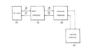
FIG. 2 is a schematic view showing the
constitution of the system of the present invention. As
shown in this drawing, the system of the present
invention includes an RF card 40, a card terminal 70 and
a terminal computer 80.
The card terminal 70 radiates a radio frequency
through an antenna continuously or periodically to supply
power to the RF card 40. Further the card terminal 70
reads a card number from the RF card 40, and transmits
the received data to the terminal computer 80. And,
conversely, the card terminal 70 receives data from the
terminal computer 80, and transmits the data received
from the terminal computer 80 to the RF card 40.
The terminal computer 80 receives card number
data from the card terminal 70, and makes an inquiry
for the data to a blac:.c list so as to make an immediate
decision on an approval or disapproval of a transaction.
The terminal computer 80, in the meantime, transmits the
RF card transaction details to a central computer 90
periodically, and receives an updated black list from the
central computer 90 to store it in itself.
As the terminal computer 80, a personal
computer will be sufficient in most cases.
FIG. 3 illustrates the internal structure of the
WO 97JOOS01 PCTlKR96100061
219737
6
RF card according to the present invention. As shown in
this drawing, between a frontal face 20 and a magnetic
strip 32, i.e., within the RF card 40, there is
disposed an antenna coil 60 which consists of many turns
of a thin wire concentrically coiled. There is further
disposed an integrated circuit 50 which is connected to
the antenna coil 60.
The antenna coil 60 and the integrated circuit
(IC) 50 are thin enough not to cause a deformation to the
standard size of the RF card 40.
FIG. 4 illustrates the internal structure of
another embodiment of the RF card 40 according to the
present invention. Here, the antenna coil 60 is wound
around the inner edges of the card several times, and the
IC 50 is disposed somewhere within the antenna coil 60.
FIG. 5 is a block diagram showing the internal
structure of the IC 50 which is installed within the RF
card according to the present invention. As shown in this
drawing, the iC 50 is divided into an RF interface
section 51, a control section 56 and a memory section 58.
The RF interface section 51 includes: a
rectifier 52 for rectifying the voltage induced in the
antenna 60; a modem 53 for demodulating and modulating
the card data received and transmitted to and from the
antenna 60; a voltage stabilizer 54 for supplying a
stabilized voltage to the respective components of the
ICI and a clock generator 55 for clocking an arithmetic
controller.
Th2 control section 56 includes an arithmetic
controller 5'7 having a seriallparallel mutual converting
circuit, a RAM and a ROM.
The memory section 58 includes an EEPROM 59 for
electrically recording and erasing the data. A part of
the memory of the EEPROM 59 is allocated to the area for
storing soma small amount of money for advance payment
WO 97/00501 PCT/HIt96/00061
2~9~347
7
and/or to the area for debit card for instant payment,
thereby providing an advance payment and/or instant
payment function to the RF card.
FIG. 6 is a block diagram showing the
constitution of the card terminal according to the
present invention. As shown in this drawing, the card
terminal includes: a main control module 71; an RF
card communication module 72 for radiating radio
frequency so as to activate the RF card 40 and to
exchange the data, being connected to the main control
module 71; a transaction-detail-storing module 74 for
storing the details of the transactions with the RF
card; a terminal computer communication module 75 for
exchanging the data with the terminal computer 80; and
a user interface module 7~ including a display for
displaying the transaction amounts of the RF card user,
and a key pad 78 for inputting a secret number to prevent
stealing.
The card terminal 70 is further able to include
a B/L data storing module 73, in which the black list is
stored, and into which the RF card data is directly
enquired, and therefore, a transaction approval or
disapproval can be instantly issued.
The B/L data storing module 73 updates the B/L
data periodically or upon demands.
The system of the present invention constituted
as above will now be described as to its operation
referring to FIGS. 2 to 6.
The RF card 40 according to the present
invention is a no-battery card in which the card receives
power from outside through the antenna coil 60, so as to
operate in a non-contacting manner.
If the RF card 40 is approached to a certain
distance to the card terminal 70, the radio frequency
radiated periodically or continuously by the RF card
WO 97/00501 PC'TIIOt96/00061
19~347~
a
communication module (antenna) of the card terminal 70
induces voltages in the antenna coil 60 of the RF card
40. These voltages are used as a power for driving the
RF card (Path ~ of FIG. 2).
The effective distance between the RF card and
the card terminal 70, within. which power can be
effectively supplied, is variable depending on shape of
the antenna coil 60. In view of the card usability,
safety and security, however, about 100 mm is desirable.
The voltage induced in the antenna coil 60 of
the RF card 40 is supplied to the IC 50 to be rectified by
the rectifier 52 of the RF interface section 51 and to be
stabilized by the voltage stabilizer 59. And this
rectified and stabilized voltage drives the arithmetic
control circuit of the IC 50.
The arithmetic controller 57 modulates the card
number data by means of the modem 53, and transmits the
modulated data through the antenna coil 60 to the card
terminal 7D (Path ~ of FIG. 2).
The RF card communication module 72 of the card
terminal 70 carries out the functions of data accessing.
data encoding and data decoding (modulation and
demodulation) in relation with the RF interface section 51
of the RF card 40 for communication with the RF card 4G.
Thereafter, the main ccntrol module 71 of the
card terminal 70 transmits the received card number data
to the terminal computer 80, so that the terminal
computer 80 may make an inquiry of the received card
number data to the black list (Path ~ of FIG. 2). After
the card number inquiry, the terminal computer 80
transmits an approval ar a disapproval of the transaction
to the card terminal 70 (Path ~ of FIG. 2).
The time consumed for the card inquiry (Paths
- ~) is not more than 3 ms, which owes to the fact that
CMOS devices are used in the IC of the RF card.
WO 97100501 PCT/HIt96/Op061
~ 219~3~~
9
The terminal computer 80 periodically receives
' the updated black list from the central computer, and
transmits the transaction amounts of the approved
' transactions to the central computer 90, so that the
transaction amounts may be billed to the user of the card.
Meanwhile, in case where the B/L data storing
module 73 is installed in the card terminal 70 itself,
the
Paths ~ and ~ in which the card number which is read by
the card terminal for a black list inquiry is transmitted
to the terminal computer 80 and the inquiry results are
received can be skipped, and therefore, the time for the
card inquiry would be more shortened.
In this case also, the B/L data in the B/L data
storing module 73 of the card terminal 70 has to be
updated periodically or intermittently through the
terminal computer 80.
If the RF card is to be used to pay fares of
vehicles or to be used as a passport to be admitted in
a
restricted area, the card inquiry has to be completed
in
an extremely short geriod of time.
In order to meet this requirement, the card use
data of the individual card possessor, such as when using
a traffic means, the boarding time and the riding
interval, have to be stored in the individual card.
Otherwise, the mamerous data of the individual cards have
to be handled by the central traffic control computer
simultaneously in an extremely short period of time, which
is is~possible. That's why the card payment system has
not
been applied to the traffic means yet.
However, the RF card of the present inver_~tion
makes it possible to apply credit card payment system
to
traffic means. The procedure for this is as follows. The
RF card 40 which is driven by receiving a radio frequency
power from the card terminal 70 transmits the card number
through the internal antenna coil 60 to the card terminal
WO 97100501 P~'T/KR96J04061
219731 ~
70. Then the card terminal 70 receives the card number
through the RF card communication module 72, and
transmits the data to the terminal computer 80 so as to
make an inquiry.
5 If the terminal computer 80 finds that the
relevant card number does not belong to a B!L group, then
the terminal camputer 80 makes a decision of approval,
and the current boarding time data and the relevant
terminal ID number data are transmitted through the RF
10 card communication module 72 of the card terminal 70 to
the RF card tkxrough a radio frequency.
The RF card 40 receives through the antenna coil
50 the current boarding time data and the terminal ID
number data which have been transmitted by the card
15 terminal 70. Then the data are demodulated by the modem
53, and are stored in the EEPROM 5S in accordance with
the transmission method of the arithmetic controller 57.
This procedure is completed within several scores of ms.
Here, at the boarding terminal of the traffic
20 means, the approval of the transaction is decided based
only upon the inquiry into the black list, and
therefore, the card inquiry and the handling time can
be drastically reduced.
Further, at the getting-off terminal of the
traffic meansr the boarding data recorded on the RF card
are read to determine the amount of fare based on the
boarding distance and time. Therefore, the card inquiry
and the handling time are as short as at the time of
boarding.
In the meantime, the system of the present
invention ir_cludes the functions of advance payment card
for payment of highway tolls, bus fares, recreation ,
facility farms and the like. For this purpose, a part of
the chip memory of the RF card can be allocated as a small
amount staring area.
WO 97100501 PCTlla296/Q0061
2197347
11
Using as an advance payment card, the card
' terminal 70 has only to check the card by itself without
transmitting information to other terminal. And
therefore, in this case, the cost and time for system
constructing can be a lot saved.
FIG. 7 illustrates the constitution of a subway
fare collecting system as an example of the application
of
the present invention. The automatic fare collecting
procedure for this case will be described below.
If a person who is to ride the subway makes the
RF card 40 approached (about 10 cm) to the card terminal
70 which is attached on the subway gate 81, the RF card
40 receives power from the radio frequency of the card
terminal 70 to activate the IC of the RF card 40. Then
the RF card 90 transmits its own card number to the RF
card communication module 72 (antenna) of the card
terminal 70.
This card number is transmitted to the terminal
computer 80 which carries out the summarizations for each
subway station. Then the terminal computer 80 makes an
inquiry for the card number into the black list, arid
thus, a transaction approval or a transaction disapproval
is determined.
If the transaction is approved, the terminal
computer which carries out the summarizations for each
subway station transmits the bearding station data (the
name of the subway station and the starting time) to the
card terminal 70 which is installed on the subway gate
81. Then the card terminal 70 in turn transmits the
same data to the RF card 40 through the radio frequency,
and at the same time, makes the gate opened, while a
display of the card terminal displays the already used
amount for the month.
Meanwhile, if the card terminal 70 is provided
with a B/L data storing module 73 as shown with the dotted
WO 97100501 PC'TlIQ2961OQ061
2197347
lines in FIG. 6, then the card inquiry time is
shortened, and the construction of the system becomes
simple. In this case as in the above described case,
updated B/L data are supplied from the card managing
company to the S/L data storing module 73 so as to
update it.
Upon arriving to the destination station, if
the user of the RF card 40 makes the RF card 40
approached to the card terminal 70 of the subway gate to
within a certain distance (10 cm), then the RF card 90
is activated by the radio frequency of the card
terminal, so that the card number data and the boarding
station data would be transmitted through the card
terminal 70 to the terminal computer 80.
25 Based on the received data, the terminal
computer of the destination station calculates the fare to
settle the account. Then the terminal computer makes the
total used amount displayed on the display of the subway
station gate, and the same data are transmitted to the RF
card to be stared there.
The terminal computer 80 which carries out the
summarizations for each subway station receives the black
list of the day from the card managing company 110 through
the central computer 90 periodically or intermittently tc
update the black list. And, the terminal computer 80
transmits the transaction data of the individual cards to
the central computer 90.
The central computer 90 summarizes the settled
transaction data to transmit it to the card managing
company.
The card managing company 110 transfers the
amount of the collected subway fares to the bank account
of the subway corporation i20 based an the settled
results.
The data exchanges between the terminal computer
WO 97!00501 PCTIIQt96/00061
~ 219737
13
80 and the central computer 9U are carried out
independently from the data exchanges between the card
terminal 70 and the terminal computer 80. The reason is
that it is not necessary for the data exchanges between
the terminal computer 80 and the central computer 90 to be
carried out in short time, while the data exchanges
between the RF card SO and the card terminal 70 and
between the card terminal 70 and the terminal computer 80
should be carried out in a very short time.
Actually, the RF card checking time is not
longer than 0.1 seconds (100 ms).
The above described subway fare automatic
collection system brings the many advantages. That is,
the user gains the advantage of eliminating the
inconvenience of buying a ticket, and of carrying out
cash. And, the user can enjoy the speedy checking during
the passing through the subway gate. Furthermore, the
present invention can be applied to other traffic means in
common with the subway.
From the stand point of subway corporation, the
account settling can be carried out in an automatic manner
so as to improve the accounting efficiency. Namely, the
system of the present invention can save the ticket
manufacturing and selling costs, and can promote the
passenger handling speed through the rapid checking at the
subway gate.
The system o. the present invention also makes
it possible to pay the taxi fare by means of the credit
card. The off-line credit card paying system for paying
the taxi fare is almost same as the subway fare automatic
collecting system.
In applying this system to taxi fare, the only
difference is that the terminal computer which is
installed at each car belonging to a moving chain system
receives the updated black. list data through an wireless
WO 97IOD501 PCTlK>z96I00061
219i3~7
14
telephone line ar through an ordinary telephone line at
home or at a gas station from a vP.N service company. The
fare amounts of the approved transactions are
automatically transferred through the central computer to
the card managing company.
It would be practical, however, for this taxi
fare payment system based on credit card to be
constituted in the form of off-line system.
Particularly, in this taxi fare payment system based on
lU credit card, a simple printer may be connected to the
terminal computer, so that receipts can be issued.
By this taxi fare payment system based on credit
card, it would be possible to use taxi without cash, and
further, other traffic means can be utilized in common
with taxi.
According to the present invention as described
above, the post payment system can be extended to bus,
train, taxi, subway and all other traffic means.
Further, through the card recognition method, the RF
card of the present invention can be applied to an advance
payment method or to a debit card method.
Particularly, because the itF card of the
present invention is a no-battery type, the problem
that the life expectancy of the card,is determined by
the life expectancy of the battery is overcome.
Therefore, the credit card system of the present
invention can be conveniently applied to an electronic
identification card, an admittance card for restricted
areas, a recreation facility using card, a public
3U telephone card, a highway toll card, a medical
insurance card and many other cards.
Further, a magnetic strip may be provided an
the RF card cf the present invention like the ordinary
cards, so that the card may be used in bath a contacting
manner and non-cantacting manner.