Note: Descriptions are shown in the official language in which they were submitted.
2~9741 1
SPEED OF LABORATORY FUME HOOD
2 SASH OPENING MONITOR AND INDICATOR
3The present invention relates generally to the control of the
4 ventilation of laboratory fume hoods, and more particularly to an apparatus for
5 determining the speed of movement of sash doors of such fume hoods, and for
6 providing alarm signals responsive to the speed and possibly the direction of
7 movement of such sash doors.
8Fume hoods are lltili7e~ in various laboratory environments for
9 providing a work place where potentially dangerous chemicals are used, with the
10 hoods comprising an enclosure having moveable doors at the front portion thereof
11 which can be opened in various amounts to permit a person to gain access to the
12 interior of the enclosure to conduct experiments and the like. The enclosuré is
13 typically connected to an exhaust system for removing any noxious fumes so that
14 the person will not be exposed to them while performing work in the hood.
15Fume hood controllers which control the flow of air through the
16 enclosure have become more sophisticated in recent years, and are now able to
17 more accurately m~in~in the desired flow characteristics to efficiently exhaust the
18 fumes from the enclosure as a function of the desired average face velocity of the
19 opening of the fume hood. The average face velocity is generally defined as the
20 flow of air into the fume hood per square foot of open face area of the fume hood,
21 with the size of the open face area being dependent upon the position of one or
22 more moveable sash doors (often only referred to as a "sash") that are provided on
~l q~ 4~ ~
the front of the enclosure or fume hood, and in most types of enclosures, the
2 amount of bypass opening that is provided when the door or doors are closed.
3 The fume hoods are exhausted by an exhaust system that includes a
4 blower that is capable of being driven at variable speeds to increase or decrease the
S flow of air from the fume hood to compensate for the varying size of the opening
6 or face. Altematively, there may be a single blower connected to the exhaust
7 manifold that is in tum connected to the individual ducts of multiple fume hoods,
8 and dampers may be provided in the individual ducts to control the flow from the
9 individual ducts to thereby modulate the flow to m~int~in the desired average face
velocity.
11 The sash doors of such fume hoods can be opened by raising them
12 vertically, often referred to as the sash position, or some fume hoods have a
13 number of doors that are mounted for sliding movement in typically two sets of
14 vertical tracks. There are even doors that can be moved ho.;,o.,l;111y and vertically,
lS with the tracks being mounted in a frame assembly that is vertically movable.
16 Regardless of the direction of movement of the sash doors, i.e.,
17 whether they open horizontally or vertically, the possibility of leakage of air from
18 the inside of the fume hood increases as a function of the speed of movement of
19 the sash doors during an opening operation. Thus, it is highly desirable that the
sash doors be opened at a relatively moderate speed so that fumes from inside the
21 fume hood will not escape during an opening operation.
22 Accordingly, it is a primary object of the present invention to provide
23 a sash opening monitoring al~pa,dllls for providing an alarm indication in the event
24 that a sash is being opened too rapidly.
It is another object of the present invention to provide such a
26 monitoring apparatus which is easily implemented in systems that have sash
27 position sensors and processing means associated with the sash position sensors.
28 Another object of the present invention is to provide such a
29 monitoring apparatus that is adapted to provide either an audible and/or a visible
219741 1
alarm if a sash is opened too rapidly.
2 These and other objects will become apparent upon reading the
3 following detailed description of the present invention, while referring to the
4 attached drawings, in which:
S FIGURE 1 is a schematic block diagram of apparatus of the present
6 invention shown integrated with a room controller of a heating, ventilating and air
7 conditioning monitoring and control system of a building;
8 FIG. 2 is a block diagram of a fume hood controller, shown
9 connected to an operator panel, the latter being shown in front elevation;
FIG. 3 is a diagr~mm~tic elevation of the front of a representative
11 fume hood having a vertically operable sash door, and a by-pass opening located
12 above the front face;
13 FIG. 4 is a diagr~"~ tic elevation of the front of a representative
14 fume hood having horizontally operable sash doors;
FIG. 5 is a cross section taken generally along the line 5-5 of FIG.
16 4;
17 FIG. 6 is a diagramm~tic elevation of the front of a representative
18 combination sash fume hood having horizontally and vertically operable sash doors;
19 FIG. 7 is an electrical schematic diagram of a plurality of door sash
position indicating switching means;
21 FIG. 8 is a cross section of the door sash position switching means;
22 FIG. 9 is a schematic diagram of electrical cilc~ .y for determining
23 the position of sash doors of a fume hood; and
24 FIG. 10 is a block diagram illustrating the relative positions of FIGS.
lOa, 10b, 10c, 10d and lOe to one another, and which together comprise a
26 schematic diagram of the electrical circuitry for the fume hood controller means
27 embodying the present invention;
28 FIGS. lOa, 10b, lOc, lOd and lOe, which if connected together,
29 comprise the schematic diagram of the electrical circuitry for the ~me hood
- 21 q741 1
controller means embodying the present invention.
2 Detailed Description
3 It should be generally understood that a fume hood controller controls
4 the flow of air through the fume hood in a manner whereby the effective size of
the total opening to the fume hood, including the portion of the opening that is not
6 covered by one or more sash doors will have a relatively constant average face
7 velocity of air moving into the fume hood. This means that regardless of the area
8 of the uncovered opening, an average volume of air per unit of surface area of the
9 uncovered portion will be moved into the fume hood. This protects the persons in
the laboratory from being exposed to noxious fumes or the like because air is
11 always flowing into the fume hood, and out of the exhaust duct, and the flow is
12 preferably controlled at a predetermined rate that can vary, but which is generally
13 within the range of approximately 60 to 150 cubic feet per minute per square foot
14 of effective surface area of the uncovered opening.
The controllers attempt to m~int~in an average face velocity even
16 during a transient condition, with the effectiveness being a function of the response
17 time of the system as well as other factors. One very significant factor is the speed
18 of movement of a sash door during opening thereof by a person who wishes to gain
19 access to the interior of the fume hood. If the sash door is rapidly opened, then
the system has diff1culty in m~int~ining an average face velocity because the
21 increase in the quantity of air required by the system is often beyond the supply
22 capabilities so that it takes a few seconds for the system to return to the desired
23 average face velocity condition. Also, rapid movement of the sash door will often
24 create a turbulent condition which will cause fumes from inside of the fume hood
to leak or spill out of the opening, which is quite undesirable.
26 Broadly stated, the present invention is directed to a sash door
27 opening monitor for a fume hood where the speed of movement of the sash door
28 during opening thereof is monitored and if too fast, creates an alarm condition.
219741 1
The present invention can be utilized in a fume hood control system or in a fume2 hood monitor system. It is only necessary that there be sash position sensors
3 provided and a processing means for calculating velocity from the detected sash
4 positions. The present invention is particularly adapted for a fume hood control
S system of ~e type as set forth in U.S. Patent No. 5,470,275, assigned to the same
6 assignee as the present invention, for the reason that sash sensors are an integral
7 part of the control system and the system includes processing means for generating
8 control signals for m~int~ining an average face velocity condition, among other
9 functions performed, and it is this ha~dwa~e that is available for detecting the speed
of movement of sash doors during opening and using the sensed position of the
11 sash doors over time to calculate the speed of movement of ~e doors.12 As ~vill be understood, the present invention is adapted for use with
13 fume hoods having vertical doors, horizontal sash doors, as well as combinations
14 thereof, and by virtue of the fact that the control system is adapted to calculate the
size of the uncovered opening of a sash door lltili7.ing the position sensors of.the
16 various doors, it can be easily determined whether the doors are being opened or
17 closed. It is known that horizontal moving sash doors generally do not create a
18 leakage condition as easily as vertically moving sash doors. With vertical openin~
19 doors, it has been found that if the sash door is opened at a speed that is
approximately one foot per second, then a leakage condition is usually not
21 experienced. However, if the movement is approximately 1.5 feet per second or
22 greater, then ~ere is a tendency for a leakage condition to occur.
23 Turning now to the drawings, and particularly FIG. 1, a block
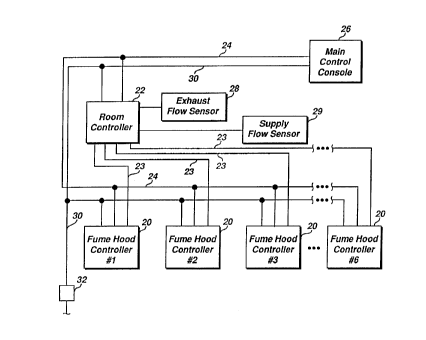
24 diagram is shown of several fume hood controllers 20 interconnected with a room
controller 22 and a main control console 26. The fume hood controllers 20 are
26 interconnected with the room controller 22 and the main control console 26 in a
27 local area network illustrated by line 24 which may be a multiconductor cable or
28 the like. The room controller and the main control console 26 are typically part
29 of the building main HVAC system in which the laboratory rooms containing the
2 1 9 7 4 ¦ ~
fume hoods are located. The fume hood controllers 20 are provided with power
2 through line 30, which is at the proper voltaae via a transformer 32 or the like.
3 The room controller 22 preferably is of the type which is at least
4 capable of providing a variable air volume to the room, and may be a Landis &
Gyr, Inc. System 600 Building Automation System (BAS) controller. The room
6 controller 22 is capable of communicating over the LAN lines 24. The room
7 controller preferably is a System 600 BAS controller and is a commercially
8 available controller for which e~ensi~/e documentation exists. The User Reference
9 Manual for the System 600 BAS controller is specifically incorporated by reference
herein.
11 The room controller 22 receives signals via lines 23 from each of the
12 fume hood controllers 20 that provides an analog input signal indicating the volume
13 of air that is being exhausted by each of the fume hood controllers 20 and a
14 comparable signal from an exhaust flow sensor 28 that provides an indication of
the volume of air that is being e~ch~ te~ through the main exhaust system apart
16 from the fume hood exhausts. These signals coupled with a signal from a supply
17 flow sensor 29 which indicates the flow of air coming into the room enables the
18 room controller to calculate the difference of the total into the room and the total
19 flow being e~h~-lcte~l from the room and m~int~in a preset difference. This enables
the differential pressure within the room to be controlled at a slightly lower
21 pressure than a reference space outside the room, i.e., preferably within the range
22 of about 0.01 to about 0.1 inches of water, which results in the desirable lower
23 pressure of the room relative to the reference space. However, it is not so low that
24 it prevents persons inside the laboratory room f~om opening the doors to escape in
the event of an emergency, particularly if the doors open outwardly from the room.
26 Also, in the event the doors open inwardly, the differential pressure will not be so
27 great that it will pull the door open due to excessive force being applied due to
28 such pressure.
29 Referring to FIG. 2, a fume hood controller 20 is illustrated with its
21 q7~
input and output connector ports being identified, and the fume hood controller 20
2 is connected to an operator panel 34. It should be understood that each fume hood
3 will have a fume hood controller 20 and that an operator panel will be provided
4 with each fume hood controller. The operator panel 34 is provided for each of the
S fume hoods and it iS interconnected with the fume hood controller 20 by a line 36
6 which preferably comprises a multi-conductor cable having eight conductors. The
7 operator panel has a connector 38, such as a 6 wire RJ11 type telephone jack for
8 example, into which a lap top personal computer or the like may be connected for
9 the purpose of inputting information relating to the configuration or operation of
10 the fume hood during initial in~t~ tion, or to change certain operating parameters
11 if necessary. The operator panel 34 is preferably mounted to the fume hood in a
12 convenient location adapted to be easily observed by a person who is working with
13 the fume hood.
14 The fume hood controller operator panel 34 preferably includes aliquid crystal display 40, which when selectively activated, provides the visual16 indication of various aspects of the operation of the fume hood, including three
17 digits 42 which provide the average face velocity. The display 40 illustrates other
18 conditions such as lo~- face velocity, high face velocity and emergency condition
19 and an indication of controller failure. The operator panel may have an audible
hom 44 and an emergency purge switch 46 which an operator can press to purge
21 the fume hood in the event of an accident. The operator panel has two auxiliary
22 switches 48 which can be used for various customer needs, including day/night
23 modes of operation. It is contemplated that night time mode of operation would
24 have a different and preferably reduced average face velocity, presumably because
no one would be working in the area and such a lower average face velocity would26 conserve energ~. An alarm silence switch 50 is also preferably provided to27 extinguish the hom or visible alarm.
28 Fume hoods come in many different styles, sizes and configurations,
29 including those ~hich have a single sash door or a number of sash doors, with the
21974~ I
sash doors being moveable vertically, horizontally or in both directions.
2 Referring to FIG. 3, there is shown a fume hood, indicated generally
3 at 60, which has a vertically operated sash door 62 which can be moved to gain
4 access to the fume hood and which can be moved to the substantially closed
position as shown. Fume hoods are generally designed so that even when a door
6 sash such as door sash 62 is completely closed, there is still some amount of
7 opening into the furne hood, such as opening 63, through which air can pass. This
8 opening 63 is generally referred to as the by-pass area and it can be determined so
9 that its effect can be taken into consideration in controlling the flow of air into ~e
fume hood. Some types of fume hoods have a by-pass opening that is located
11 above the door sash while others are below the same. In some fume hoods, the
12 first amount of movement of a sash door will increase the opening at the bottom
13 of the door shown in FIG. 3, for example, but as the door is raised, it will merely
14 cut off the by-pass opening so that the size of the total opening of the fume hood
is m~int~ined relatively constant for perhaps the first one-fourth amount of
16 movement of the sash door 62 through its course of travel and ignoring any effect
17 of a grille 65 which is provided to overlie the by-pass area.
18 Other types of fume hoods may include several horizontally moveable
19 sash doors 66 such as shown in FIGS. 4 and 5, with the doors being movable in
upper and lower pairs of adjacent tracks 68. When the doors are positioned as
21 shown in FIGS. 4 and 5, the fume hood opening is completely closed and an
22 operator may move the doors in the horizontal direction to gain access to the filme
23 hood. Both of the fumes hoods 60 and 64 have an exhaust duct 70 which generally
24 extends to an exhaust system which may be that of the HVAC apparatus previously
described.
26 Referring to FIG. 6, there is shown a combination fume hood which
27 has horizontally movable doors 76 which are similar to the doors 66, with the fume
28 hood 74 having a frame structure 78 which carries the doors 76 in suitable tracks
29 and the frame structure 78 is also vertically movable in the opening of the fume
- 21 9741 ~i
hood.
2 The illustration of FIG. 6 has portions removed as shown by the
3 break lines 73 which is intended to illustrate that the height of the fume hood may
4 be greater than is otherwise shown so that the frame structure 78 may be raised
sufficiently to permit adequate access to the interior of the fume hood by a person.
6 There is generally a by-pass area which is identified as the vertical area 75, and
7 there is typically a top lip portion 77 which may be approximately 2 inches wide.
8 This dimension is preferably defined so that its effect on the calculation of the
9 open face area can be taken into consideration.
While not specifically illustrated, other combinations are also
11 possible, including multiple sets of vertically moveable sash doors positioned
12 adjacent one another along the width of the fume hood opening, with two or more
13 sash doors being vertically moveable in adjacent tracks, much the same as
14 residential casement windows.
In accordance with an important aspect of the fume hood controller
16 20, it is adapted to operate the fume hoods of various sizes and configuratiorls as
17 has been described, and it is also adapted to be incorporated into a laboratory room
18 where several fume hoods may be located and which may have exhaust ducts19 which merge into a common exhaust manifold which may be a part of the building
HVAC system. A fume hood may be a single self-contained installation and may
21 have its own separate exhaust duct. In the event that a single fume hood is
22 installed, it is typical that such an installation would have a variable speed motor
23 driven blower associated with the exhaust duct whereby the speed of the motor and
24 blower can be variably controlled to thereby adjust the flow of air through.the
fume hood. Alternatively, and most typically for multiple fume hoods in a single26 area, the exhaust ducts of each fume hood are merged into one or more larger
27 exhaust manifolds and a single large blower may be provided in the manifold
28 system. In such types of installations, control of each fume hood is achieved by
29 means of separate darnpers located in the exhaust duct of each fume hood, so that
219741 ~
variation in the flo~v can be controlled by appro~-iately positioning the damper2 associated with each fume hood.
3 The fume hood controller is adapted to control virtually any of the
4 various kinds and styles of fume hoods that are cornmercially available, and to this
end, it has a number of input and output ports (lines, connectors or connections,
6 all considered to be equivalent herein) that can be connected to various sensors that
7 may be used with the controller. As shown in FIG. 2, it has digital output or D0
8 ports which interface with a digital signal/analog pressure transducer with an
9 exhaust damper as previously described, but it also has an analog voltage output
port for controlling a variable speed fan drive if it is to be installed in that manner.
11 There are five sash position sensor ports for use in sensing the position of both
12 hon70ntally and vertically moveable sashes and there is also an analog input port
13 provided for connection to an exhaust air flow sensor 49. A digital input port for
14 the emergency switch is provided and digital output ports for outputting an alarm
horn signal as well as an auxiliary signal is provided. An analog voltage output16 port is also provided for providing a volume of flow signal to the room controller
17 22. In certain applications where the exhaust air flow sensor is not provided, a
18 ~vall velocity sensor indicative of face velocity may be utilized and an input port
19 for such a signal is provided, but the use of such sensors is generally considered
to be less accurate and is not the preferred embodiment. With these various input
21 and output ports, virtually any type of fume hood can be controlled in an effective
22 arld efficient manner.
23 To determine the position of the sash doors, a sash position sensor is
24 provided adjacent each movable sash door and it is generally illustrated in FIGS.
7, 8 and 9. Referring to FIG. 8, the door sash position sensor comprises an
26 elongated switch mech~ni~m 80 of relatively simple mechanical design which
27 preferably consists of a relatively thin polyester base layer 82 upon which is printed
28 a strip of electrically resistive ink 84 of a known constant resistance per unit
29 length. Another polyester base layer 86 is provided and it has a strip of electrically
219741 i
conductive ink 88 printed on it. The two base layers 82 and 86 are a&esively
2 bonded to one another by two beads of adhesive 90 located on opposite sides of
3 the strip. The base layers are preferably approximately five-thousandths of an inch
4 thick and the beads are approximately two-thousandths of an inch thick, with the
S beads providing a spaced area between the conductive and resistive layers 88 and
6 84. The switching me~h~ni~m 80 is preferably applied to the fume hood by a layer
7 of adhesive 92. --
8 The polyester material is sufficiently flexible to enable one layer to
9 be moved toward the other so that contact is made in response to a preferably
spring biased actuator 94 carried by the appr~liate sash door to which the strip is
11 placed adjacent to so that when the sash door is moved, the actuator 94 moves
12 along the switching mech~ni~m 80 and provides contact between the resistive and
13 conductive layers which are then sensed by electrical circuitry to be described
14 which provides a voltage output that is indicative of the position of the ~ct l~tor 94
along the length of the switching means. Stated in other words, the actuator 94 is
16 carried by the door and therefore provides an electrical voltage that is indicative
17 of the position of the sash door.
18 The actuator 94 is preferably spring biased toward the switching
19 mechanism 80 so that as the door is moved, sufficient pressure is applied to the
switching means to bring the two base layers together so that the resistive and
21 conductive layers make electrical contact with one another and if this is done, the
22 voltage level is provided. By having the switching means 80 of sufficient length
23 so that the full extent of the travel of the sash door is provided as shown in FIG.
24 3, then an accurate determination of the sash position can be made.
It should be understood that the illustration of the switching
26 mechanism 80 in FIGS. 3 and 5 is intended to be diagr~mm~tic, in that the
27 switching mech~ni~m is preferably actually located within the sash frame itself and
28 accordingly would not be visible as shown. The width and thickness dimensions
29 of the switching mechanism are so small that there is little interference with the
- 2 1 974 1 ~
operation of the sash door. The actuator 94 can also be placed in a small hole that
2 may be drilled in the sash door or it may be attached externally at one end thereof
3 so that it can be in position to operate the switch 80. In the vertical moveable sash
4 doors shown in FIGS. 3 and 6, a switching mech~ni~m 80 is preferably provided
in one or the other of the sides of the sash frame, whereas in the fume hoods
6 having horizontally movable doors, it is preferred that the switching mech~ni~m 80
7 be placed in the top of the tracks 68 so that the switching me~h~ni~m 80 is out of
8 the operator's way.
9 Turning to FIG. 9, the preferred electrical circui'ay which generates
the position indicating voltage is illustrated, and this circuitry is adapted to provide
11 two separate voltages indicating the position of two sash doors in a single track.
12 With respect to the cross-section shown in FIG. 5, there are two horizontal tracks,
13 each of which carries two sash doors and a switching mesh~ni~m 80 is provided
14 for each of the tracks as is a circuit as shown in FIG. 9, thereby providirig a
distinct voltage for each of the four sash doors as shown.
16 The switching means is preferably applied to the fume hood with a
17 layer of adhesive 92 and the actuator 94 is adapted to bear upon the switching
18 means at locations along the length thereof. Referring to FIG. 7, a diagr~mm~tic
19 illustration of a pair of switching means is illustrated such as may occur with
respect to the two tracks shown in FIG. 5. A switching mech~ni~m 80 is provided
21 with each track and the four arrows illustrated represent the point of contact created
22 by the actuators 94 which result in a signal being applied on each of the ends of
23 each switching means, with the m~gnittl~e of the signal representing a voltage that
24 is proportional to the distance between the end and the nearest arrow. Thus, a
single switching mech~ni~m 80 is adapted to provide position indicating signals for
26 two doors located in each track. The circuitry that is used to accomplish the
27 voltage generation is shown in FIG. 9 and includes one of these circuits for each
28 track. The resistive element is shown at 84 and the conductive element 88 is also
29 illustrated being connected to ground with two arrows being illustrated, and
- 2 1 974 1 1
represented the point of contact between the resistive and conductive elements
2 caused by each of the actuators 94 associated with the two separate doors. The3 circuitry includes an operational amplifier 100 which has its output connected to
4 the base of a PNP transistor 102, the emitter of which is connected to a source of
5 positive voltage through resistor 104 into the negative input of the operational
6 amplifier, the positive input of which is also connected to a source of positive
7 voltage of preferably approximately five volts. The collector of the transistor 102
8 is connected to one end of the resistive element 84 and has an output line 106 on
9 which the voltage is produced that is indicative of the position of the door.
10The circuit operates to provide a constant current directed into the
11resistive element 84 and this current results in a voltage on line 106 that is propor-
12 tional to the resistance value between the collector and ground which changes as
13 the nearest point of contact along the lesi~ ce changes. The operational amplifier
14 operates to attempt to drive the negative input to equal the voltage level on the
15 positive input and this result~ in the current applied at the output of the operational
16 amplifier varying in direct proportion to the effective length of the resistance strip
17 84. The lower portion of the circuitry operates the same way as that which has
18 been described and it similarly produces a voltage on an output line 108 that is
19 proportional to the distance between the connected end of the resistance element
20 84 and the point of contact that is made by the actuator 94 associated with the
21 other sash door in the track.
22 Referring to the composite electrical schematic diagram of the
23 circuitry of the fume hood controller, if the separate drawings FIGS. lOa, lOb, lOc,
24 lOd and lOe are placed adjacent one another in the manner shown in FIG. 10, the
25 total electrical schematic diagram of the fume hood controller 20 is illustrated. The
26 operation of the circuitry of FIGS. lOa through lOe will not be described in detail.
27 The circuitrv is driven by a microprocessor and the important algorithms that carry
28 out the control functions of the controller will be hereinafter described. Referring
29 to FIG. lOc the circuitry includes a Motorola MC 68HCll microprocessor 120
'- 21974l 1
which is clocked at 8 MHz by a crystal 122. The microprocessor 120 has a
2 databus 124 that is connected to a tri-state buffer 126 (FIG. 10d) which in turn is
3 connected to an electrically programrnable read only memory 128 that is also
4 connected to the databus 124. The EPROM 128 has address lines A0 through A7
connected to the tri-state buffer 126 and also has address lines A8 through A14
6 connected to the microprocessor 120.
7 The circuitry includes a 3 to 8-bit multiplexer 130, a data latch 132
8 (see FIG. 10d), a digital-to-analog converter 134, which is adapted to provide the
9 analog outputs indicative of the volume of air being exhausted by the fume hood,
which information is provided to room controller 22 as has been previously
11 described with respect to FIG. 2. Referring to FIG. 10b, an RS232 driver 136 is
12 provided for transmitting and receiving information through the hand held terminal.
13 The circuitry illustrated in FIG. 9 is also shown in the overall schematic diagrams
14 and is in FIGS. 10a and 10b. The other components are well known and therefore
need not be otherwise described.
16 As previously mentioned, the monitoring apparatus of the present
17 invention is particularly adapted to be incorporated in a fume hood controller of
18 the type disclosed in U.S. Patent 5,470,275 and in that regard, the specification and
19 drawings relating to that patent are specifically incorporated by reference herein.
One of the significant advantages of the present invention is that the controller
21 executes its control scheme in a repetitive and extremely rapid manner. The
22 microprocessor samples flow signal information as well as sash door position
23 signals at a speed of approximately one sample per 100 milliseconds during
24 operation. The result is that rapid responsive control action is accomplished as is
desired. Also, by virtue of the speed of sampling of the sash positions, it is
26 possible to calculate the speed of movement of the sashes as they are moved by an
27 operator ~vith extreme accuracy. Also, because of the frequent sampling, the
28 presence of any movement is immediately detected and the speed of movement can
29 be calculated by the microprocessor 120. It should be realized that with the fast
14
219741 ~
clock present in the microprocessor, the speed of movement of any sash door can
2 be calculated virtually within 200 milliseconds. It is preferred that the sensed
3 speed of movement of a sash door during an opening thereof will be compared to
4 a predetermined value, which is approximately 1.5 feet per second. If opening
S speed of movement of the sash equals or exceeds approximately 1.5 feet per
6 second, then the microprocessor 120 will issue an alarm signal for creating either
7 an audible alarm, a visible alarm or both.
8 It is preferred that an alarm be an intermittent alarm sound via the
9 alarm 44 which will alert the operator to slow the movement of the sash door
during its opening. ~Itern~tively, it may be desirable to ilhlmin~te one or more of
11 the visible display characters on the operator panel 34 by blinking them.
12 It is also within the scope of the present invention that the issuance
13 of the alarm signal may be used to activate a braking force to the sash to slow the
14 movement of the same. The braking force may comprise a pressure applying pad
to a surface of the sash, with the pad being connected to a solenoid that is
16 energized by the alarm signal.
17 It should be understood that with multiple sash doors, movement of
18 any one door can have the effect of increasing or decreasing the uncovered size of
19 the opening, and therefore the calculation of the uncovered size of the opening
must be made to determine if the movement is increasing the size of the opening
21 or not. However, for multiple sash door fume hoods, it is within the scope of the
22 present invention to generate an alarm whenever one of the doors is moved at a
23 fast speed even if the size of the opening is not increasing.
24 From the foregoing detailed description, it should be appreciated that
a fume hood controller has been shown and described that has superior capabilities
26 in being able to accurately monitor the speed of movement of one or more sash
27 doors of a laboratory fume hood, and generate an alarm if the speed of movement
28 equals or exceeds a predetermined value. The alarm alerts an operator that the
29 opening of the sash door should be slowed to minimi7e the possibility of creating
- 2197~
-
a leakage condition.
2 While various embodiments of the present invention have been shown
3 and described, it should be understood that various alternatives, substitutions and
4 equivalents can be used, and the present invention should only be limited by the
S claims and equivalents thereof.
6 Various features of the present invention are set forth in the following
7 claims.
16