Note: Descriptions are shown in the official language in which they were submitted.
~ WO96104814 2 1 9 7 4 7 ~ r~ sc.
PLT~TOR FOR ~PPLYT~G ~ FL~Tn
The present invention relates to an ~rrl; r~tor for
applying various fluid products, for example for
applying colorants to hair.
The ~prl~ratinn of treatment fluids to hair
requires skill and practice if good results are to be
achieved. The quality of the result is often de~e1-de~1t
upon the skill and precision with which the treatment
is applied, and so an applicator which helps a
hairdresser to control the application of a fluid is
beneficial in achieving a desired result.
It is already known for a hairdresser to place a
~Le~L~ treatment fluid into a plastic cn~t~;n~r
provided with a nozzle through which the fluid may be
squeezed on to the hair. Although this method of
application is convenient and less messy than applying
the fluid from a bowl using a brush, if a very fine
nozzle is used to achieve a precise line of treatment,
the rate at which fluid can be ~Yr~ d from such a
nozzle makes the application slow. Also, it can be
J ~ 2~97474 '
~,
difficult to ensure that the treatment is applied to the correct
parts of the hair. ~
- DE-A-3743713 discloses a hairbrush having a plurality of
substantially parallel bristles some of which are hollow whereby
a treatment fluid from a container embodied in the brush can be
fed into the user's hair.
It would be desirable to be able to provide an alternative
form of fluid applicator which overcomes some=at least of the
problems encounterea with current forms of applicator, and-in
particular which enables accurate control in the application of
the fluid to a substrate.
According to the present invention, there is provided an
applicator for applying a fluid to a substrate comprising a
reservoir for containing a treatment fluid, at least two nozzles
spaced apart from one another and generally parallel with one
another, and a passage connecting each of said nozzles to the
reservoir, characterised in that the nozzles are each movable
between an open poeition in which a bore therethrough
communicates with the interior of the reservoir, and a closed
position in which flow of fluid therethrough from the reservoir
is prevented
The provision of at least two spaced apart nozzles allows
fluid to be applied to at least two sepa-rate areas
simultaneously, which has particular advantages when used to
apply colour in the form of "highlightsN or ~lowlights~ to hair,
because several narrow bands of colour usually give a more
natural-looking result than a single wider band.
Although the invention is described in terms of-its
AMENDED ~hEE~
, ~ _ , . .. , . , . -
2 1 97~74
. .
suitability for use in applying hair treatments, its advantages
may be beneficial in other uses such as in the application of
decorative paint effects.
The reservoir may be an integral part of a complete
container such as a tube or bottle in which the treatment fluid
is contained. The regervoir is, however, preferably readily
~t~ hle from such a container so that it may be cleaned easily
between applications. Most preferably, it is attached to and
detachable from the container, for example by means of a screw-
threaded connection or by a ridge provided on one of the
reservoir and the ~nnt~inPr for engagement in a groove provided
on the other of the reservoir and the ~nt~in~r.
The applicator may be used with a wide variety of containers
and fluid expulsion means. For example one type of suitable
container has a piston-like plate which may be caused to move
j towards the nozzles to force the fluid contained in the ~nnt~in~r
out of the nozzles by depressing a plunger to which the plate is
attached, as in a syringe, or by activation of a sprung mechanism
by depressing a trigger, for example. Alternatively, some form
of pressured c~nt~;n~r may be used from which fluid may be
expelled through the nozzles by applying gas pressure within the
c~nt~;n~r~
A preferred type of c~nt~;n~r is a flexible tube or bottle
from which fluid may be expelled by squeezing.
The reservoir is connected to at least two nozzles through
which fluid may be expelled from the reservoir. Preferably at
least three nozzlesare provided, and most preferably six to ten
nozzles, spaced apart from each other in a direction transverse
AME~IDED SI~EET
~ 2 197474
to the axes of the nozzle exits
The nozzles may each be opened and closed independently of
one another The nozzles are preferably pivotal between their
open and closed positions ie of a type which are joined to the
reser~oir by means of a pivotal connection whereby they may be
closed by pivoting or folding them towards the reservoir so that
the fluid passage therethrough is interrupted, or opened by being
positioned to extend from the reservoir, so that the fluid
passage between the reser~oir and the no=z=zle=~
AMENDED SI~EET
W096/0481~ P~1/~_~5~
~ 21 97474
.
becomes ~S5~nt; ~1 1y linear and uninterrupted By these
means, the amount of fluid applied and the width of a
section of hair to be treated may be controlled by
opening the required number of nozzles. Also, the
fluid may be applied in a number of narrow stripes
which may be required 8p~r; ~; r~l ly when carrying out
certain types of treatment, for example putting
highlights in hair.
Preferably the applicator further comprises a
generally elongate spreader located transversely to the
axes of the nozzles and in ciose proximity to said
nozzles. The presence of a spreader allows the person
applying the fluid greater control over application of
the fluid, because the spreader may be braced against
the part of the substrate which is being treated.
The elongate spreader may be a solid bar,
optionally tapered away from the reservoir.
Preferably, however, the spreader comprises a comb
which has relatively fine teeth. In this form, the
comb and nozzles are preferably arranged so that the
nozzles each discharge fluid between two adjacent teeth
of the comb. Alternatively, the spreader may comprise
WO 96/04814 PCT/GB95/01901
21 ~7474 ~!
a bru8h, in which form it may be particularly suitable
for applying paint, especially for producing decorative
effects.
The spreader is preferably joined to an external
wall of the reservoir in such a way that it is lnrl;nP~
towards the axes of the open nozzles preferably at an
angle of between 30~ and 60~ to the axes of the
nozzles. The spreader may touch the ends of the
nozzles. The spreader may, optionally, be adapted to
be readily ~p~rh~hle from and att~rh~hlP to the
reservoir, so that it can be removed for cleaning or
for storage, for example. ~t may, for example, have a
tongue running along an edge which may frictionally
engage in a corrP~p~n~; n~ slot in the reservoir.
The appl; ratnr i9 preferably made from a suitable
plastics material, such as polypropylene. The
reservoir, nozzles and spreader, if present, are
preferably relatively rigid. The rnnt~;n~r, reservoir
and nozzles are preferably transparent or translucent,
80 that the amount and compo8ition of the fluid
r~nt~;nP~ therein may be viewed from the outside.
The reservoir and/or a rrnt~;nPr to which it is
WO96/04814 PCT/Gs9~0l901
21 97474
secured may be marked to indicate the volume of fluid
~ nnn~AinPd therein. Preferably the r~rk~ng~ are
graduated along a substantial part of the cnntAinPr or
reservoir and, most preferably, they are marked in 8uch
a way that they may indicate the volume of fluid in the
n~n~A;nPr and/or reservoir both when the applicator is
uppermost and when it is point; nS downwards, which
would normally be its position when in use.
The container may optionally contain a heavy bar,
bead or the like to agitate the treatment fluid on
shaki~g of the cnn~A;npr~
One preferred form of the invention will now be
described, by way of example only, and with re~erence
to the An~ "ying drawings of which:
Fig. 1 is a plan view of a hair treatment
applicator according to the invention;
Fig. 2 shows a reservoir of an applicator
accordiny to the invention with the nozzles
removed and a spreader attached; and
Fig. 3 is a longitudinal section through an
applicator according to the invention in its
operative position.
Wo96/04814
21 97474
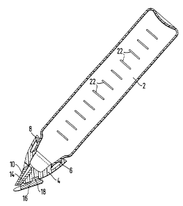
The hair treatment applicator shown in Fig. 1
comprises a cnnt~inPr 2 formed of a flexible
transparent plastics material, and a reservoir 4, also
transparent but more rigid than the ~nnt~;n~r 2. The
reservoir 4 is secured to the ~nnr~in~r 2 by means of a
ridge 6 around the circumference of the cnn~1n~r 2 the
underside of which is engaged by projections 8 formed
on the opposed iDner walls of the reservoir. The
~ ~n~q 2 and 4 may be pushed together into positive
engagement and subsequently separated by pulling them
apart so as to disengage the projections 8 from the
ridge 6.
Alternatively the reservoir 4 may be secured to
the rnn~inPr 2 by means of an ~tPrn~l screw-thread
provided on the cnnr~;nPr 2 co-operating with a
corr~Rp~n~ing ;n~rn~l screw-thread provided in the
reservoir 4.
The reservoir 4 is provided with six nozzles 10
each pivotal within an associated groove 12 in.the
reservoir 4 between an open position, in which the
nozzle extends longitn~;n~lly of the ~ppl;ratnr and the
bore 14 therethrough communicates with the interior of
WO96/04814 P~l,~ ,~ 13~l
21 97474
the reservoir 4~ and a closed position in which the
~ nozzle 10 extends outwardly of the reservoir 4 and the
bore 14 is disconnected from the intexior of the
reservoir 4.
A comb or spreader 16 i9 releasably mounted to the
resexvoir 4, for example by means of a tongue 18 on the
comb 16 being slidably received in a corx~Rpnn~;n~
gxoove 20 in the reservoir 4, the plane of the comb 16
making an angle of about 40~ to the axes of the
0 ~nnt~in~r 2 ag best seen in Fig. 3.
Alternatively, the comb 16 may be mounted to the
reservoir 4 by means of a projection provided on the
comb 16 which is a friction push-fit into a
corresponding recess in the reservoir 4.
lS In use, a quantity of hair treatment fluid, such
as a colorant, is placed into the ~nnt~;n~r 2, and the
re3exvoir 4 is secured over the end of the cn~t~inDr 2
to close it. At lea8t one nozzle 10 is opened, the
number of open nozzles 10 governing the width of the
strip of fluid which is applied. The section of hair
to be treated i9 then separated from the rest of the
hair, the applicator is held in the position shown in
w096/048l4 .~
21 ~7474 1--
Fig. 3 and the comb 16 is drawn through the hair
section from above as the cnnt~inpr 2 is squeezed
gently to expel fluid through the nozzles 10. The com~
16 both stabilises the section of hair, ~ ng the
even application of fluid along the section, and also
helps the fluid to spread evenly across the section
being treated.
As the treatment cnnt; nnP~ the user can easily
monitor the amount of fluid L~ ;n;ng in the rnnt~;nPr
by referring to a graduated scale 22 upon the side.
There may be two graduated scales, one on each side of
the cnnt~;nPr, one for the applicator in an upright
position, and the other for the apFl;~tnr in an
inverted position.
When the treatment is finished, the reservoir 4
may be separated from the ~nnt~;nPr 2 so that it can be
cleaned ready for a subse~uent treatment or to allow
the ~n~tAin~r to be refilled.
The reservoir 4 and/or the nnnt~;n~r 2 may,
however, be ;ntPn~pd to be ~;~pnsPd of after one use
only. It may, for example, be aesirable to supply
standard pre-mixed treatments in a number of nnnt~;nPr8
WO96/04814 P~ ol
2~ 97474
11
2 which may be fitted to a reservoir 4 just before the
~ treatment is applied. Ma~ytreatments must, however be
mixed freshly shortly before application, in which case
a user would fill the c~n~1n~r 2 when the treatment
had been prepared.
As will be appreciated, the applicator according
to the 1 nv~nt 1 ~n improves the ability of the user to
apply a hair treatment in a controlled manner, to the
extent for example that colouring only a discrete
section of hair is made easier than with applicators
available hitherto. Using the applicators illustrated
in the drawings, it is possible to apply fine lines of
highlighting treatment relatively ~uickly and easily
compared with using existing applicators.
. . .