Note: Descriptions are shown in the official language in which they were submitted.
21 q7528
'
1 DECODER WITH AN ERROR CONTROL ADAPTIVELY APPLIED
ON THE BASIS OF THE ESTIMATED POSITION
OF A SLOT IN A FRAME
BACKGROUND OF THE INVENTION
Field of the Invention
The present invention relates to a decoder
for decoding coded data, which is preferably applied to
a digital control ch~nnel receiver of a TDMA cellular
system in accordance with the North American Standard
of TDMA (Time Division Multiple Access), such as TIA
(Telecommunications Industry Association)-TDMA (IS-136).
Description of the Background Art
The digital ch~nnels of the TDMA cellular
system in accordance with the North American Standard
include digital control ch~nnels (abbreviated to DCCHs
herein- below) for conveying information required for
call control from a base station to mobile stations,
and digital traffic ch~nn~ls (abbreviated to DTCs
hereinbelow) for conveying user's information.
The down link communications from the base
station to the mobile stations using the DCCHs is
carried out on a superframe basis. The superframe
consists of 32 time slots in full-rate transmission,
and 16 time slots in half-rate transmission.
Information describing the position of a slot in the
superframe is called a superframe phase (abbreviated
to SFP hereinbelow). The SFP consists of an 8-bit code
of modulo 32 (although a 5-bit code is enough, the
8-bit code is used for the purpose of simplifying a
processing circuit). In the half-rate superframe,
2t97528
1 only odd- or even-nembered slots are used.
As shown in FIG. 2, the superframe consists
of a fast broadcast channel (abbreviated to F-BCCH
hereinbelow), an extended broadcast channel (abbre-
viated to E-BCCH hereinbelow), a short message service
broadcast ch~nn~l ( abbreviated to S-BCCH hereinbelow),
reserved slots and an Smsch, Pch and Arch ch~nnels
(abbreviated to SPACHs hereinbelow).
The F-BCCH is a ch~nn~l used for
transmitting known information such as structure
variables of the DCCHs, parameters needed for access
to a system, or the like. Parameters NTHl, NTH2, and
DVCC which will be described later are transmitted from
the base station to the mobile stations over the
F-BCCH. The E-BCCH is used for transmitting
information less critical in time than that transmitted
over the F-BCCH. The S-BCCH is used for short message
broadcast services. The SPACHs are used for calling or
transmitting orders (PCH), responding to the access
from the mobile stations (ARCH), and point-to-point
short message services (SMSCH).
.
Although the number of the slots of the
F-BCCH, E-BCCH, S-BCCH and SPACHs differ from
superframe to superframe of respective frequencies
depending on the purpose (chiefly, whether they are
used for message services or waiting), the SFPs are
assigned in any superframes in such a fashion that
they change in ascending order from OOh (_ is a
hex~ecimal notation) to lFh in the order of F-BCCH,
E-BCCH, S-BCCH, reserved slots~ and SPACHs as shown in
- 2 i 97528
1 FIG. 2.
The SFP of the initial slot of the E-BCCH
(called NTH1 hereinbelow), and the SFP of the initial
slot of the SPACHs (called NTH2 hereinbelow) are
obtained by decoding the F-BCCH followed by analyzing
the obtained data.
As shown in part (A) of FIG. 3, each slot
(consisting of 324 bits) in the superframe consists of
a 28-bit synchronizing signal (SYNC), a 12-bit random
access control signal (shared control feedback: SCF),
130-bit data (DATA), a 12-bit coded SFP (called CSFP
below), 130-bit data (DATA), a 10-bit random access
control signal (SCF), and 2-bit reserved bits (R).
As mentioned above, the 8-bit SFP is coded
into 12-bit CSFP. More specifically, the SFP is coded
into a (12, 8) Hamming code, and the resultant 4-bit
parity bits are inverted and added to the SFP to form
the CSFP. Accordingly, the mobile station can find the
location of the current slot in the superframe by
obt~i n i ng the SFP by decoding the CSFP.
As shown in part (B) of FIG. 3, the data
section (DATA) consists of information which is the
body of the transmitted data, a CRC which is check bits
for error detection or error correction of the
information, and a tail bit representing the end of the
data section.
The methods of calculating the CRC of the
data sections at a receiver (mobile station) can be
2t 97528
1 classified into three types A, B and C depending on the
types of chAnnels to which the slot belongs. More
specifically, the calculating methods of the CRC are
classified into three types A, B and C as shown in FIG.
4 depending on the value of a check code (abbreviated
to DVCC hereinbelow) and whether or not the parity bits
are inverted when used. The DVCC determines the
generator polynomial used for calculating the CRC, and
varies depending on the frequency of the superframe.
The calculating method A is used for the slots
belonging to the F-BCCH, in which the DVCC with a value
zero is used, and the parity bits are inverted. The
calculating method B is used for the slots belonging to
the E-BCCH, S-BCCH and reserved slots, in which the
DVCC with a value designated by the base station (BS)
is used, and the parity bits are inverted. The method
C is used for the slots belonging to the SPACHs, in
which the DVCC with a value designated by the base
station is used, and the parity bits are not inverted.
The slots of the F-BCCH uses the DVCC with a
value zero because the value of the DVCC can be
obtained for the first time after analyzing the F-BCCH
data as in the case of the above-mentioned NTHl and
NTH2.
Thus, any of the calculating methods of the
CRC of the received data is used depending upon the
rhAnnPls to which the slots belong. Therefore, the
types of the ch~nn~ls ( classified in terms of the
calculating methods of the CRC) to which the slot
belongs must be recognized before performing decoding,
detection and correction of the received data in the
' 2197528
.
1 slot. Here, the types of the calculating methods of
the CRC are conventionally recognized by obtaining the
SFP of the slot by decoding the CSFP, and by comparing
the obtained SFP with the parameters NTH1 and NTH2.
There is the possibility in the conventional
method, however, that the type of the chAnnel to which
the slot belongs cannot be identified, and this will
degrade the decoding accuracy of the data. The reason
for this is as follows. As described above, the CSFP
employ a Hamming code. On the other hand, the data
section (DATA) uses convolutional codes. According to
the Recommendations to the digital channels of the TDMA
systems based on the North American Standard, the free
space distance of the convolutional codes is greater
than that of the Hamming code, which means that the
error correction performance of the convolutional codes
is greater than that of the Hamming codes. Thus, there
is the possibility that the CSFPs consisting of Hamming
codes cannot be correctly decoded, which will lead to
error in decoding, error detection and correction of
the received data (DATA). This will cause the
degradation in the decoding accuracy of the data.
That problem arises not only with the digital
control ch~nnels of the TDMA cellular system according
to the North American Standard, but also with other
digital communication systems which switch the error
control methods depending on the slot location in the
frame.
SUMMARY OF THE INVENTION
It is therefore an object of the present
21 97528
-
1 invention to provide a decoder which can achieve
correct error checking of the received data even if the
SFP (intra-frame position information) includes an
error.
According to an aspect of the present
invention, there is provided a decoder for receivng a
frame of coded data consisting of multiple slots which
include intra-frame position information indicating
position of the slots in the frame and decoding the
coded data, wherein appropriate one of error control
methods is adaptively applied depending on the position
of the slots in the frame, the decoder comprising:
intra-frame position estimation means for generating an
estimated value of the intra-frame position information
of a current slot in accordance with an estimated value
of the intra-frame position information of an
immediately preceding slot, and a fixed variation
amount per slot of the intra-frame position
information; intra-frame position information
synchronization means for establishing synchronization
between a received value and the estimated value of the
intra-frame position information; and applied method
determination means for determining an error control
method to be applied to the present slot in a
synchronous state of the received value and the
estimated value, in response to the estimated value of
the intra-frame position information of the current
slot generated by the intra-frame position estimation
means.
According to another aspect of the present
invention, there is provided decoder for receiving a
2t 97528
1 frame of coded data consisting of multiple slots,
wherein appropriate one of error control methods is
adaptively applied depending on the position of the
slots in the frame, the decoder comprising: plurality
of error control means, each corresponding to one of
the error control methods, for performing error control
operation of received data in a present slot by
applying each of the error control methods to the
current slot regardless of the position of the slots
in the frame; and application method selection means
for selecting a control result obtained by one of the
plurality of error control means as a control result
obtained by a control method assigned to the current
slot, considering control results obtained by the
plurality of error control means.
According to the first aspect of the present
invention, in the synchronous state in which the
received value of the intra-frame position information
is synchronized with the estimated value, the decoder
generates the estimated value of the intra-frame
position information of the present slot, and
determines the error control method to be applied to
the present slot on the basis of the estimated value of
the generated intra-frame position information. This
makes it possible to achieve the error control
operation for the received data correctly, even if an
error occurs in the received value of the intra-frame
position information in the synchronous state.
According to the second aspect of the present
invention, the decoder applies all types of error
control methods to the received data of the current
21 97528
1 slot regardless of the error control methods determined
depending on the location of the current slot in the
frame, and then selects the error control method to be
applied to the current slot based on these error
control results. This makes it possible to obtain the
result that would be obtained when the correct error
control operation is performed on the received data.
BRIEF DESCRIPTION OF THE DRAWINGS
- . 10 The objects and features of the present
invention will become more apparent from consideration
of the following detailed description taken in
conjunction with the accompanying drawings in which:
FIG. 1 is a flowchart showing the overall
processing in a first embodiment of a decoder in
accordance with the present invention;
FIG. 2 is a diagram showing an example of the
ch~nnel structure of the superframe on a digital
control ch~nnPl;
FIG. 3 is a diagram showing an example of the
data structure of a slot;
FIG. 4 is a diagram showing the relationships
between ch~nnPl types and CRC computing methods;
FIG. 5 is a schematic block diagram showing
the first embodiment of the decoder in accordance with
the present invention;
FIGS. 6A and 6B are a specific flowchart
useful for understanding the SFP synchronizing
processing in the first embodiment;
FIG. 7 is a specific flowchart, like FIG. 6,
useful for understanding the decoding processing of the
CSFP in the first embodiment;
FIG. 8 is a flowchart useful for understand-
21 97528
1 ing CRC calculating method A in the first embodiment;
FIG. 9 is a flowchart, like FIG. 8, useful
for understanding CRC calculating method B in the first
embodiment;
FIG. 10 is a flowchart, like FIG. 8, useful
for understanding CRC calculating method C in the first
embodiment;
FIG. 11 is a schematic block diagram, like
FIG. 5, showing a second or alternative embodiment of
the decoder in accordance with the present invention;
and
FIGS. 12A and 12B are a flowchart showing the
overall processing in the second embodiment.
DESCRIPTION OF THE PK ~:KK~:~ EMBODIMENTS
The invention will now be described with
reference to the accompanying drawings. The following
embodiments relate to the digital control ~h~nn~l S of
the TDMA cellular system based on the North American
Standard.
EMBODIMENT 1
Referring flrst to FIG. 5, schematically
showing a mobile station unit of an embodiment of the
present invention, the mobile station unit 10 generally
comprises an antenna ll, an RF (Radio Frequency)
processor 12, an analog-to-digital (A/D) converter 13,
a demodulator/ decoder 14, and a data processor 15.
A signal captured by the antenna 11 is fed
to the RF processor 12. The RF processor 12 tunes its
frequency to a desired ch~nnel to be received, and
carries out the AGC control. The received signal of
~ t 9 7 5 2 8
1 the desired ch~nnel is fed to the A/D converter 13
which converts it to a digital signal. The de-
modulator and decoder 14, which is composed of a
digital signal processor (DSP), for example, transforms
the input digital signal into a sequence of codes by
performing digital decoding, and provides the data
processor 15 with received data (corresponding to the
above-mentioned information) obtained by decoding the
code sequence, togéther with a flag ERDATA
representing whether the received data includes an
error (binary "1 n ) or not (binary "0"), received SFP
(called RSFP hereinbelow), and a flag ERSFP
representing whether the RSFP includes an error ("1")
or not ("0"). The data processor 15 is composed of a
central processing unit (CPU) that is apdapted to
process the received data or others supplied from the
demodulator and decoder 14. The data processor 15 in
the instant embodiment reversely provides the
demodulator and decoder 14 with the parameters DVCC,
NTHl and NTH2, which are obtained as a result of
analyzing the received data of the F-BCCH, together
with a flag FMODE representing whether a receiving mode
is a continuous receiving mode or an intermittent
,
receiving mode.
The continuous receiving mode and the
intermittent receiving mode are defined as follows:
The general sequence from turning on the power supply
(initial state) to entering the waiting state for being
called in the mobile station includes the following
three stages. (l) The mobile station, receiving the
F-BCCH, analyzes the known information included in the
F-BCCH to obtain information on the structure of the
1 0
21 97528
1 superframe including the DVCC, NTH1 and NTH2. (2) The
mobile station analyzes the data in the E-BCCH and
S-BCCH as needed. (3) The mobile station repeats
receiving the PCH in the SPACHs designated by the base
station, thus waiting for a call. Generally, the
reception of the PCH is carried out independently
without accompanying the reception of the other
~h~nn~ls to save power consumption.
Thus, at the sequences (l) and (2), it is
necessary to continually perform receiving processing
of the time slots of multiple ch~nnPls. This type of
receiving mode is called the continuous receiving mode.
On the contrary, at the sequence (3), it is necessary
to perform receiving processing of only the slot of the
designated PCH. This type of receiving mode is called
the intermittent receiving modé. The receiving
processing of the SPACHs can also be carried out in the
continuous receiving mode. The data processor 15
generates the flag FMODE representing whether the
receiving mode is the continuous receiving mode or
intermittent receiving mode in accordance with the
sequence step at that time, and provides it to the
demodulator and decoder 14.
Next, the featured processing of the
embodiment carried out by the demodulator and decoder
14 will now be described in its entirety with reference
to FIG. 1. In the following description, the
demodulator and decoder 14 and data processor 15 are
abbreviated to DSP 14 and CPU 15, respectively.
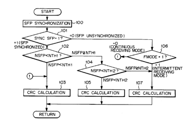
The DSP 14 carries out the processing as
21 97528
1 shown in FIG. 1 every time it receives the slot (at
20 ms interval). When the code sequence of a new slot
is obtained, the DSP 14 starts the processing, and
performs the synchronizing processing of the SFP at
step 100. Details of the SFP processing are shown in
FIGS. 6 and 7, which will be described later.
Subsequently, the DSP 14 decides whether the
synchronization of the RSFP is established or not on
the basis of a synchronization flag SYNC SFP at step
101. In other words, it decides whether the location
of the slot in the super frame is correctly recognized
or not.
If the synchronization is established with
the RSFP, the DSP 14 decides at step 102 whether or not
the value of a parameter NSFP, that is, the estimated
value of the SFP is smaller than the value of the
parameter NTH1 provided from CPU 15. The positive
result indicates that the present slot belongs to the
F-BCCH.
Hence, the DSP 14 carries out the CRC
computation (error control processing of the received
data) at step 103 in accordance with the CRC computing
method A for the F-BCCH, see FIG. 4, and then returns
to the main routine. Details of the CRC calculation in
accordance with the CRC calculating method A are shown
in FIG. 8, which will be described later.
If the negative result is obtained at the
foregoing step 102, the DSP 14 decides at step 104
whether or not the value of the NSFP is smaller than
l 2
21 97528 -
l the value of the NTH2 provided from the CPU 15. The
positive result here indicates that the present slot
belongs to one of the E-BCCH, S-BCCH and reserved
slots, in which case the DSP 14 carries out at step 105
the CRC calculating processing (error control
processing of the received data) in accordance with the
CRC calculating method B which has been determined
depending on the ch~nnel types, see FIG. 4, and returns
to the main routine. Detai-ls of the CRC calculation in
accordance with the CRC calculating method B are shown
in FIG. 9, which will also be described later.
The negative result at step 104 indicates
that the present slot belongs to the SPACHs, in which
case the DSP 14 carries out the CRC calculating
processing (error control processing of the received
data) in accordance with the CRC calculating method C,
see FIG. 4, at step 107, and then returns to the main
routine. Details of the CRC calculation in accordance
with the CRC calculating method C are shown in FIG. 10,
which will be described later.
If the DSP 14 decides that the synchroniza-
tion of the SFP has not yet been established at step
101, it makes decision of the content of the mode flag
FMODE at step 106. If the result indicates that the
mode is the continuous receiving mode ("0"), the DSP 14
carries out the CRC calculating processing (method A)
at step 103. On the contrary, if the mode is the
intermittent receiving mode (~1"), the DSP 14 carries
out the CRC calculating processing (method C) at the
foregoing step 107, and then returns to the main
routine.
2 1 97528
1 By thus changing the CRC calculating method
depending on the continuous receiving mode and the
intermittent receiving mode when the synchronization of
the SFP has not yet been established (that is, when the
SFP cannot be estimated), it is expected that the least
necessary information for call-standby processing can
be obtained.
1 4
2t 97528
1 In the intermittent receiving mode, i.e. in
the call standby state, it is enough for the DSP 14 to
receive the slot data of the PCH. Thus, the CRC
calculating method C is applied which is used for the
PCH (that is, for the SPACHs). On the other hand, in
the continuous receiving mode in an asynchronous state,
it is preferable that the operation be restarted from
acquiring the most important broadcast information,
that is, from receiving the F-BCCH data correctly.
Thus, the CRC calculating method A is applied which is
used for the F-BCCH.
Next, the details of the SFP synchronization
processing at step 100 will be described with reference
to the flowcharts in FIGS. 6A, 6B and 7. The values of
the parameters and flags immediately after the start
(in the initial state) of the receiving operation of
the mobile station unit are as follows. The initial
value of the synchronization flag SYNC SFP is "0",
which represents the asynchronous state. The initial
value of the mode flag FMODE is l-ON, which represents
the continuous receiving mode. The initial value of
the parameter NSFP (estimated SFP) is a freely set
value. The initial value of the parameter NOKSFP,
which represents the number of consecutive slots in
which the NSFP (estimated SFP) agrees with the RSFP
(received SFP), is zero. The initial value of the
parameter NERSFP which represents the number of
consecutive erroneous slots of the parameter RSFP is
zero.
The DSP 14, entering the synchronization
processing of the SFP, carries out decoding of the
1 5
21 97528
1 CSFP at step 200.
FIG. 7 illustrates the details of the
decoding of the CSFP. In the CSFP decoding, the DSP 14
inverts the logic levels of the parity bits
corresponding to the lower four bits of the 12 bits at
step 300. Subsequently, the DSP 14 carries out at step
301 (12, 8) Hamming decoding of the 12 bits whose
parity bits have been inverted, thereby recovering the
SFP (RSFP because they are recovered from the received
signal), and decides whether an error is detected or
not at step 302. If any error is detected here, the
DSP 14 sets the RSFP error flag ERSFP to "1" at step
303 and returns to the main routine. If no error is
detected, the DSP 14 sets the RSFP error flag ERSFP to
"0" at step 304, and returns its processing to step 201
of FIG. 6.
By thus calculating the decoding of the CSFP,
the DSP 14 updates the NSFP (estimated SFP) up to now
to the NSFP for the current slot at step 201.
Specifically, the DSP 14 adds to the NSFP up to now a
fixed parameter STEPSFP whose value is one at the full
rate, and two at the half rate, thereby updating the
NSFP up to now to the NSFP for the present slot. The
DSP 14 can decide whether the rate is the full rate or
half rate by the information included in the F-BCCH.
Alternatively, the DSP 14 can decide it by checking the
SYC pattern at every 20 ms interval, because the same
SYC pattern is repeated every 20 ms at the full rate,
and every 40 ms at the half rate.
Subsequently, the DSP 14 decides the content
1 6
21 97528
1 of the current SFP synchronization flag SYNC SFP at
step 202. That is, it decides whether or not the
synchronization of the SFP has been established at the
immediately preceding slot.
If the synchronization has been established,
the DSP 14 decides whether or not the RSFP of the
present slot includes an error on the basis of the
content of the RSFP error flag ERSFP at step 203. If
there is no error, the DSP 14 further decides whether
or not the RSFP agrees with the NSFP at step 204. If
the two agree with each other, the DSP 14 returns the
consecutive error slot number parameter NERSFP to its
initial value zero at step 205, and returns to the main
routine to transfer to the processing at the foregoing
step 101.
In this case, since the synchronization of
the SFP has been established and the received value of
the SFP agrees with its estimated value, the processing
of the step 102 and thereafter is carried out. Thus,
the CRC calculating method A, B or C is correctly
applied in accordance with the type of the ch~nnel to
which the present slot belongs.
On the other hand, if the DSP 14 decides
that the RSFP includes an error at step 203, or that
although there is no error but the RSFP (received RSFP)
does not agree with the NSFP (estimated SFP), it
increments the consecutive error slot number parameter
NERSFP by one at step 206, and then decides whether or
not the parameter NERSFP exceeds the threshold value
S~ (which is set at about 10, for example) at
2 1 97528
1 step 207. This is to decide whether or not the
synchronization is lost.
If the consecutive error slot number
parameter NERSFP is equal to or less than the threshold
NERSFP, the DSP 14 returns to the main routine to
transfer to the processing at step 101 of FIG. 1.
In this case, since the SFP synchronization
continues, the DSP 14 carries out the processing at
step 102 and thereafter in FIG. 1 using the NSFP
(estimated SFP) instead of the RSFP (received SFP).
Thus, the CRC calculating method A, B or C can be
correctly applied in accordance with the type of the
ch~nnel to which the present slot belongs. In other
words, since the NSFP is used instead of the RSFP which
can include an error or which is likely to be less
reliable than the NSFP in view of the state up to now
even if the RSFP does not includes any error, the
accuracy of selecting the correct CRC calculating
method will be considerably improved.
If the consecutive error slot number
parameter NERSFP exceeds the threshold NERSFPTH which
means that the synchronization is lost, the NSFP
(estimated SFP) is no longer reliable. Accordingly,
the DSP 14 returns at step 208 the SFP synchronization
flag SYNC SFP, the NSFP (estimated SFP) and the
consecutive error slot number parameter NERSFP to their
initial values for deciding the establishment of the
next synchronization, and returns to the main routine
to transfer to the processing at step 101 of FIG. 1.
l 8
21 97528
1 In this case, since the state is changed
from the SFP synchronous state to the asynchronous
state, the DSP 14 carries out the processing of step
106 onward of FIG. 1 to select the CRC method in
accordance with the received mode.
When the DSP 14 decides at step 202 that the
SFP synchronization has not yet been established at the
preceding slot, it further decides at step 209 whether
or not the RSFP (received SFP) of the present slot
includes any error on the basis of the content of the
RSFP error flag ERSFP. When detecting any error, the
DSP 14 returns to the main routine to transfer to the
processing of the foregoing step 101, because there is
no possibility that the synchronization is established
at the present slot.
In this case also, the DSP 14 carries out the
processing at step 106 and the following steps in FIG.
1 to select the CRC computing method in accordance with
the receiving mode.
On the other hand, when the DSP 14 decides
that the SFP synchronization has not yet been
established at the preceding slot, but the RSFP
(received SFP) of the present slot does not include any
error, it decides at step 210 whether the RSFP agrees
with the NSFP (estimated SFP).
If the two do not agree, then the DSP 14 sets
the value of the NSFP (estimated SFP) at the value of
the RSFP (received SFP), updates the estimation matched
consecutive slot number parameter NOKSFP to one at step
21 97528
1 205, and returns to the main routine to transfer to the
foregoing processing at step 101. Here, the estimation
matched consecutive slot number parameter NOKSFP
- represents the number of consecutive slots whose RSFP
agrees with the NSFP.
In this case also, the DSP 14 carries out the
processing at step 106 and the following steps in FIG.
1 to select the CRC calculating method in accordance
with the receiving mode. The foregoing step 205 is the
first step for considering that the synchronous state
starts again.
When the DSP 14 makes decision that the SFP
synchronization has not yet been established at the
preceding slot, the RSFP (received SFP) of the present
slot does not includes any error, and the RSFP
(received SFP) agrees with the NSFP (estimated SFP), it
increments the estimation matched consecutive slot
number parameter NOKSFP by one at step 212, and
compares the NOKSFP with its threshold value NOKSFPTH
(which takes a value of two or three, for example) at
step 213. This is to decide whether or not it is
possible to decide that the synchronization has been
established.
If the estimation matched consecutive slot
number parameter NOKSFP is equal to or less than the
threshold NOKS~-l-~, the DSP 14 immediately returns to
the main routine to transfer to the foregoing
processing at step 101 because it is too early to
consider that the synchronization of the SFP has been
established.
2 0
21 97528
1 In this case also, the DSP 14 carries out the
processing at step 106 and the following steps in FIG.
1 to select the CRC computing method in accordance with
the receiving mode.
s
When the estimation matched consecutive slot
number parameter NOKSFP exceeds the threshold NOKSFPTH,
the DSP 14 considers that the SFP synchronization has
been established. Thus, at step 214, the DSP 14
changes the SFP synchronization flag SYNC SFP to "1"
representing the synchronous state, and sets the
receiving mode flag FMODE to ~0" representing the
continuous receiving mode, and then returns to the
main routine to transfer to the foregoing processing
at step 101.
In this case, since the SFP synchronization
has been established, the DSP 14 executes the
processing at step 102 and the following steps of FIG.
1, thereby carrying out the CRC calculation of the
present slot in accordance with the NSFP (which is
equal to RSFP in this case).
Next, details of the CRC calculating
processing (the processing at step 103 of FIG. 1) in
accordance with the CRC calculating method A will be
described with reference to FIG. 8.
Upon entering the CRC calculating processing
in accordance with the CRC calculating method A, the
DSP 14 sets the value of the parameter DVCC at 00h at
step 400 because the present slot belongs to the
2 1
2 1 97528
1 F-BCCH, and carries out by using the parameter DVCC the
16-bit parity bit computation (CRC 16 computation) of
the information in the received data DATA at step 401.
Subsequently, since the present slot belongs to the
F-BCCH, the DSP 14 inverts the logic levels of the
obtained 16-bit parity bits at step 402, compares the
16-bit parity bits whose logic levels are inverted with
the parity bits (received CRC) in the received data
(DATA) at step 403, and decides whether they agree with
each other at step 404. If they agree, the DSP 14 sets
the error flag ERDATA of the received data to "0"
representative of no error at step 405, and returns to
the main routine. On the other hand, if they disagree,
then the DSP 14 sets the error flag ERDATA to "1"
representative of an error at step 406, and returns to
the main routine. Thus, the CRC calculation is carried
out in accordance with the CRC calculating method A
assigned to the F-BCCH.
Next, details of the CRC calculating
processing (the processing at step 105 of FIG. 1) in
accordance with the CRC calculating method B will be
described with reference to FIG. 9.
Upon entering the CRC calculating processing
in accordance with the CRC calculating method B, the
DSP 14 sets the value of the parameter DVCC at the
value designated by the base station and provided from
the CPU 15 at step 500 because the present slot belongs
to the E-BCCH, S-BCCH or reserved slot, and then
carries out by using the parameter DVCC the 16-bit
parity bit calculation (CRC 16 calculation) of the
information bits in the received data DATA at step 501.
2~ 97528
1 Subsequently, since the current slot belongs to the
E-BCCH, S-BCCH or reserved slot, the DSP 14 inverts the
logic levels of the obtained 16-bit parity bits at step
502, compares the 16-bit parity bits whose logic levels
are inverted with the parity bits (received CRC) in the
received data (DATA) at step 503, and decides whether
they agree with each other at step 504. If they agree,
the DSP 14 sets the error flag ERDATA of the received
data to "0" representative of no error at step 505, and
returns to the main routine. ~y contrast, if they
disagree, the DSP 14 sets the error flag ERDATA to "1"
representative of an error at step 506, and returns to
the main routine. Thus, the CRC calculation is carried
out in accordance with the CRC calculating method B
assigned to the E-BCCH, S-BCCH and reserved slots.
Next, details of the CRC calculating
processing (the processing at step 107 of FIG. 1) in
accordance with the CRC computing method C will be
described with reference to FIG. 10. Upon entering the
CRC calculating processing in accordance with the CRC
calculating method C, the DSP 14 sets the value of the
parameter DVCC at the value designated by the base
station and provided from the CPU 15 at step 600
because the present slot belongs to the SPACHs, and
then carries out by using the parameter DVCC the 16-bit
parity bit calculation (CRC 16 calculation) of the
information bits in the received data DATA at step 601.
Subsequently, the DSP 14 compares the 16-bit parity
bits with the parity bits (received CRC) in the
received data (DATA) at step 602, and decides whether
they agree with each other at step 603. If they agree,
then the DSP 14 sets the error flag ERDATA of the
21 97528
1 received data to "0" representative of no error at
step 604, and returns to the main routine. On the
other hand, if they disagree, the DSP 14 sets the error
flag ERDATA to "1" representative of an error at step
605, and returns to the main routine. The CRC
calculation is thus carried out in accordance with the
CRC calculating method C assigned to the SPACHs.
According to the embodiment described above,
the DSP 14 updates the NSFP, the estimated value of the
SFP, at every slot interval, and determines the CRC
calculating method of the received data at the present
slot on the basis of the NSFP. This enables the error
decision of the received data to be performed
correctly, even if received error occurs with the RSFP,
the received value of the SFP obtained by decoding the
CSFP.
Furthermore, according to the embodiment,
since the CRC calculating method is determined
depending on the continuous receiving mode or
intermittent receiving mode when the SFP is not
correctly estimated (that is, in the asynchronous state
.
of the SFP), the minimum data required for the call
processing at that stage can be obtained even in the
asynchronous state of the SFP. Specifically, since the
asynchronous state in the continuous receiving mode is
a step in the sequence immediately after the start of
the reception, at which the known information of the
F-BCCH is required, the validity of the known
information in the F-BCCH can be confirmed even in the
asynchronous state by selecting the CRC calculating
method A corresponding to the F-BCCH. In addition,
2 4
2 1 97528
1 since the asynchronous state in the intermittent
receiving mode is a step in the sequence at which the
receiving processing of only the PCH is performed, the
validity of the received data in the PCH can be
confirmed even in the asynchronous state by selecting
the CRC calculating method C corresponding to the
SPACHs (including PCH).
The 8-bit estimated value NSFP of the SFP in
the embodiment can also be used as a training sequence
in the synchronous state. This will enable the
accuracy of the bit synchronization or the like to be
improved.
EMBODIMENT 2
FIG. 11 is a schematic block diagram showing
the configuration of an alternative or second
embodiment of the mobile station unit in accordance
with the present invention, in which the elements
like those of FIG. 5 are designated by the same
reference numerals. In FIG. 11, the mobile station
unit 10A of the alternative embodiment comprises the
antenna 11, the RF (Radio Frequency) processor 12, the
A/D converter 13, a demodulator and decoder 14A (called
DSP 14A hereinafter because it is usually consists of a
DSP), and a data processor 15A (referred to as CPU 15A
hereinafter because it is also usually consists of a
CPU ) .
The functions of the antenna 11, the RF
processor 12 and the A/D converter 13 are the same as
those of the first embodiment, and hence the
2 5
21 97528
1 description thereof is omitted here. The DSP 14A of
the second embodiment also basically carries out the
digital demodulation of the input digital signal and
converts it to a code sequence, thereby decoding the
code sequence. It may be the same as the DSP 14 of the
first embodiment except for the error checking of the
received data in the decoding processing. The DSP 14A
of the second embodiment provides the CPU 15A with
received data (corresponding to the "information"
mentioned hereinbefore) and the flag ERDATA represent-
ing whether the received data includes an error ("1")
or not (l-0~), The CPU 15A of the second embodiment
also processes the received data fed from the DSP 14A.
In the second embodiment, the CPU 15A provides the DSP
14A with only the parameter DVCC obtained by analyzing
the received data in the F-BCCH.
Next, the processing specific to the second
embodiment will now be described with reference to the
flowchart of FIGS. 12A and 12B. First, the DSP 14A
sets the value of the parameter DVCC at OOh at step
700, and carries out by using the parameter DVCC the
16-bit parity bit computation (CRC 16 computation) of
the information bits in the received data DATA at step
701. Subsequently, the DSP 14A inverts the logic
levels of the obtained 16-bit parity bits at step 702,
compares the 16-bit parity bits with the parity bits
(received CRC) in the received data (DATA) at step 703,
and decides whether they agree with each other at step
704. If they agree, the DSP 14A sets the error flag
ERDATA of the received data to "0" representative of no
error at step 713.
2 6
2~ 97528
1 The foregoing steps 701-704 are carried out
expecting that the slot possibly belongs to the F-BCCH.
If the present slot really belongs to the F-~CCH, and
the received data is free from error, then the decision
at step 704 results in agreement, so that the
processing transfers to step 713, at which the error
flag ERDATA of the received data is set to "0"
representative of no error, thus ending this processing
routine.
If the decision at step 704 results in that
the parity bits whose logic levels are inverted at step
702 disagree with the received parity bits, the DSP 14A
sets the value of the parameter DVCC at the value
designated by the base station and provided from the
CPU 15A at step 705, and then carries out by using the
parameter DVCC the 16-bit parity bit computation (CRC
16 computation) of the information bits in the received
data (DATA) at step 706. Subsequently, the DSP 14A
compares the 16-bit parity bits obtained by the
calculation with the parity bits (received CRC) in the
received data (DATA) at step 707, and decides whether
they agree with each other at step 708.
The processing at steps 705-708 are carried
out expecting that the present slot possibly belongs to
SPACHs. When the present slot really belongs to the
SPACHs, and the received data is free from error, the
decision at step 708 results in agreement, so that the
processing transfers to step 713, at which the error
flag ERDATA of the received data is set to "0"
representative of no error, thus ending this processing
routine.
2 7
21 97528
.~
1 If it is decided at step 708 that the parity
bits obtained by the calculation at step 706 disagree
with the received parity bits, the DSP 14A inverts at
step 709 the logic levels of the parity bits obtained
by the calculation, compares the parity bits whose
logic levels are inverted with the received parity bits
at step 710, and decides whether they agree with each
other at step 711.
Thus, the DSP 14A sets the parameter DVCC at
the value designated by the base station and fed from
the CPU 15A at step 705, and carries out by using the
parameter DVCC the 16-bit parity bit calculation (CRC
16 calculation) of the information bits of the
received data (DATA) at step 706. Taking account of
this, the processing of steps 709-711 is carried out
expecting that the present slot possibly belongs to the
E-BCCH, S-BCCH or reserved slot, in which case the
decision at step 711 results in the agreement of the
parity bits obtained by the calculation with the
received parity bits as long as the received data is
free from error. Thus, the DSP 14A transfers the
processing to step 713 to set the error flag ERDATA of
the received data to "0" representative of no error,
and closes this processing routine.
When it is decided that the calculated
parity bits disagree with the received parity bits at
step 711, this means that they disagree through all the
error checkings of the received data at steps 700-704,
705-708 and 709-711, in accordance with the CRC
calculating methods A, C and B, respectively. In this
2 8
21 97528
1 case, the DSP 14A transfers the processing to step 712
at which it sets the error flag ERDATA of the received
data to "l" representative of error, and terminates the
processing routine.
According to the second embodiment, even if
the CRC calculating method varies depending on the
location of the slot in the frame, the correct result
can be obtained without recognizing the location of the
slot in the frame.
In addition, since the same processing is
performed in both the continuous receiving mode and the
intermittent receiving mode, the internal structure of
the demodulator and decoder 14A can be simplified.
Although the present invention is applied to
the receiver of the digital control rhAnn~l according
to the North American Standard TDMA cellular system in
the couple of illustrative embodiments, the present
invention can be applied to other digital communica-
tions systems including equipment for handling data
other than voice data.
More specifically, the present invention can
be widely applied to receivers which are provided with
transmitted frames consisting of multiple slots
including position information in the frame, and which
use different error control methods in accordance with
the position of the slot in the frame. Accordingly,
the error control method is not limited to those of the
foregoing embodiments, and the number of error control
methods per frame (super frame) is not limited to the
2 9
21 97528
-
1 specific values described in connection with the
illustrative embodiments.
Furthermore, although the demodulator and
decoders 14 and 14A are implemented by means of the
program sequences in the DSP, and the data processors
and 15A are structured by the CPU in the
embodiments, they can be implemented by means of
hardware, such as gate arrays, or accelerator attached
to the DSP.
While the present invention has been
described with reference to the particular illustrative
embodiments, it is not to be restricted by those
embodiments. It is to be appreciated that those
skilled in the art can change or modify the embodiments
without departing from the scope and spirit of the
present invention.
3 0