Note: Descriptions are shown in the official language in which they were submitted.
9_
Electrodeposited Diamond Wheel
Background of the Invention
The present invention relates to an electrodeposited
diamond wheel suitable for cutting a composite material and,
in particular, an electrodeposited diamond wheel suitable for
cutting a composite material of a heat-softenable material,
for example, a thermoplastic, rubber or resin material and a
reinforcing material of a metal wire, glass fibre or carbon
fibre.
At present, a blade (so-called cutter) is used for
cutting a heat-softenable material such as rubber, synthetic
resin or thermoplastic material. However, if a composite
material having metal wire, glass fibre or carbon fibre as a
reinforcing material in a heat softenable material, for
example, a thermoplastic material, a rubber or synthetic resin
is cut using a known cutter, the results are generally not
satisfactory. For example, when a composite material which
includes a reinforcing material such as metal, carbon fibre or
glass fibre in a heat softenable material is cut, a blade
portion of the cutter rubs against the reinforcing material
during cutting, and this usually severely damages the blade
portion of the cutter, and shortens its working life. This
makes frequent grinding of the blade portion necessary and
this is not practical.
In view of the above, since a diamond wheel can
effectively cut a hard reinforcing material, use of a diamond
wheel for cutting such composite materials has been tried.
However, the use of an existent diamond wheel for the cutting
of a composite material comprising a thermosoftenable material
is disadvantageous because the heat softenable material of the
work to be cut is softened or melted by the generation of heat
due to friction generated between the diamond wheel and the
material being cut. The softened or melted material is
deposited on the surface of diamond abrasive particles of the
cutting blade, which coats the diamond layer and makes further
1
CA 02197796 1999-07-06
cutting impossible:
If a tool is used having cutting diamond abrasive
particles on the outer periphery of a disc such as a diamond
wheel for cutting the heat-softenable resin containing
composite material, friction is sometimes generated between
the diamond wheel which rotates at high speed and the heat-
softenable material to be cut. The generated heat causes the
heat-softenable material to melt and it is deposited on the
diamond abrasive particles, after which they no longer
contribute to the cutting. As noted above, to date there has
been no cutting tool capable of efficiently cutting a
composite material comprising a heat-softenable material and a
reinforcing material.
Summary of the Iaveatioa
The present invention provides an electrodeposited diamond
wheel capable of efficiently cutting a composite material
comprising a heat-softenable material and a reinforcing
material.
An electrodeposited diamond wheel according to the
present invention for cutting a composite material made of a
heat-softenable material and a reinforcing material comprises
a disc-shaped substrate having an attachment aperture at a
centre thereof and a plurality of cooling apertures formed at
a predetermined distance.and a predetermined pitch between the
attachment aperture and the outer circumference of the
substrate, radial ridges and grooves are formed as
corrugations on each side of the disc-shaped substrate,
diamond abrasive particles are electrodeposited to the outer
circumference of the corrugations to form a cutting edge, the
cutting edge being corrugated in the shape of the substrate.
By forming the cutting edge in a corrugated shape, it is
possible to suppress heat generation caused by friction or the
like between the diamond wheel and a work to be cut, thereby
preventing the work from being thermally softened and
permitting cutting to progress smoothly.
2
2191796
In a preferred embodiment, the ridges and the grooves are
formed alternately on each side of the disc-shaped substrate.
This reduces contact between the diamond abrasive particles on
the circumference and the work being cut, and prevents the
work from softening due to heat generated during cutting. It
also prevents the heat softenable material from being
deposited on the diamond abrasive particles. At the same
time, the corrugated substrate provides a cooling effect
during idle rotation of the cutting edge.
The size of the diamond abrasive particles used is
preferably within a range of from 30 to 80 mesh and, more
preferably, within a range of from 40 to 80 mesh. This is
because the diameter of the diamond abrasive particles is too
large when the size is less than 30 mesh, and consequently the
number of cutting edges formed on the disk is insufficient.
In addition, if the diameter of the diamond abrasive particle
is large, the cutting force acting on the abrasive particles
during cutting(the so-called resistive force) is greater than
the retaining force of the plating layer for retaining the
abrasive particles and the diamond abrasive particles may be
torn off, even though they still have a good cutting edge.
Loss of the diamond abrasive particles occurs most often while
cutting reinforcing material in the composite material. This
loss of abrasive particles shortens the working life of the
product, which is not practical.
Further, if the particle size exceeds 80 mesh, the
diameter of the diamond abrasive particles is to small, so
that the number of abrasive particles is excessive, and there
is insufficient protrusion of the diamond abrasive particles
from the electrodeposited plating portion and the particles
cannot serve as a cutting edge. Further, since the protrusion
of the diamond abrasive particles from the plating layer is
inadequate, the composite material to be cut contacts the
plating portion during cutting. This generates heat and
results in rapid temperature elevation, which melts the heat-
softenable material and it deposits on the diamond abrasive
particles and destroys their cutting performance.
3
CA 02197796 1999-07-06
The diamond abrasive particles are preferably embedded
about 60% to 80% in the plating layer. If they are embedded
less than 60%, although the cutting performance is
satisfactory, the diamond abrasive particles tend to be torn
off by a slight increase in the exertion force during cutting
(the resistive force is increased as the cutting edge of the
diamond is abraded). Thia phenomenon becomes more frequent as
the embedding ratio is decreased. Accordingly, if the diamond
abrasive particles are embedded less than 60% in the plating,
the working life is shortened. On the other hand, if they are
embedded more than 80%, protrusion of the diamond particles
from the plating layer is insufficient. This causes contact
between the composite material to be, cut and the plating
layer, and discharge of cutting dust during cutting is
inhibited, which induces heat generation that makes cutting
impossible. This phenomenon occurs when the diamond abrasive
particles are embedded more than 80% in the plating, and it is
not desirable.
Further, it is preferred that the height of ridges in the
corrugations of the substrate gradually increase toward the
outer circumference and that the width of the ridges narrows
toward the centre of the substrate. This reduces contact
between the substrate and the composite material during
cutting, shortens the length of the cutting edge by making the
shape of the substrate corrugated and suppresses heat
generation due to friction caused by contact between the
substrate and the work to be cut.
when the ridges and the grooves are formed.radially in a_
direction opposite to the direction of rotation, an air stream
is formed from the central aperture to the outer circumference
of the substrate to provide an air cooling effect and, at the
same time, to discharge cutting dust satisfactorily.
If the diamond wheel is made so that a distance from
an outer surface of the ridges on one side and an outer
surface of ridges on the opposite side of the corrugations on
the outer circumference of the substrate is the widest part of
the wheel, the cutting width ensures that contact between the
4
CA 02197796 1999-07-06
rest Qf the diamond wheel and the material being cut is
minimized. This minimizes the heat generated by friction due
to rotation of the diamond wheel against the composite
material being cut. Further, if the substrate is made of a
metal of a low heat expansion coefficient, the thermal
deformation of the substrate is minimized and there is also
less contact with the material being cut.
As described above according to the present invention,
deposition of the work being cut on the diamond layer due to
softening or melting because of temperature elevation can be
prevented by suppressing heat generation.
Since the cutting edge is corrugated, the contact between
the diamond layer and the work to be cut is reduced. Because
the corrugations of ridges and grooves is continuous and the
diamond abrasive particle layer at the cutting edge is formed
on each side surface of the substrate, cutting dust is
satisfactorily discharged during cutting. Further, because
the diamond wheel is used at a high speed of rotation, a
cooling effect is provided during cutting by the corrugations
on each side surface of the substrate, which suppresses heat
generation. While contact between the substrate and the work
to be cut is inevitable, due to the corrugations in the
substrate according to the present invention, contact is
remarkably reduced compared with existent products, and heat
generation during cutting is correspondingly reduced. If the
area of contact betweenthe diamond wheel and the work to be
cut is large, heat is generated because of friction between
the wheel and the work. Accordingly, the work being cut is __
softened or melted and deposited on the diamond abrasive
particles making cutting impossible. The present invention
remarkably reduces the area of contact with the work to be cut
and suppresses the generation of heat.
2197796
Brief Description of the Drawinc,~s
The invention will now be further explained by way of
example only and with reference to the following drawings,
wherein:
Fig. 1 is a front elevational view of a diamond wheel in
accordance with the invention;
Fig. 2 is a view taken along lines A-A of Fig. 1;
Fig. 3 is a cross sectional view taken along lines B-B of
Fig. 1;
Fig. 4 is an enlarged view of a portion C-C of Fig. 3;
Fig. S is an enlarged view of a portion D-D of Fig. 3;
Fig. 6 is an enlarged cross sectional view illustrating
the bond between a substrate and diamond abrasive particles;
Fig. 7 is an enlarged fragmentary cross sectional view
illustrating a state of deposition of a diamond abrasive
particle;
Fig. 8 is an explanatory fragmentary view illustrating
the process of cutting;
Fig. 9 is an explanatory fragmentary view illustrating
the process of cutting;
Fig. 10 is a front elevational view illustrating another
embodiment of a diamond wheel in accordance with the
invention;
Fig. 11 is a view taken along lines E-E of Fig. 10;
Fig. 12 is a cross sectional view taken along lines F-F
of Fig. 10;
Fig. 13 is an enlarged view of a portion G-G of Fig. 12;
and
Fig. 14 is an enlarged view of a portion H-H of Fig. 12.
Detailed Description of the Preferred Embodiment
A preferred embodiment of the present invention will be
explained with reference to the drawings. Components,
arrangements and the like described hereinafter are not
6
CA 02197796 1999-07-06
intended to restrict the present invention and they can be
modified or changed without departing from the scope of the
invention.
Figs. 1 to 9 show a preferred embodiment and Figs. 10 to
14 show an alternate embodiment or the present invention.
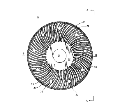
An electrodeposited diamond wheel 10 in this embodiment
is used for cutting a composite material 60 (see Figs. 8 and
9) made of a heat-softenable material 61 and a reinforcing
material 62. The heat softenable material 61 may be softened
by heat and includes all materials made of a heat-softenable
substance such as, thermoplastic elastomers, fibre reinforced
thermoplastics, GRTP(glass fibre reinforced thermoplastics),
CRTP (carbon fibre reinforced thermoplastics), natural rubbers
and thermoplastic resins.
The reinforcing material 62 may be any reinforcing
material such as steel materials, steel wires, carbon fibres,
glass fibres, minerals (including stone material)
and the like.
Examples of the composite material 60 include vehicles
tires, rubber conveyor belts or tracks, and high pressure
rubber hoses, as well as other composite materials 80 contai-
ning various kinds of reinforcing material 62.
The diamond wheel 10 in this embodiment comprises a
circular disc 20, with diamond abrasive particles 30 as the
main constituents, and a plating layer 40 for bonding the
diamond abrasive particles 30 to the circular substrate.20.
The circular substrate 20 in this embodiment is a metal plate
having a low heat expangion coefficient such as an Ni30-50% --
Fe alloy and, specifically, INVAR or Fe-36% alloy is used. As ~
shown in Fig. 1, the circular substrate 20 has an attachment
aperture 21 formed ~t a centre for attaching the diamond wheel
to a rotational device (not illustrated) that rotates the
diamond wheel 10. A plurality of cooling apertures 22 are
formed at a predetermined distance from the attachment
aperture 21 between it and the outer circumference at a
predetermined pitch. The substrate 20 typically has a
diameter of about 4" (10.16 cm).
7
2191796
Ridges 23 each having an arcuate cross-sectional shape,
and grooves 24 located between the ridges 23 form corrugations
on each side of the circular substrate 20. In this embodi-
ment, the ridges and the grooves are alternately formed on
each side surface of the circular substrate 20 and arranged in
a regular pattern, but the diamond wheel 10 may also be formed
such that the ridges 24 and the grooves 23 are irregular by
disposing ridges 23 of increased width (circumferential
direction) together.
The height of each ridge 23 is gradually increased toward
the outer circumference. Further, the width of the ridge 23
is decreased toward the centre of the substrate 20. The
beginning of each ridge 23 in this embodiment is formed near
the attachment aperture 21, as can be seen in Fig. 1. This
feature is different in the embodiment shown in Fig. 10, and
is described below.
The ridges 23 and the grooves 24 are preferably curved in
a vortex shape, which is formed radially in the direction
opposite to the direction of rotation of the diamond wheel 10.
Further, as shown in Fig. 2, a width W defined by an
outer surface of a ridge 23 on one side and an outer surface
of a ridge 23 on the opposite side of a corrugation situated
at the outer circumference of the substrate 20 is the widest
part of the substrate 20.
Diamond abrasive particles 30 are electrodeposited on the
outer circumference of the circular substrate 20. That is, the
ridges and grooves are formed as corrugations on both sides of
the circular substrate 20, and the diamond abrasive particles
30 are electrodeposited on the outer circumference of the
corrugations to form a cutting edge, the cutting edge being
corrugated in a shape conforming to the substrate 20.
Since the diamond abrasive particles 30 are electro-
deposited (using an electric plating method), they are bonded
as one layer to the substrate 20 by a plating layer 40. The
size of the diamond abrasive particles is suitably within a
range of from 30 to 80 mesh and, preferably, within a range of
from 40 to 80 mesh.
8
211196
Referring to the particle size, there are two factors
that must be considered in cutting the composite material 60.
One is heat generation in the heat-softenable material 61
induced by friction and the other is the necessity for cutting
a hard material since the composite includes the reinforcing
material 62. Accordingly, while smaller diamond abrasive
particles 30 are preferred for cutting the reinforcing
material 62, a small particle size results in a disadvantage
because the particles are easily coated by the heat-softenable
material 62 as friction increases and the diamond wheel 10
loses its cutting performance. The above mentioned particle
size range has been found to be preferred in view of the
results of experiments.
Further, since the electrodeposition method is adopted
as a means for securing the diamond abrasive particles to
the substrate 20 to make the diamond abrasive particles 30
the cutting edge, all the diamond abrasive particles 30
should protrude from the plating layer 40 by a predetermined
amount so they can serve as the cutting edge for the composite
material 60. As shown in Fig. 7, the amount of protrusion is
represented as "Y-X = amount of protrusion." By optimizing
the amount of protrusion, the portion in contact with the work
to be cut (composite material 60) is minimized and heat
generation is correspondingly reduced during grinding
(cutting) .
While the amount that the diamond abrasive particles 30
are embedded in the plating layer 40 is represented by a ratio
expressed as X/Y x 100, (hereinafter referred to as the
"embedding ratio") as shown in Fig. 7, and the embedding ratio
is preferably in the range of 60% - 80%. If the embedding
ratio is less than 60a, although the cutting performance is
satisfactory, the diamond abrasive particles 30 tend to be
torn off during cutting after a slight increase in the
exertion force (the resistive force during cutting increases
as the diamond cutting edge is abraded by use). This loss of
abrasive is more pronounced as the embedding ratio is
decreased. Accordingly, an embedding ratio of less than 60a
9
2~~yC~~
shortens the working life of the diamond wheel 10, which is
undesirable.
On the other hand, if the embedding ratio exceeds 80%,
the amount of the diamond abrasive particle 30 protruding
above the plating layer 40 is reduced, causing contact between
the work to be cut (composite material 60) and the plating
layer 40, and interfering with the discharge of cutting dust
during cutting. This results in heat generation which makes
cutting impossible. Heat generation increases as the
embedding ratio is increased above 800, which is not
appropriate.
When the composite material 80 made of the heat-
softenable material 61 and the reinforcing material 62 is cut,
the reinforcing material 62 is easily cut by the diamond
abrasive particle layer of a prior art diamond wheel. However,
in cutting the heat-softenable material 61, heat was generated
by friction between the diamond wheel and the heat-softenable
material 61 due to the high rotation speed of the diamond
wheel. Consequently, the heat softened or melted the heat-
softenable material 61 and the material was deposited on the
diamond abrasive particles and eventually coated the entire
surface of the diamond abrasive particles. Thus, the diamond
abrasive particles lost their ability to cut or grind, which
further increased the heat generated by friction and made
further cutting impossible.
However, as shown in Fig. 8 and Fig. 9, when cutting with
the diamond wheel 10 in accordance with the invention, the
diamond abrasive particles 30 and the composite material 60
are in contact only at the ridges 23 of the corrugations at
which grinding (cutting) occurs. In addition, because the
substrate is composed of a metal having a low heat expansion
coefficient, thermal deformation of the diamond wheel 10 is
minimized and contact with the work to be cut is also
minimized during use. Furthermore, grooves 24 function as
passages for the flow of cooling air which convects away heat
generated between the diamond wheel 10 and the composite
material 60 and, at the same time, the grooves 24 provide a
21 ~77C)6
passage for discharging cutting dust thereby further promoting
smooth cutting.
In the embodiment shown in Figs. 10 to 14, the basic
construction is the same as that in the previous embodiment,
but the corrugations start at a position that is about one-
half of the radius of the substrate 20. In addition, the
number of ridges 23 and the grooves 24 forming the
corrugations is increased. As well, more of the cooling
apertures 22 are provided. In this embodiment, the substrate
20 typically has a 12 inch (30.4 cm) diameter. Otherwise,
diamond wheel 10 is constructed the same as described above
for the first preferred embodiment.
11