Note: Descriptions are shown in the official language in which they were submitted.
CA 02197920 2005-04--04
S P E C I F I C A T I 0 N:
The present invention relates to a vertica]. axis wind mill having
variable pitch flat blades and booster curtains attached to the ends of
radial arms. Present practice for wind energy converters is to use
horizontal axis propeller type wind turbines with the generator at the
same difficult to service elevation as the propeller. These wind turbines
have a relatively low efficiency and are self-starting at wind speeds of
only 15 to 20 km/hr. some only at 30 km/hr or even higher wind speed.
The present invention makes the most of the fact that work is the product
of force time lever arm. Wind blowing on a large flat area that is
attached to a vertical shaft exerts a substantial torque on the shaft.
This principle is applied in the present invention by using variable
pitch flat blades and booster curtains attached to the ends of structural
arms that extend radially from a vertical s:haft and rigidly connected
thereto thus creating a torque on the vertical shaft. The vertical shaft
is guyed to the ground using a slip collar and guy wires for lateral
stability and it has at the bottom a large :sprocket wheel rigidly
attached to it which transfers the torque to a small sprocket wheel of a
generator. The generator is thus easily accessible at or below ground
level. A considerable advantage over convent:ional wind turbines, Also,
most parts of such relatively simple wind mill can be made by steel
fabricators anywhere.
- 1 -
CA 02197920 2005-04-04
The arrangement presented four problems which had to be solved in an
inventive way. They are:
a) The manner in which the structure is stabilized,
b) how, when, where and at what rate the pitch of the flat blades is
to be changed to attain best efficiency,
c) the use of booster curtains,
d) how, when and where the booster curtains are to be lowered and
raised.
Having thus generally described the nature of the invention, reference is
made to the accompanying drawings showing by way of an example specific
embodiments thereof and in which :
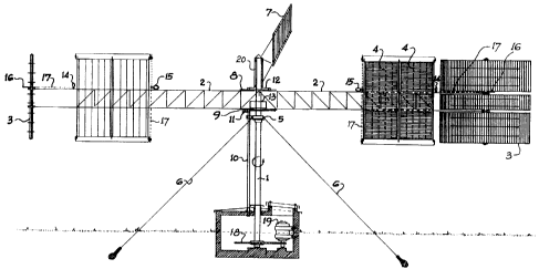
Figure 1 is an elevation of the vertical axis wind mill with a right
hand arm at the 0 position and the opposite arm at the 180
degree position of a circle in a plan view as shown in dotted
lines in Figure 2.
Figure 2 is a plan view showing in diagrammatic way the radial arms, the
weather vane, the motor control switches for blade pitch and
curtain control, the motor speed and direction control device,
the direction of the wind and the pitch of the flat blades
to be attained at various positions of the radial arms.
The following reference characters are used :
1 vertical shaft 6 guy wire
2 radial arm 7 weather vane
3 variable pitch, three 8 top circular steel plate
section, flat blade with motor control switches
4 booster curtain 9 bottom circular steel plate
slip collar with power pick-up rings
- 2 -
CA 02197920 2005-04-04
external power supply 22 switch actuator for pitch con-
conduit trol motors on arms at the
11 power pick-up rings 135 and 315 degree positions
12 circular cover plate with 23 switch actuator for pitch con-
switch actuators, a rim and trol motors on arms at the
perimeter seal 45 and 225 degree positions
13 motor control box 24 directional on-off switch
14 variable speed, bi-directional for curtain control motor
electric motor, moving pitch 25 directional on-off switch actu-
of blades ator for curtain control motor
bi-directional electric motor at position 270
raising or lowering booster 26 directional on-off switch actu-
curtains ator for curtain control motor
16 sprocket wheel or sheave at position 90
17 drive chain or belt 27 speed and direction control de-
18 large diameter sprocket wheel vice for pitch control motorsl4
19 generator 28 direction of wind
sleeve over vertical shaft 29 windward side
21 alternate on-off switch for 30 leeward side
pitch control motors 31 small diameter wheel
0,45,90,135, are positions of radial arms in degrees on a circle
180,225,270, in plan view, where 0 is at the right hand side.
315 and 360
Figure 1 is to a large degree self explanatory to a structural or
mechanical engineer. Variable pitch flat blades 3 need to be in three
sections in order to use the area between the top and bottom chords
- 3 -
CA 02197920 2005-04-04
of the truss-, like 'radial arms 2. The three sections of blades 3 are
rigidly attached to a vertical axis which is rotated by sprocket wheel or
sheave 16 that is moved by a chain or belt 17 driven by motor 14. Booster
curtains 4 are shown to be of the pull down type, rolled around a hori-
zontal shaft at the top of a structural frame when open. Motor 15 will do
both, raise or lower the curtains. The top and bottom chords of truss-
like radial arms 2 are connected to vertically spaced apart top and
bottom circular steel plates 8 and 9 respectively and these horizontal
plates are rigidly attached to vertical shaft 1, thus transferring
torque, vertical and lateral loads thereto. Lateral stability of the
structure is attained by the solid attachment to vertical shaft 1 of a
circular angle just below bottom steel plate 9, the placement of a slip
collar 5 on top of the circular angle and the connection of four guy
wires 6 at 90 degrees to the slip collar 5 and anchored to the ground.
Slip collar 5 does not rotate.
A pipe-like sleeve 20 is placed over an extension on top of
vertical shaft 1. On the side of that sleeve 20 is rigidly connected
weather vane 7 and at the bottom a circular cover plate 12 with a rim and
a perimeter seal to keep out rain, wind and ice from motor control
switches that are located between cover plate 12 and top circular steel
plate 8. Motors 14 and 15 need electric power which is supplied from
generator 19 or a power grid via stationary conduit 10to power pick-up
rings 11 on the underside of the normally rotating bottom circular steel
plate 9. At the bottom of vertical shaft 1 is attached a large diameter
sprocket wheel 18 that drives a small diameter sprocket wheel of
generator 19.
- 4 -
CA 02197920 2005-04-04
The example shown in diagrammatic fashion in Figure 2 shows a wind mill
with four radial arms 2 extending cross-like from the vertical shaft 1
but rotated by 45 degrees. In dotted lines is the preceding position when
two arms were in the 0 to 180 degree direction to illustrate the pitch of
flat blades 3 in the corresponding positions of the four arms. In the
shown example the wind blows in the direction 28 i.e. from the bottom of
the page to the top of the page, thus holding weather vane 7 on the
leeward side 30 of vertical shaft 1 i.e. the 90 degree position and
rotates the wind mill counterclockwise. This counterclockwise rotation of
the wind mill is achieved by the force of the wind acting on flat blades
3 that are turned to such a pitch with respect to the radial arms 2 and
by the booster curtains 4 so as to attain maximum counterclockwise torque
substantially on the right hand side of the wind mill and near minimum
resistance from the blades and the curtains when returning against the
wind, substantially on the left hand side of the wind mill.
In the example shown in Figure 2 the four radial arms are in a 45
degree diagonal position thus obtaining four 90 degree sections, one at
the top in which weather vane 7 is exactly in the middle, one at the
bottom, one at the right and one at the left side of a circle. These
sections remain always aligned with weather vane 7 and are significant
for the pitch control of flat blades 3 as follows. in the top and bottom
90 degree sections the pitch of flat blades 3 will not change. In other
words, the 45 degree right slash pitch of flat blade 3 on radial arm 2 at
the 45 degree position does not change until radial arm 2 reaches the 135
degree position. And in the bottom 90 degree section the 45 degree
- 5 -
CA 02197920 2005-04-04
left slash pitch'of flat blade 3 on radial arm 2 does not change until
this radial arm 2 reaches the 315 degree position. In both, the left and
right 90 degree sections the flat blades 3 will rotate clockwise by 90
degrees. In other words, when a radial arm reaches position 135 or
position 315, the flat blades 3 will begin to rotate clockwise at a rate
that by the time radial arms 2 reach position 45 or 225 flat blades 3
will have rotated clockwise by 90 degrees and the stop.
Booster curtain 4 on arm 2 that reache4s a position opposite
weather vane 7 i.e. the 270 degree position, will be lowered i.e. closed.
When the opposite arm 2 reaches the position under weather vane 7 i.e.
the 90 degree position, booster curtain 4 on that arm will be raised i.e.
opened. All the movements of flat blades 3 and booster curtains 4 are
accomplished by electric motors 14 and 15 which are controlled by weather
vane 7 in such a way that the relative positions of blades 3 and curtains
4 with regard to the weather vane 7 are always attained, no matter from
what direction the wind is blowing.
At the bottom of sleeve 20 is attached a circular cover plate 12,
the bottom of which is about one inch from the top of top circular steel
plate 8. In this space of about one inch between these two horizontal
plates are located eight switches, four switch actuators and a motor
speed and direction control device. All positions mentioned hereafter are
on a circle of 360 degrees and are relative to the position of weather
vane 7 which is always at position 90 i.e. on the leeward side of
vertical shaft 1. On top of top circular steel plate 8 are mounted four
alternate on-off switches 21, one each on diagonals in the 45, 135, 225
and 315 degree position on a radius so as not to interfere with speed and
- 6 -
CA 02197920 2005-04-04
direction control*device 27. Also on top of top circular steel plate 8
are mounted four directional on-off switches 24, one each on the same
diagonal positions as switches 21 but on a smaller radius so as not to
interfere with switch actuators 22 and 23. In addition, on top of top
circular steel plate 8 is mounted the axis of speed and direction control
device 27 near the rim of circular cover plate 12 at the 270 degree
position. Mounted to the underside of circular cover plate 12 are four
switch actuators. Switch actuator 22 is attached at the diagonal 315
degree position on a radius so as to switch on alternate on-off switches
21 when they pass by. Switch actuator 23 is mounted at the 45 degree
diagonal position on the same radius as switch actuator 22 so as to
switch off alternate on-off switches 21 when they pass by when top
circular steel plate 8 rotates. Directional on-off switch actuators 25
and 26 are mounted on the underside of circular cover plate 12 at the 270
and 90 degree positions respectively at a radius so as to switch on or
off directional on-off switches 24 for curtain control motors. On the
outside rim of circular cover plate 12 will be attached a seal so as to
keep out rain, snow and ice. The seal will be in contact with top
circular steel plate 8 producing some friction thus requiring a certain
force to rotate cover plate 12. However, weather vane 7 will be of a size
and have an arm of a length so that it will overcome the inertia at a
wind speed of about 3 km/hr. All power to all electric motors will be
switched off when the wheel of speed and direction control device 27
stops, i.e. when the wind mill as well as the weather vane 7 stop
turning.
- 7 -
CA 02197920 2005-04-04
In the diagram as'shown in Figure 2 the wind blows in direction 28 or
from position 270 to position 90 or from the bottom to the top of the
page thus keeping weather vane 7 steady on the leeward 30 side of
vertical shaft 1 and turning the wind mill and with it top circular steel
plate 8 in a counterclockwise direction. When one radial arm 2 reaches
position 315 and the opposing arm position 135 switch actuator 22 will
trigger switch 21 to start two motors 14 so as to begin to rotate blade 3
on the extremity of each of these two arms in a clockwise direction. At
the same time the other two radial arms 2 of a four arm wind mill will
reach positions 45 and 225 when switch actuator 23 will trigger alternate
on-off switch 21 to stop motors 14 and with them the rotation of blades 3
on these two arms 2. Since blade 3 at the end of arm 2 in position 315 is
on a 45 degree backslash pitch with respect to arm 2 and blade 3 of arm 2
in position 45 is in a 45 degree forward slash pitch the clockwise
rotation of blades 3 is by exactly 90 degrees between these two positions
of arm 2. This is also the case for blade 3 on the opposite arm 2 between
positions 135 and 225.
Since the perimeter speed of the wind mill under heavy wind
conditions will be higher and therefore the time to rotate radial arms 2
by 90 degrees will be reduced while the clockwise rotation of blades 3
will still be by the required 90 degrees in a shorter time, it is
necessary that motors 14 have controllable speed. Such control is coming
from speed and direction control device 27, which operates in the
following manner. The location of device 27 has been specified
earlier. Device 27 consists of a small diameter shaft attached to the
top of top circular steel plate 8 at such a position that a small
- 8 -
CA 02197920 2005-04-04
diameter whe(;l 31'touches the rim of circular cover plate 12. Under
normal operation the wind mill and top circular steel plate 8 turn in
counterclockwise direction at a certain speed and weather vane 7 with
circular cover plate 12 are stationary. This will turn the small wheel 31
of speed and direction control device 27 in a clockwise direction at a
speed in a certain ratio to the perimeter speed of the wind mill. Device
27 can therefore send via motor control box 13 two signals to motors 14
i.e. in what direction to turn and at what speed.
In the case when the direction of the wind shifts so as to turn weather
vane 7 in a clockwise direction it will have the effect of turning the
small wheel 31 of speed and direction control device 27 faster in the
same direction and device 27 will therefore send the signal to turn
faster to the two motors 14 that are changing the pitch of blades 3.
In the case when the direction of the wind shifts so as to turn
weather vane 7 in a counterclockwise direction it can have three
different effects, depending on the speed at which weather vane 7 is
rotated counterclockwise :
a) When weather vane 7 rotates counterclockwise at less than the speed
of the wind mill, which also rotates counterclockwise. In this case
the small wheel 31 of speed and direction control device 27 will slow
down, thus sending the signal to do the same to the two motors 14
that are on at that time.
b) When weather vane 7 rotates counterclockwise at the same speed as the
wind mill, which also rotates counterclockwise. In this case the
small wheel 31 of device 27 stops rotating, thus sending the signal
to the two operating motors 14 to stop.
- 9 -
CA 02197920 2005-04-04
c) In the rare case when weather vane 7 rotates counterclockwise at
greater speed than the wind mill, which also rotates counter-
clockwise. In this case all pitch and booster curtain controls will
work in reverse as switches will be triggered in reverse and the
small wheel 31 of device 27 will rotate counterclockwise, thus
sending the signal to the two motors 14 that are operating to rotate
blades 3 counterclockwise at the specific speed that depends on the
speed of the counterclockwise rotation of small wheel 31.
- 10 -